All Activity
- Past hour
-
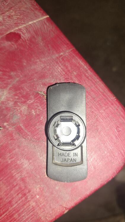
 I think that might be a YEC brand rotor. OE ones are Hitachi, they have a different logo.
 -

- Today
-
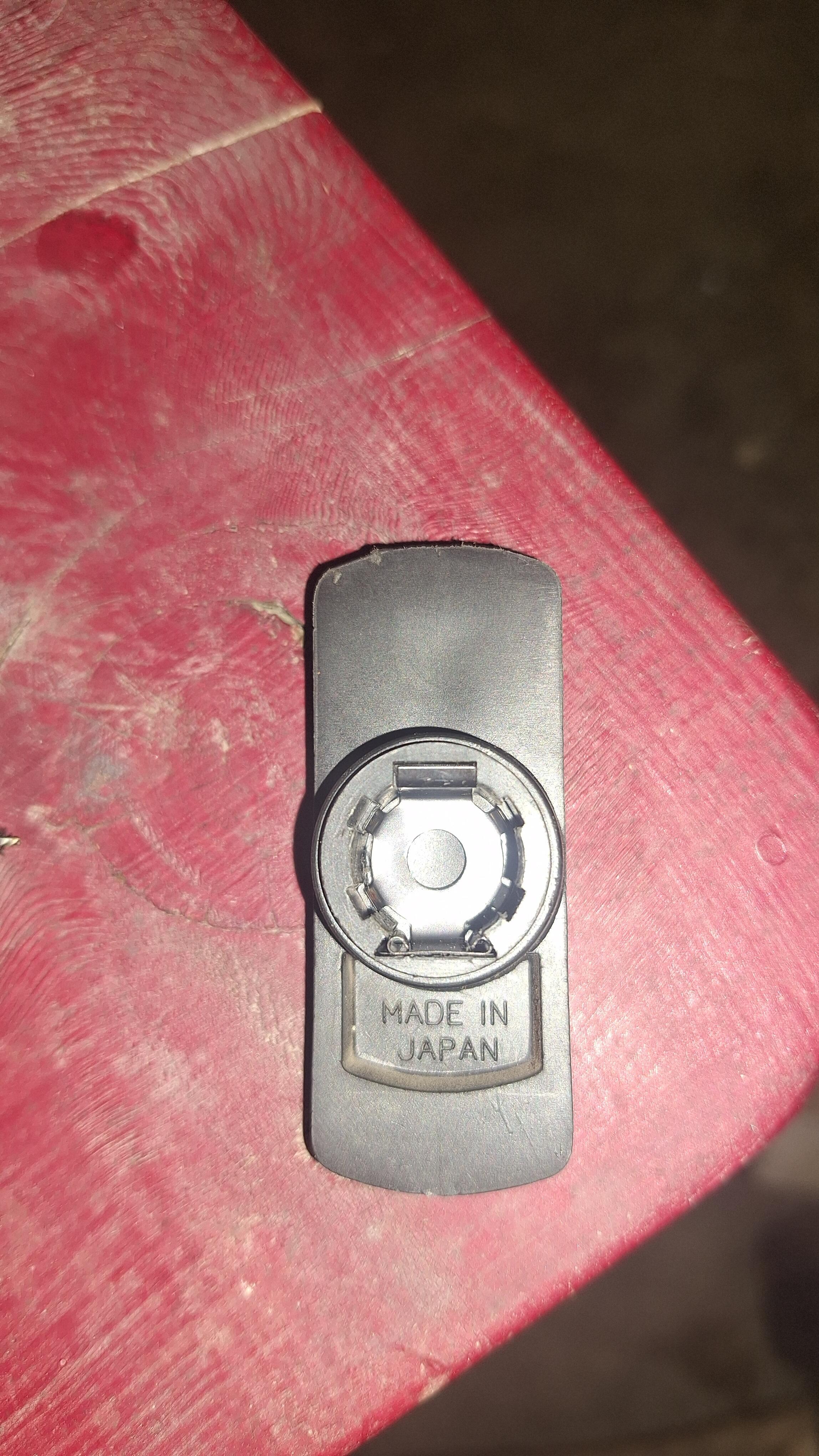
 Can anyone identify the logo or symbol on this rotor? It's of high quality and I would like to find another one. Could it be Mitsubishi?
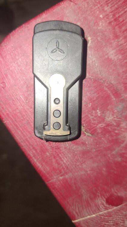
-
 Klocko98 joined the community
 -
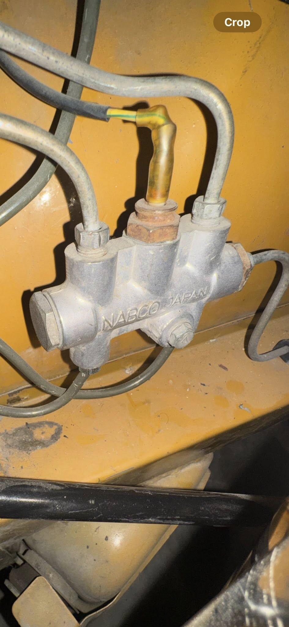
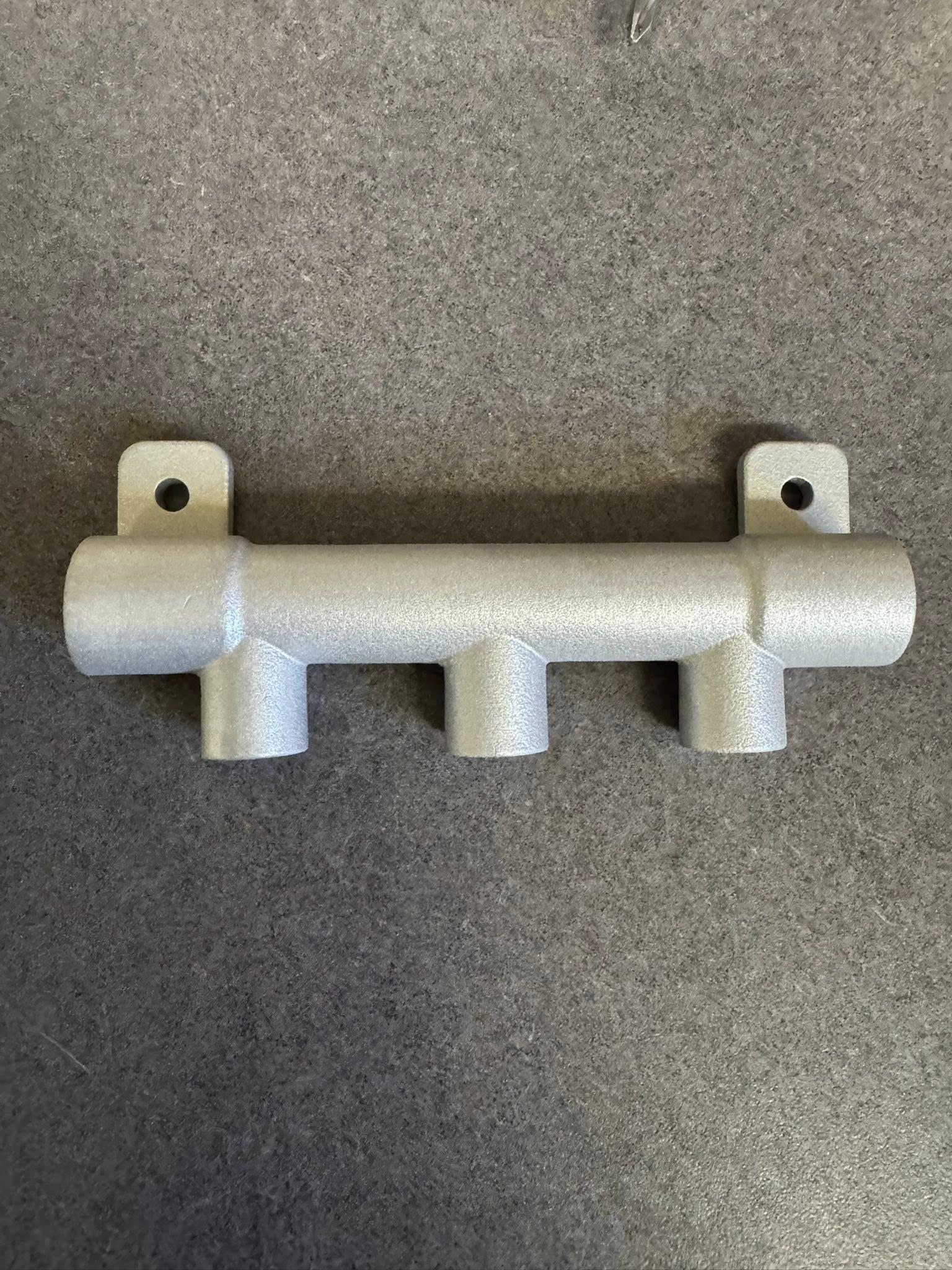
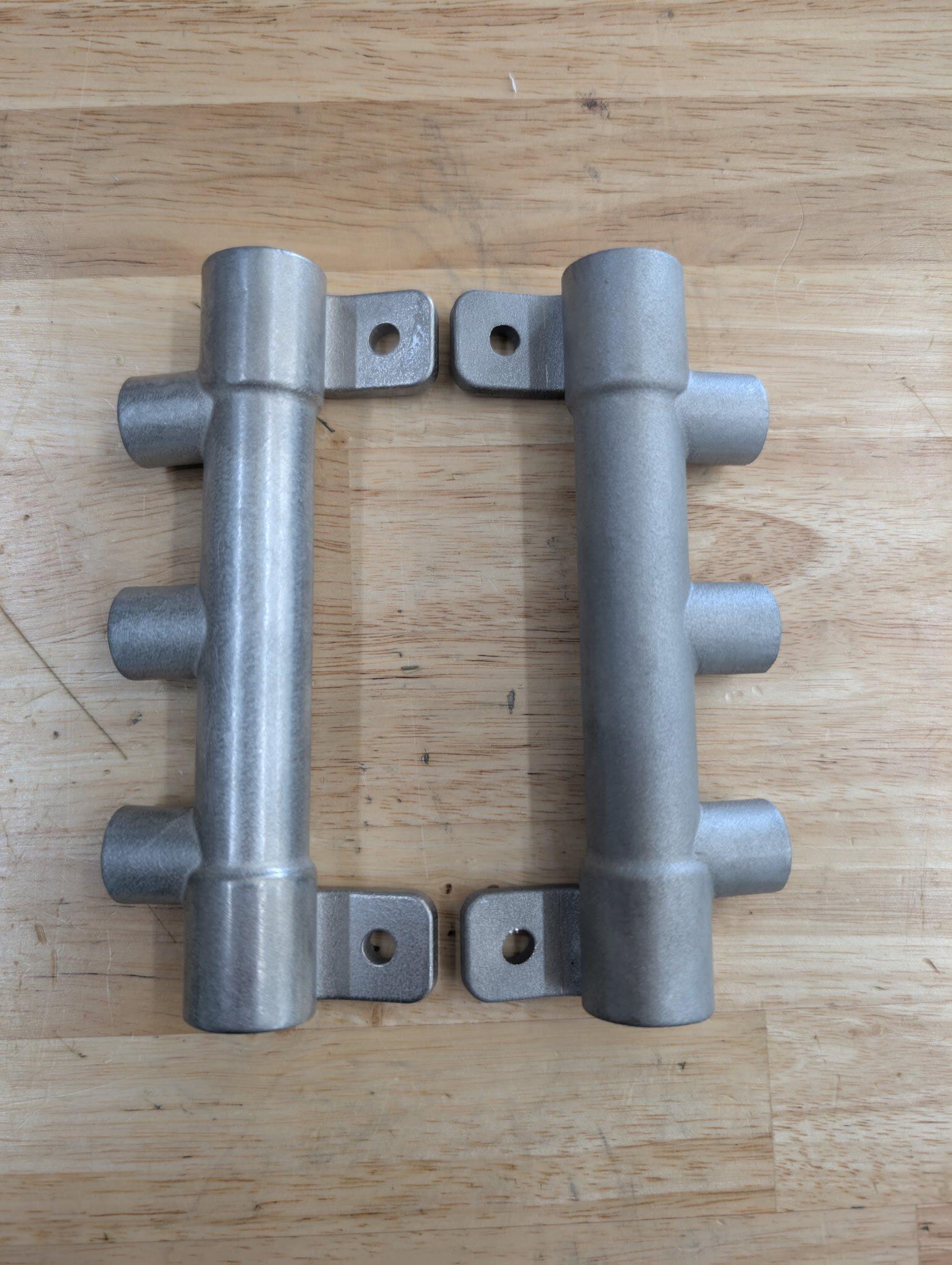
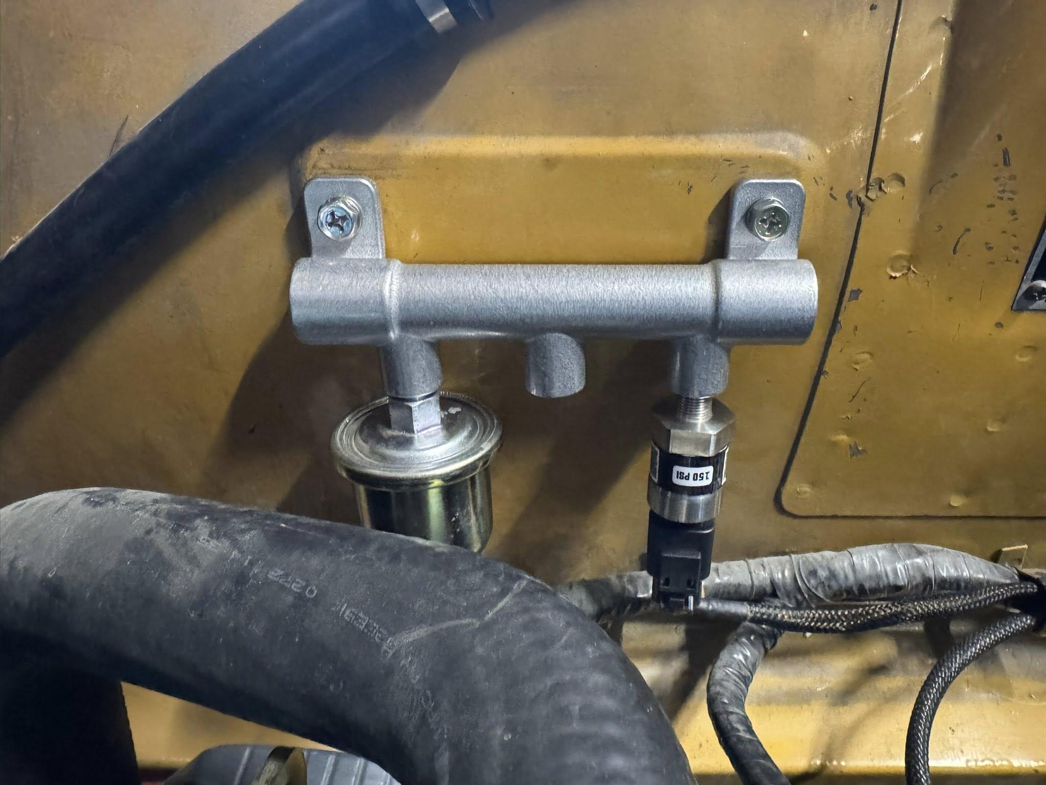
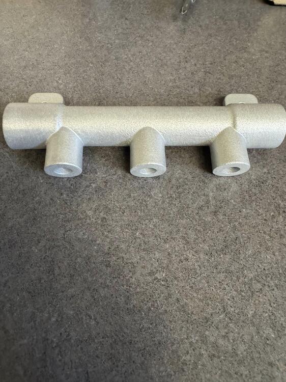
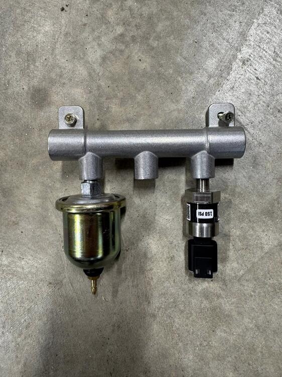
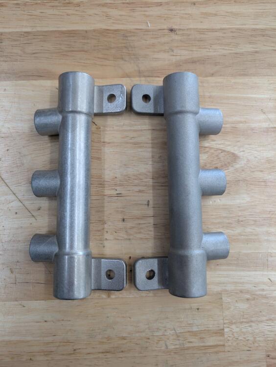
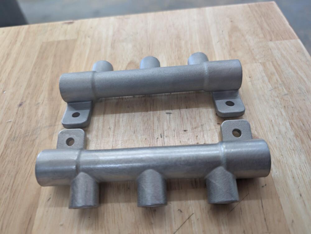
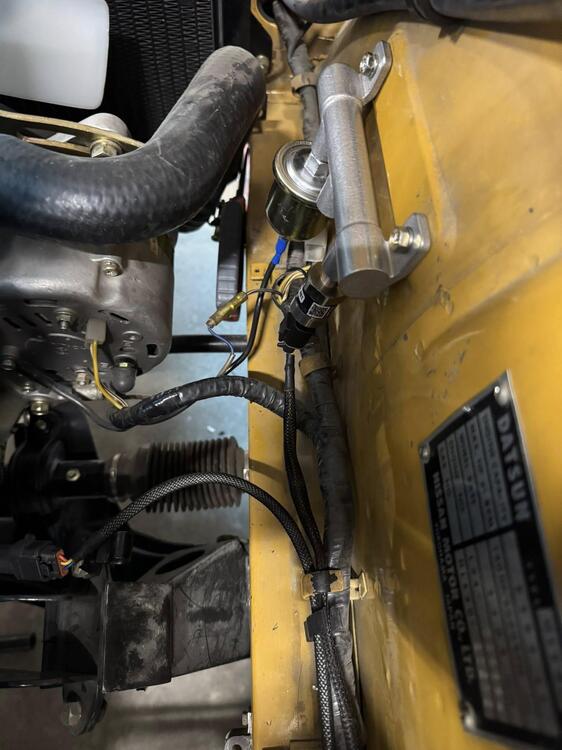
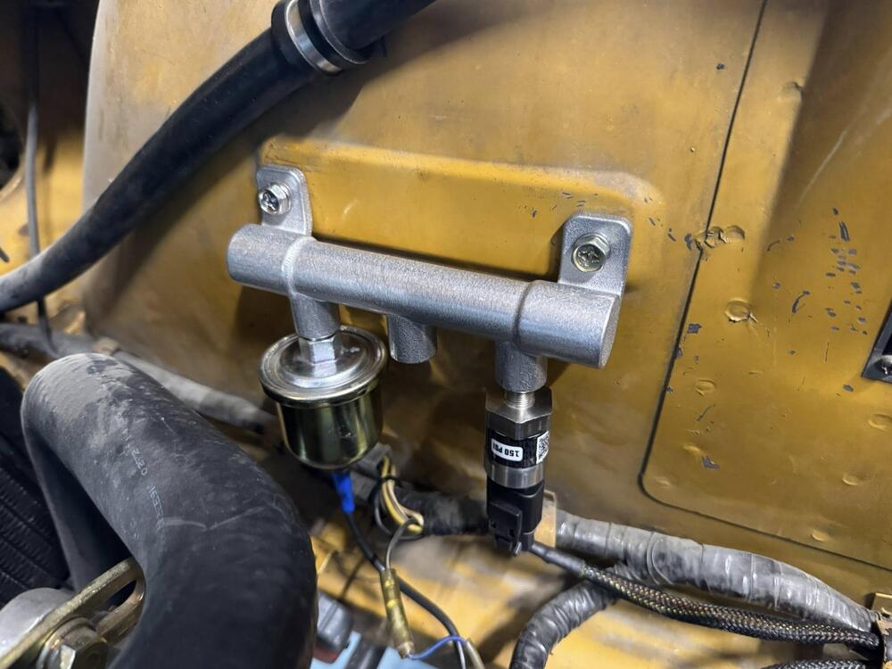
 Here is something fun/ silly I have been thinking of and finally made. It’s a remote oil pressure distribution block made to look like the stock 240z brake prop valve. I previously had a steel T In the block, that broke off and then when I was using an easy out I cracked my stock block bung. I said never again! 3D metal printing is neat stuff. I had it tumbled to look even more cast. I run stock gauges and my ecu needs its own signal. This location allows stock wiring to also work.


-
 This makes sense. This is likely the reason the previous owner had riveted it in place so that it wouldn’t accidentally lock as there isn’t a key hole nor rod knob.
 -
 It's been a while since I posted an update on the restoration! I have been driving the car - I have 488 miles on it. I reset both front and rear floats using the method in the factory workshop manual. To do so, I cut some "3d" finishing nails to the approximate lengths of 14 mm and 15 mm and then finished them to size with a benchtop grinder. The procedure from the factory workshop manual: Holding the assembly in its installed orientation (not upside down), I first place the 15 mm nail section in between the flat metal part of the float and the underside of the float chamber cover. I put it in place using needle nose pliers so that it is straight vertically. I pinch it to hold it in place by lightly squeezing the float and the chamber cover together. Note that when held in the installed orientation, the needle in the needle is in "free fall" and is in a fully open position. Then, using a magnifying glass, I inspect the area of the float tab and the tip of the needle. I verify that the tip of the needle is not touching the curved arm (tab) of the float. It does have to be within 1 mm of it however. If not, when you swap to the 14 mm nail section, the tab will still not touch the tip of the needle. I adjust the tabs so that both carburetor floats contact the tip of the needles with the 14 mm section of the nail in place. Interestingly, after I had set the floats this way, I noticed that with the 15 mm section of the nail in place, I could blow through the fuel inlet tube, and with the 14 mm section of the nail in place, I could not. So, what I found was that from fully open, to seated, the needles have less vertical movement than 1 mm. While I have been driving the car to break the engine in, I have been looking at air fuel ratios (AFR) using a wideband 02 sensor. I swapped from what I believe to be stock N27 needles to some SM needles. But, I have observed AFRs moving around a bit which is unusual and not expected, and which I think may be due to the engine still breaking in. I started a separate thread that details more about what I was doing and seeing here: https://www.classiczcars.com/forums/topic/69292-choosing-an-su-needle-if-i-have-needle-station-info-and-real-world-afr-can-i-use-that-to-find-the-right-needle/ This weekend I plan to do a leak down test on the engine to confirm break in is complete, change to standard oil (instead of break in oil), and adjust the valves. If the engine is fully broken in, I will do some more AFR testing and determine how to proceed. I may need to modify the SM needles in the cruising and pick up stages by some very light "sanding" - removing material by chucking them up in drill and using 2500 grit sandpaper only in a certain area of each needle. With the driving I have done, I also noticed a vibration at higher speeds. I started a separate thread for that issue: https://www.classiczcars.com/forums/topic/69334-how-vibration-free-is-your-70-71-240z/#comment-675670 Today, I am going to buy a digital angle gauge so I can check some angles in the driveline. I am hopeful doing this will help me determine the cause and fix that issue.
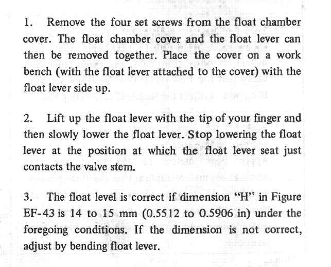
-
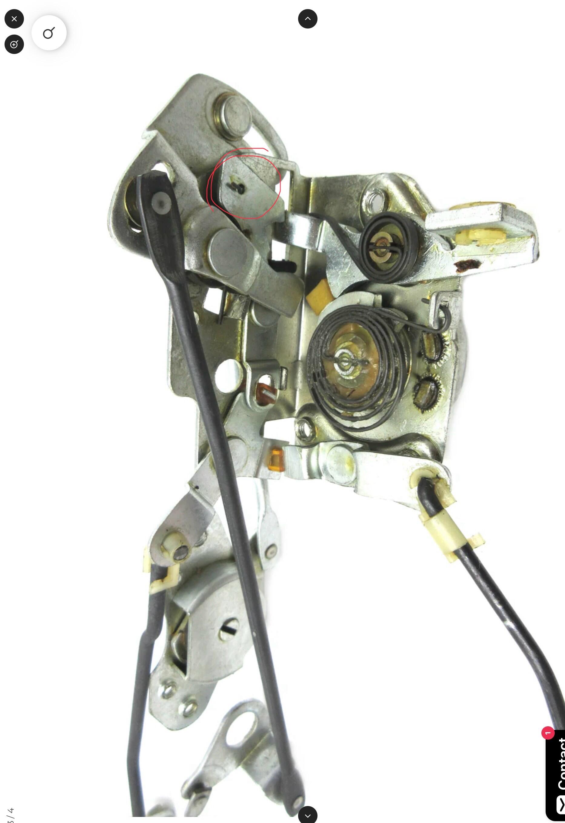
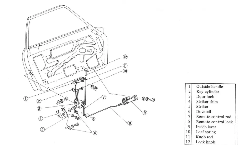
So in the last pic, the part with rivet, lets call it the "hook". It is touching a bar just to the right. We'll call it the "drum catch". When the drum in the center w the spring rotates the "drum catch" locks into the ratchets on the drum. When it does that the "drum catch" moves down slightly. Then the "hook", which is the lock mechanism, can move over to prevent the "drum catch" from unlatching. I would make you some pictures but all my locks are at the platers. I just recently studied this mechanism as I went through mine and was working on refurbishment
-
sigh, i think i know what’s going on. the previous owner put a rivet on the lever here so it wouldn’t move. when it should look like this instead:


- Yesterday
-
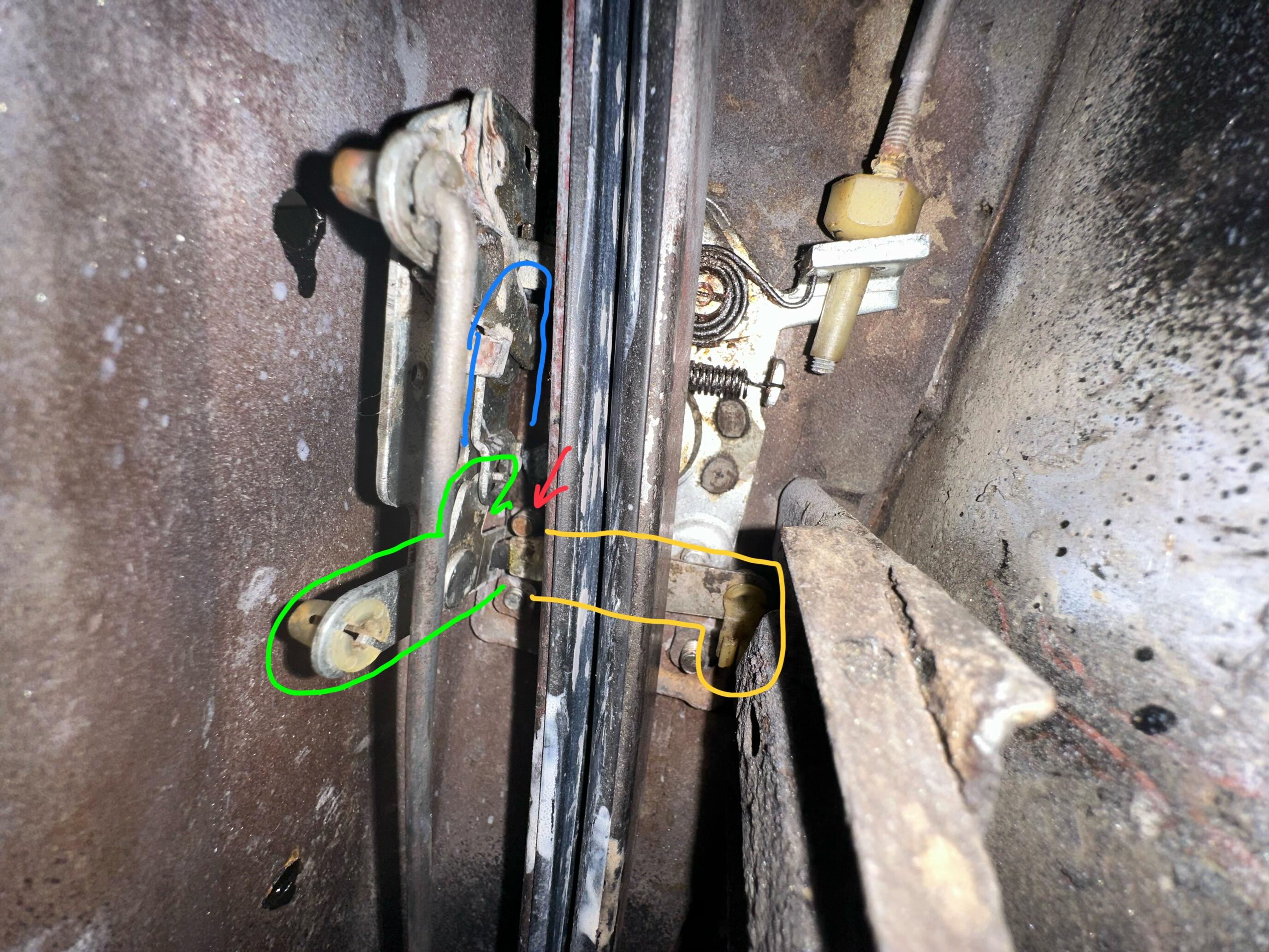
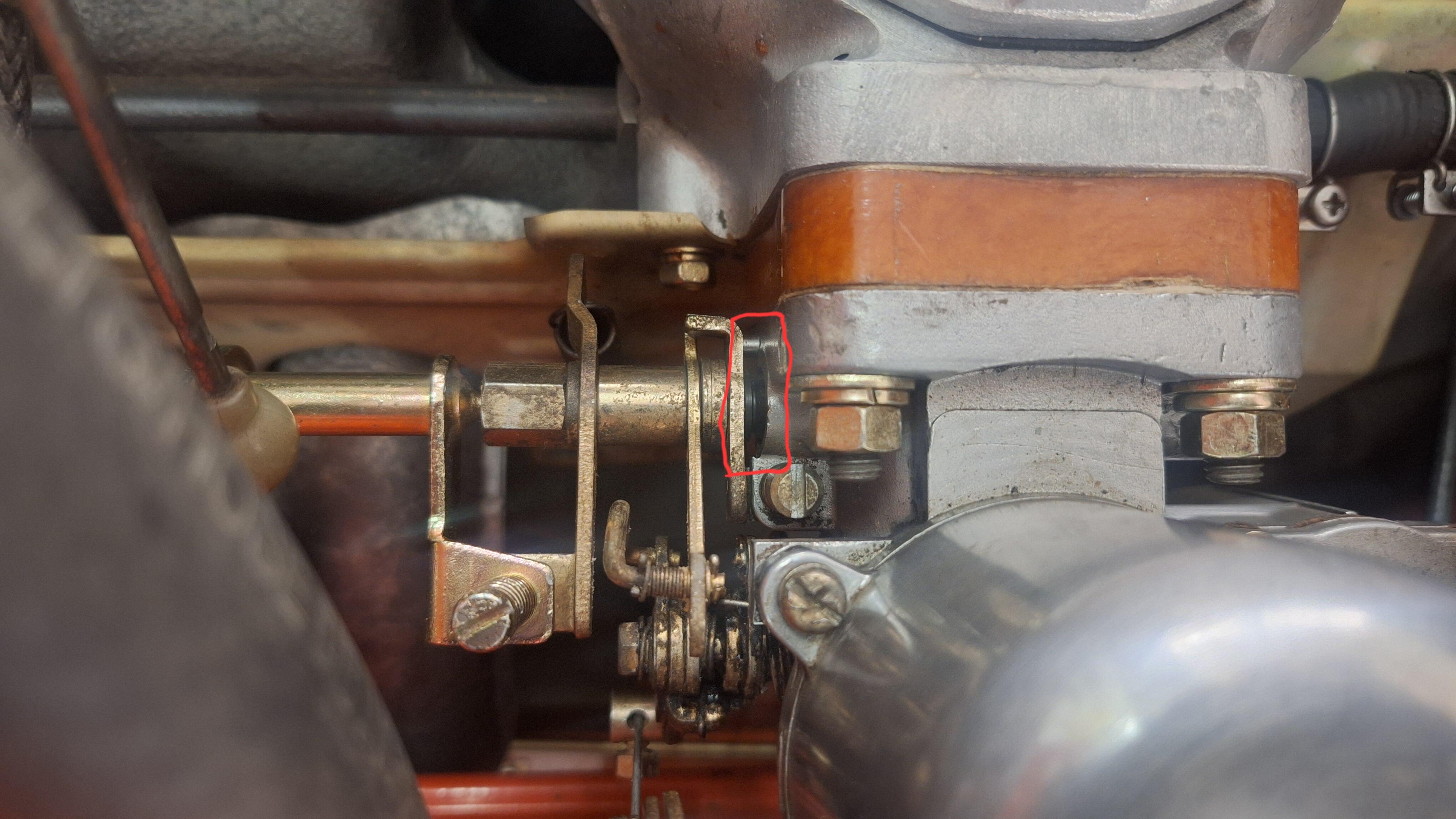
So before I go and dismantle the window/door etc, I have a question about how this is supposed to work. As it sits now, the door latches and opens fine. You can see the red arrow pointing at the mounting screw. This looks like it prevents the knob rod (green) and the keyhole tab (yellow) from moving downward. Is this expected? If the knob rod (green) was working as intended, would the blue part move as well? With the green/yellow parts in that position, are they in a door locked or door unlocked position? May be an obvious answer, but I thought I would ask to be 100% sure. I’m wondering if the previous owner did something crazy like weld it to keep it “unlocked” forever. Thanks in advance!

-
 Take lots of pics for reference.
 -
I haven’t done that yet. I was going to try what I could before going down that rabbit hole. Looks like I may have to?
-
Have you removed the entire mechanism and performed a deep clean along with lubricants?
-
I rotated the latch so it’s facing directly south. I tried with all my might to lock downwards, but it would just not move. I haven’t yet fabbed something but I did also try a wrench to push down and it would just not budge. I wonder what I’m missing here. Video for reference: IMG_7463.mov
-
 I had forgotten about that. Reminded me that you have to lock the door with the key from the outside after you close it, if you want to lock it and leave it. Of course, based on the above. The knob is only for locking yourself in. I used the knob to work the mechanism free becuase I was afraid that I would break the key.
 -
This is also super helpful. I will report back when I get some time to lock/force that lever. Thank you!
-
The doors will not lock unless the door latch is latched. In other words they won't lock unless the door is shut or you manually rotate the door latch to the locked position
-
This is super helpful. I’ll give that a shot! Thank you! It is currently unlocked so I would guess I could fab something and press down hard.
-
I remember the lock mechanism on my 76 being almost impossible to move even with the knob and cylinder attached correctly. It might be that you just need to get a better grip on the part that the knob rod attaches to and pull harder. Might be worthwhile to fabricate a new rod and attach it to give you something to pull and push on. With lubrication and some manual working the mechanism on mine eventually loosened up. The car had sat for many years before I got it.
-
I purchased a 240z that had the knob rod and key cylinders deleted. I thought I could put in an actuator to trigger the “lock”, but I think I’m missing something or maybe the key cylinders is a required part of the lock working? To be clear, there’s no vertical knob rod ie no #11, #2 per the diagram. When I reach inside the door to wiggle what I think the knob rod is connected to, it just moves up and down a little bit and as far as I can tell, there’s no way to lock the door that way either. Any help would be appreciated! Please let me know if I can provide more information. Thank you!
-
 goneforgood joined the community
 -
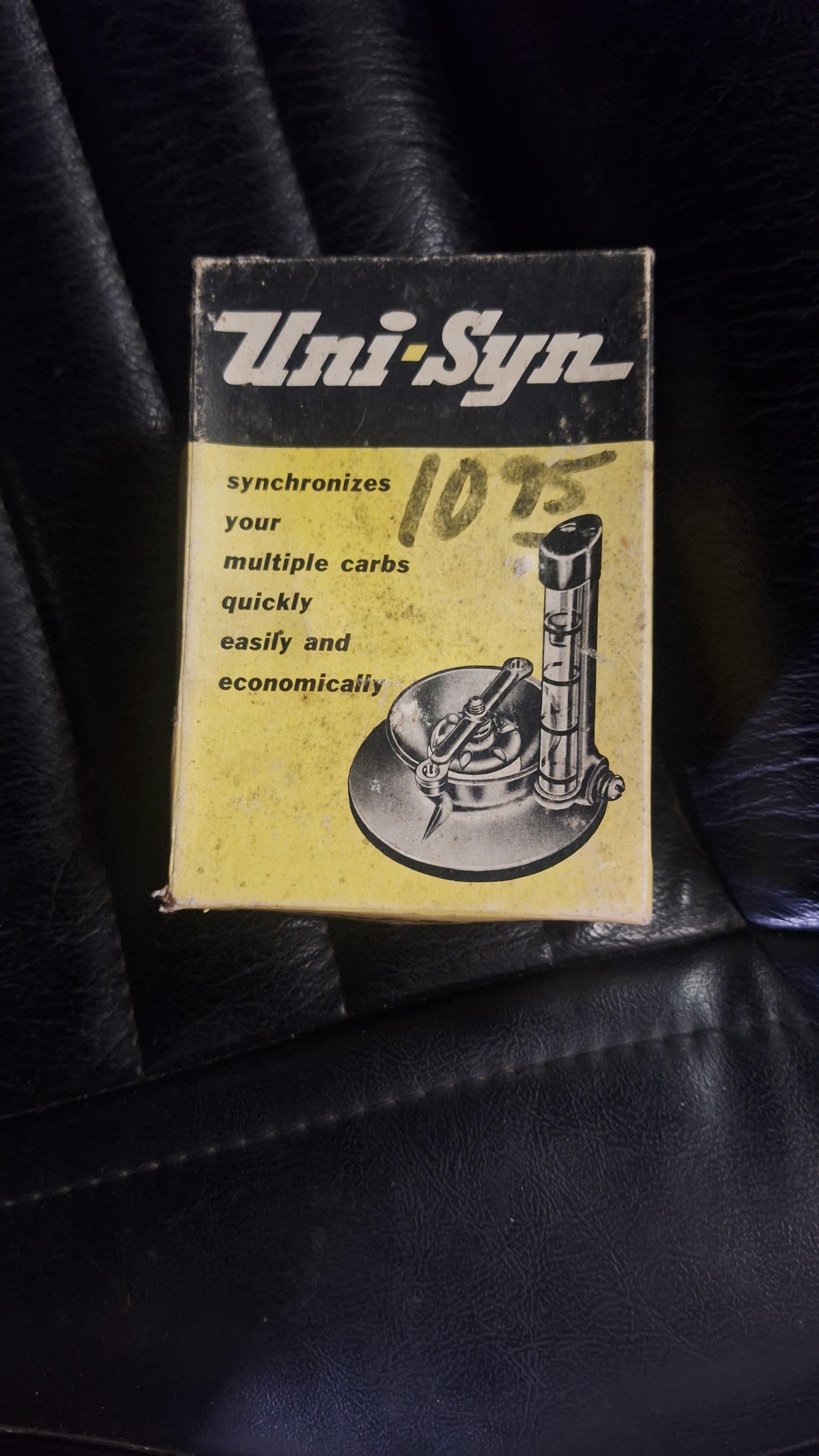
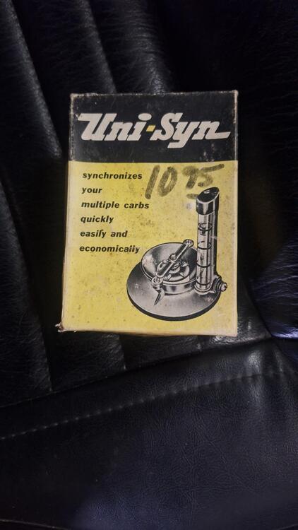
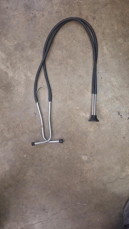
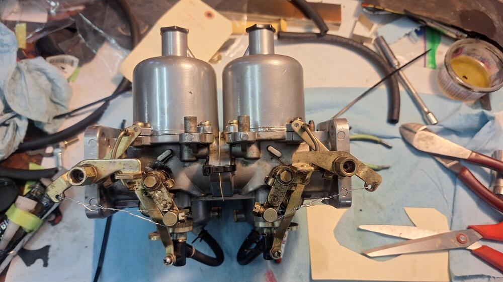
After adjusting the valve lash a couple times, I timed the distributor which was really close. I tried my hand at tuning the carbs. This video VHS and flowmeter came with the car. I backed everything off, but still was getting a 1,000 rpm idle. Seemed a bit high. I would put the flow gauge on the front carb and adjust it so the ball was in the middle. Then go to the rear carb, the ball was way high, no way to back down the idle screws anymore. I figured there must be a vacuum leak somewhere. I squirted brake clean around but didn't make any noticeable difference. I couldn't get them the same. The next day, while fiddling around with it, I grabbed my broken stethoscope, and started poking 1 of the hoses around when whaaam! There it is. The rear carb is leaking around the throttle shaft. These carbs were just done by ZTherapy 2 or 3 years before the car was parked some 22 years ago. I had a chat with them, boxed them up, and they are now in their hands. I hope it's an easy fix.....


-
Excellent!! Im hoping I'm only a couple of weeks behind you
-

-
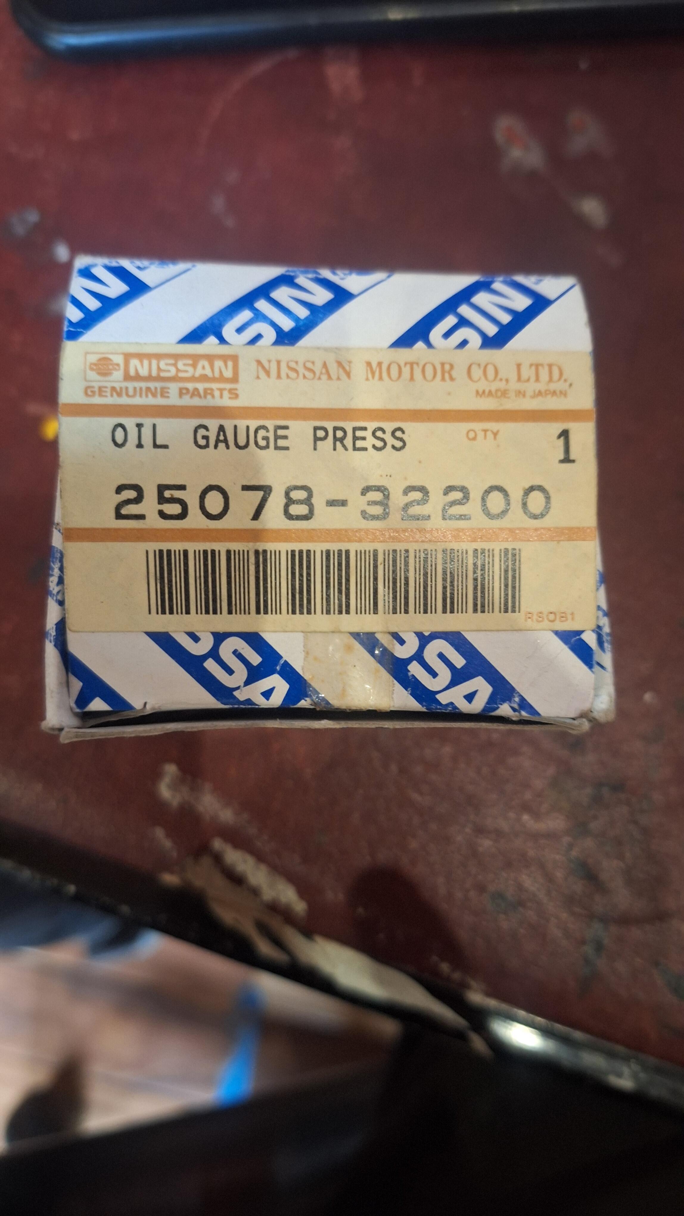
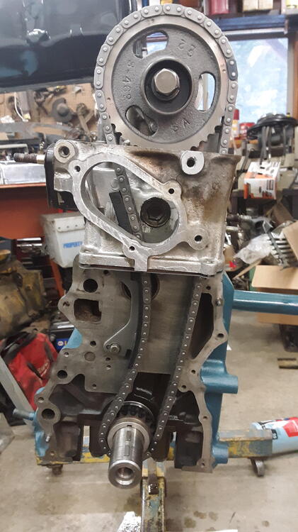
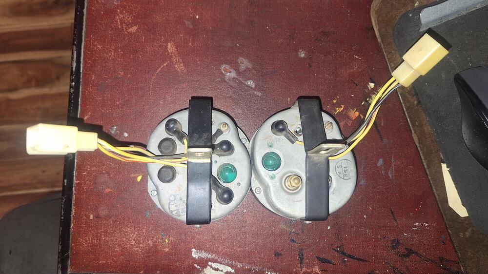
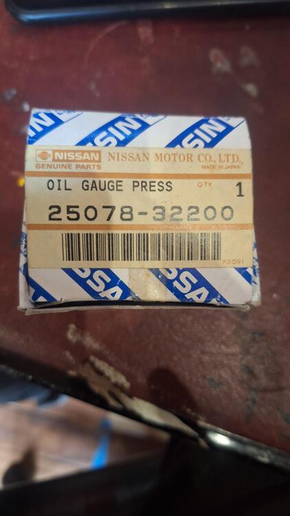
Time to put gas in it and build fuel and oil pressure. As I was siphoning gas into the tank, I decided to check the fuel gauge, turned the key, and watched my oil pressure gauge slowly rise. The fuel gauge did nothing. After freaking out a little bit thinking did I mix up the wires somewhere? Got my spare gauges out and the connectors on the back are the same, but the oil pressure/temp gauge has 4 wires instead of the 3 wires going to the amp/fuel gauge. So I stuck my head up behind the dash with a light and saw they were connected correctly. I unhooked my oil pressure wire at the engine and now I had no oil pressure showing. This car came with a NOS oil gauge press sending unit that I had installed. I put my original sending unit back on and now the gauge zeroed when I turned the key. I moved the connectors a bit at the tank, now my fuel gauge worked. The NOS gauge I had is part #25078-32200. Found out that's not for this car, maybe for a 280z. If anyone needs it, I don't. I removed the spark plugs, the valve cover and cranked the engine over. No oil getting to the cam oiler, which is a Michael Yoes upgrade. I did a little research here and someone mentioned galley plugs. That's the first I've ever heard of them. Were they removed and if so were they replaced? I don't know. I called my machinist who did the block and asked him if he removed the galley plugs. He said, "of course I did! it's standard procedure!" I asked him if he replaced them, "Of course not, that's the assemblers job!" Oh no! I don't remember anything about galley plugs, did they come in my kit? So, After a little more research I found out there are 2 galley plugs, 1 in front, 1 in back. I found a picture I took of assembly, the timing chain, and aha! there's a galley plug in it. Found a picture of the back and the plug is there. They were never removed, thank God! I did not want to pull the engine again. So, I found a great tip here, which was to remove the oil filter. Get a piece of clear hose and stick it in the hole to the galley and shove it as far forward as it will go. Get a small funnel, and fill it with oil until no more oil will go in. I did that, re-installed the filter, and the valve cover and cranked it over. I immediately felt a change, I had oil pressure, my pressure gauge went up. I guess I had to prime the pump. Next I took a vacuum pump and sucked fuel from the tank to the filter. I removed the fuel pump and connected a hose to it into a jug of gas. Back filled it with gas and let it soak in a bit, then pumped with my hand. I had gas squirting out in force! Reinstalled the fuel pump. Cranked it over a bit until I had gas in the carbs. Got some distilled water and started filling my radiator. Used just water because I didn't want antifreeze everywhere when I found the hose clamps I forgot to tighten. Turns out, the water pump seal had dried up and water came pouring out that little hole. Several day later, which was only 2 weeks ago as of this writing, I get my new Aisin water pump from Rockauto and install it. Fill up the radiator, no leaks. It's time! I turned the key and It didn't even make 1 revolution and fired right up! Wow! It started revving up so I shut it right down. My linkages needed adjusted. Got the idle down and after adjusting the clutch a bit, drove this thing out of my shop on it's own power. Yahooo!
- Last week
-
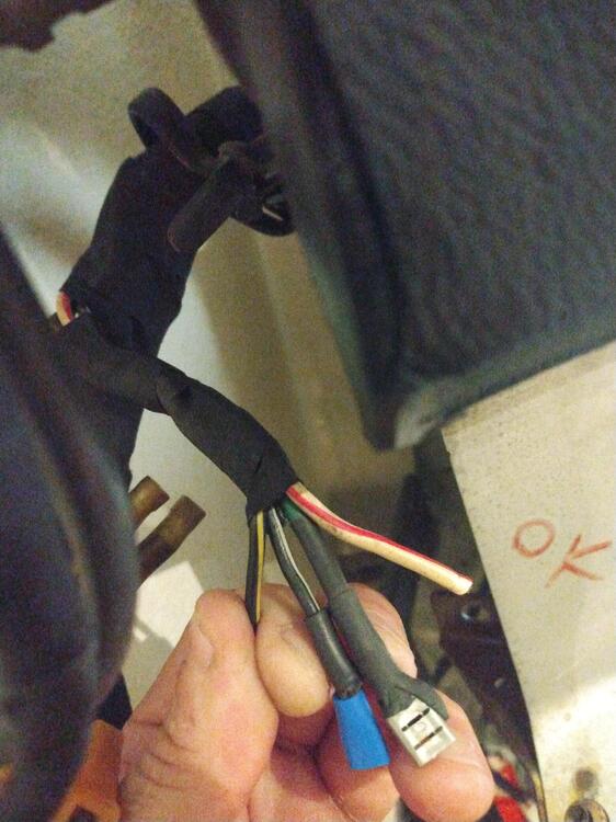
 Black/yellow - 12VDC switched from key in START. Black/white - 12VDC switched from ignition relay. The ignition relay coil is energized by the key in ON.
 -
Hi gents I'm redoing the wiring harness in my Z and hope someone could help. I've come across these wires - which used to connect to the ECU. Here's what I know Green -> goes to the fuel pump Red/White -> 12V from the battery The two that I don't know are the black/white and black/yellow. From this diagram it looks like the black/yellow goes to the ignition switch among other place and the white goes to the ignition relay and the "IG" part of the fuse box. So would these be 12V switched? I am a bit confused. I've attached photos of the wires themselves as well as the part of the diagram where they are. Any help would be wonderful! Thank you Jan