All Activity
- Past hour
-

-
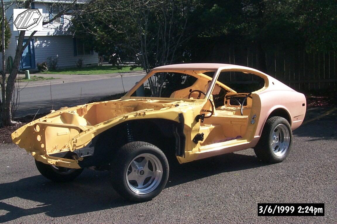
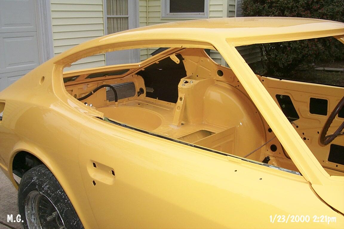
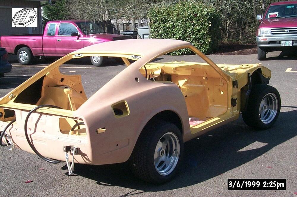
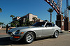
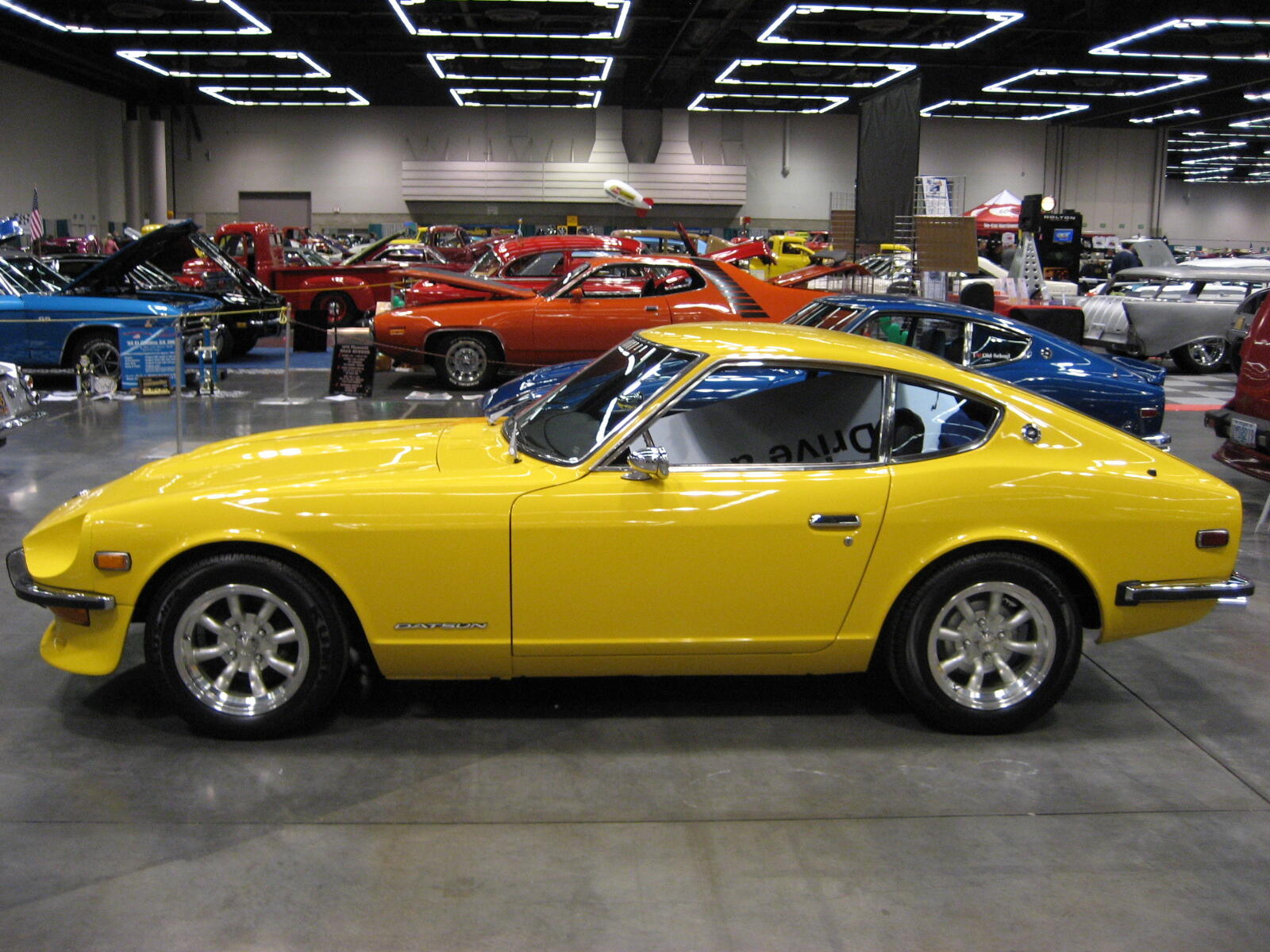
 Some additional photos... rear tail light panel is now the correct color. ;)
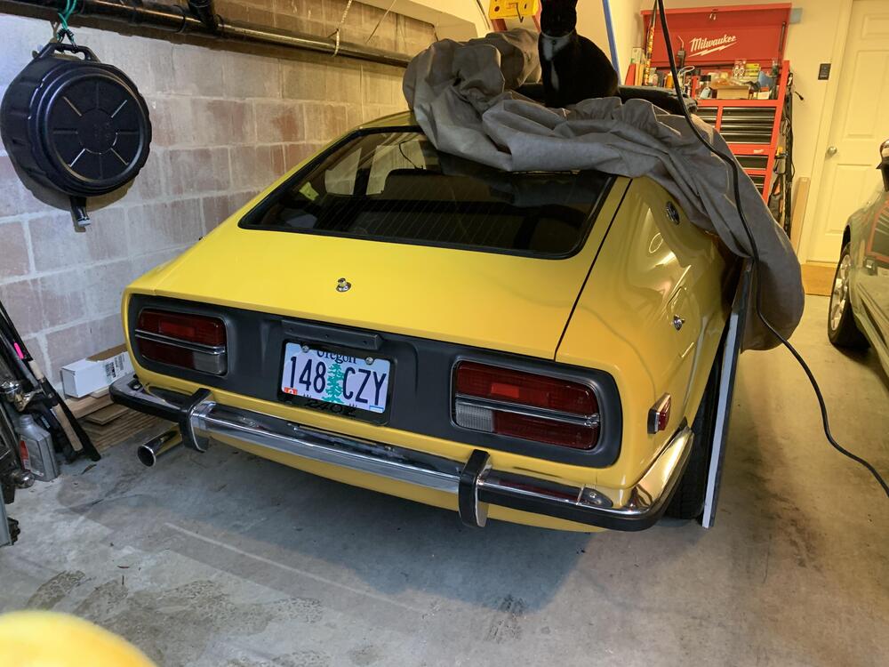


.thumb.JPG.74587a1fe53f3fe2b3d6406c75324f80.JPG)


-
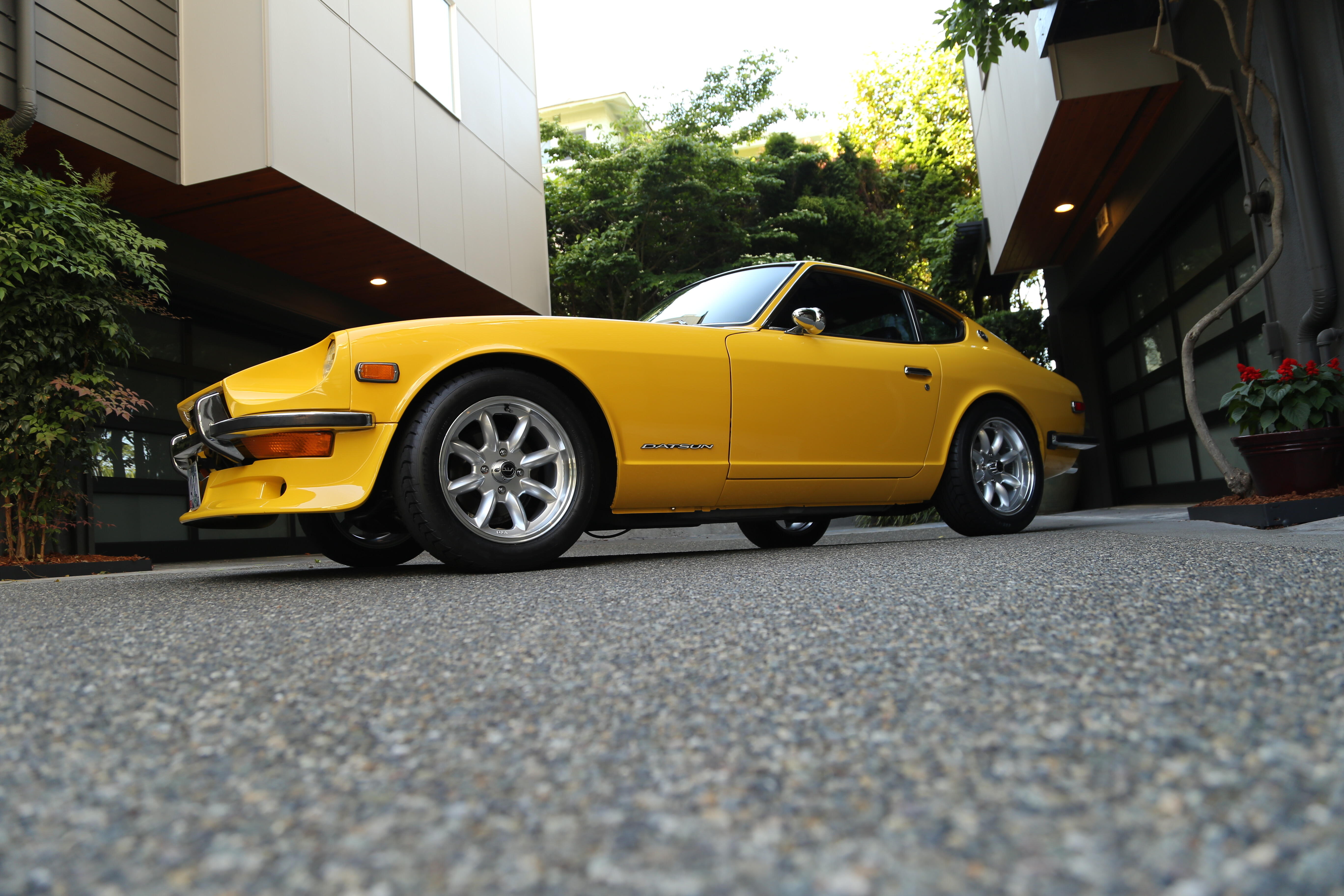
You guys recommend any changes to bring more value? I've been thinking about stock front nose (getting rid of the airdam).
- Today
-

-
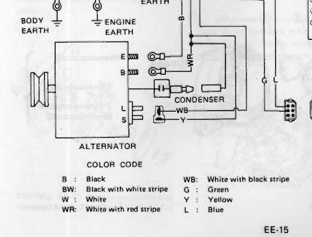
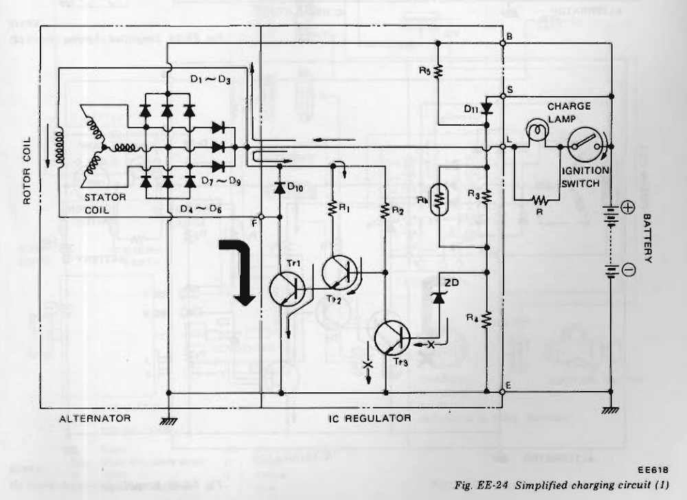
The Dave Irwin adapter converts one of the 71 wires to an "L" wire. Here's a schematic from the 1978 FSM. 1978 was the first year of the internally regulated alternator. Interesting (to me), I just noticed that there is a resistor inline with the charge lamp. In the past I think I've seen discussions about what happens to charging if the lamp burns out. Apparently, nothing. Charging still happens. In your case, when the diode opened, there was no current through the stator coil. No magnetic field was produced so no charging happened.
-
 So, while the failure seems possibly diagnosed, lets talk about why. What makes the alternator stop charging if that diode burns out. I have been looking a LOT at a 72 wiring diagram (I do not have a nice color 71 Z wiring diagram). I am trying to find something that looks like a feedback loop with a sense input, internal regulation and finally, output happens. I assumed the white wire with the red stripe coming out of the back of the alternator was the output voltage back to the fusebox and battery respectively. Is the T connector used in the feedback loop which tells the alternator to 'activate'
 -
I already have another MSA alternator kit coming from MSA as we speak. It will be here in a few days. When I was just SURE it was the alternator I ordered one. But now it may look like I have a spare. It will come with the bypass clip for the Voltage regulator and I will swap it out then. If I had a spare diode laying around I could just solder up one with clips, but I am pretty sure I do not have one.
-
The other components, the rest of the system overall, could be tested by bypassing the diode. A simple jumper wire or alligator clip could do it. Probably have to kil the engine by pulling the coil wire. Then - how to fix it. What type of diode, how to solder or crimp? Or just buy another from MSA.
-
 A possibility of fuel starvation. The end of the return of the fuel rail is restricted so there is some back pressure on the supply side to the carbs. If the lines were reversed that back pressure won't be there to feed the carbs.
 -

-
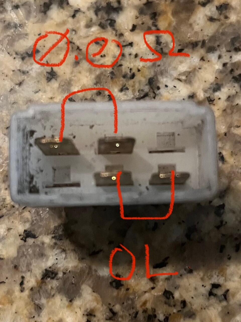
Okay, I went into the electrical lab at work and borrowed a Fluke. with the Multimeter on Ohms, with the leads going red to black (left to right) on the two pins with the diode the Resistance is 23M Ohms with the leads going black to red (left to right) on the two pins with the diode the Resistance is 1 M Ohms I then switched the Multimeter to Diode Tester. Red to black or black to red the Multimeter read OL.
-
-
The two ways a diode can fail: Open or Closed. Open: Detection - You will see infinite resistance (OL) no matter what orientation you use with your meter leads. (Always try both directions.) Result - The alternator won't charge. Closed: Detection - You will see zero (0) resistance no matter what orientation you use with your meter leads. (Always try both directions.) Result - The alternator will charge, and the car will probably try to keep running with the key off since this will backfeed the ignition circuit.
-
-
-
-
 What kind of problems?
 -
Well in Panama we have 91 and 95 octane ethanol free gasoline. My car has the original manifold. I only have heatshield installed under the carbs. Maybe its time to consider ceramic coated headers. Thanks for your advice.
-
$25,500 For instance, Less fees. Not a chance IMHO. Sell it privately to someone that’s going to preserve it.
-
-
Where did you take the alternator to be tested? If you don’t have someone at a parts store that’s competent on testing you might want to go to a local Napa store or an establishment that has a machine shop. Counter people look at a screen and most don’t have experience on working on vehicles. My HO. Ok I vented. Wish luck friend.
-
 I would think BaT with a healthy reserve. I wouldn't consider a no reserve auction, too easy to lose it cheap.
 -
Now I have no idea what the test read, as it only comes back with a big green check. No voltage out put was displayed. According to the 72 Z wiring diagram the red/white wire runs back to the fusebox, so that seems like it should be supplying the car with power after the car starts. My problem is that the wiring diagram shows the voltage regulator and I am running an internally regulated alternator. So I have to figure our which wire it is that should be charging my battery and which is supplying the car with power (me thinks red'white)
-
The alternator tested a big green check at the parts store. However, I tried to test to find any out put from the T connector while the alternator was running well I got nothing, but it would see that it fried my volt meter LOL LOL. I am sure I should have measured the red/white wire from the back of the alternator instead. But now I have to get a fuse for my voltmeter or a brand new voltmeter... which would not be horrible.
-
https://bringatrailer.com/listing/1972-datsun-240z-358/


.JPG.6b3f4f74bdb8fad357379e8c62098764.JPG)