Leaderboard
-
in all areas
- All areas
- Adverts
- Advert Questions
- Advert Reviews
- Items
- Blog Entries
- Blog Comments
- Files
- File Comments
- File Reviews
- Events
- Event Comments
- Images
- Image Comments
- Albums
- Album Comments
- Topics
- Posts
- Articles
- Article Comments
- Wiki Entries
- Wiki Entry Comments
- Wiki Entry Reviews
- Status Updates
- Status Replies
-
Month
-
All time
October 25 2006 - November 21 2024
-
Year
November 21 2023 - November 21 2024
-
Month
October 21 2024 - November 21 2024
-
Week
November 14 2024 - November 21 2024
-
Today
November 21 2024
- Custom Date
-
All time
Popular Content
Showing content with the highest reputation since 10/21/2024 in all areas
-
Hey fellow Z heads. It's been a long time since I logged in here much less made any posts. I thought I would check in to see who is still here from the old crew of 10+ years, actually it's been almost 20 since I first posted on this site come to think of it......and say hello to those who are new since I was last active here. SInce then I've gotten married, have 2 grandchildren, moved from Santa Cruz, CA to Auburn, CA and switched companies and focus. I haven't lost the bug but life, family and career had to take priority for a while, however I'm planning to dedicate more time to the hobby and hope to start reassembling the Z and get it back on the road in the coming months. Actually. I have both the Z and a 1967 Camaro RS/SS 396 to get back on the road and both need some electrical and mechanical work. Wish me luck and more importantly the time and dedication to get it done. I hope you're all doing well and spending plenty of quality time with your Z (and your families 😉).8 points
-
6 points
-
From 1969 up, Japan. The basic design of the lamp unit incorporates the two bulb holders. Japanese market models used the second bulb holder for the parking lamp system and the designated sub harness hooked it up. . Slightly later, Australian market cars got a two bulb system with a divided half amber and half clear lens and an internal partition.6 points
-
6 points
-
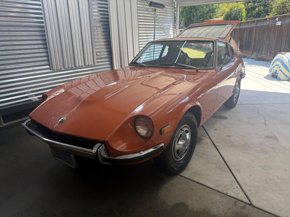
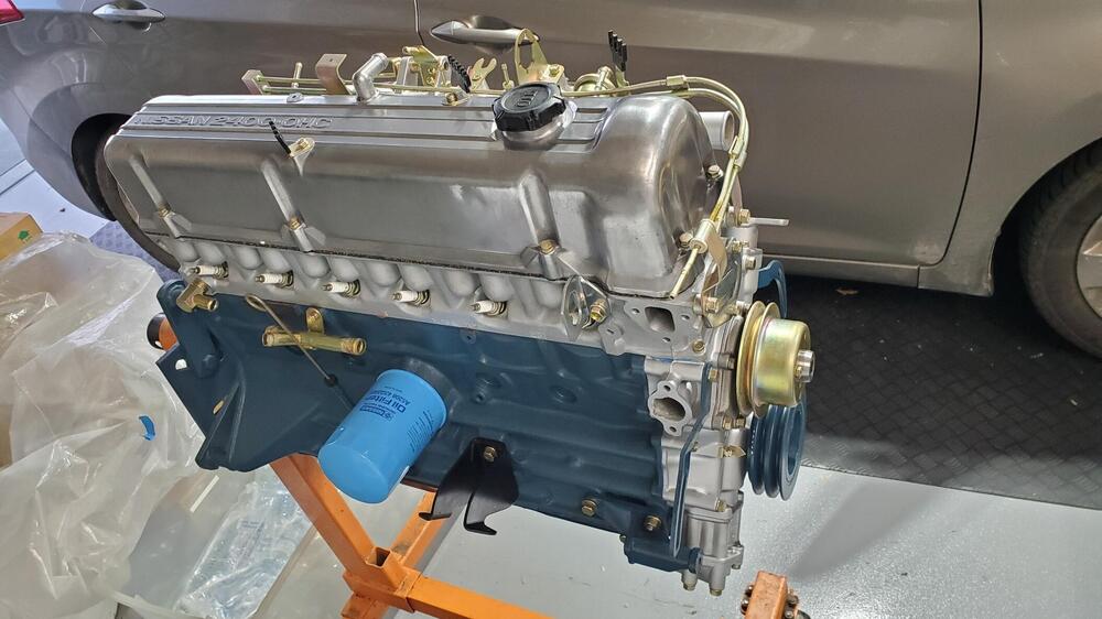
HLS30-00042 arrived this afternoon for a complete restoration. Boy, this an early one, complete with the original clear rear window. It's a little beat up, but most of the parts are there. I own HLS30-02614 in the same color, so by the time I am finished they should be looking like twins. The motor runs, which is great, but it will undergo a complete rebuild. Amazingly, the head still has the overspray on the lower portion, which is pretty rare to see. I will see if the machine shop can leave that intact. There are still a few wire clamps in there and the owner has a metal fan (and a number of other key parts), so we should be able to get the engine bay looking like the original. Looks like the hood has been replaced by a later series that was orange. The drivers side door may have been replaced as well, as there appears to be blue paint under the Safari Gold re-spray. Also, the rear panel under the rear bumper is pretty beat up and front bumper is missing. We will need to get one of those. Rear bumper looks to be in pretty good shape. Both headlight buckets are fiberglass and cracked. Both fenders are pretty rusted out in the standard places. Rear hatch panel is also rusted out (as usual) and will need to be replaced by the body shop. The interior will need to be completely restored as most items are severely cracked or worn. The original dash has just one crack in the middle unfortunately. Not sure if that is repairable, I will have to look into that as the single crack is about 2 inches long. The seats have the original vinyl material which is cool, but not usable obviously (from the pics). So the plan here is to completely strip the car over the next two weeks and get the body to the body shop ASAP as that is typically the long pole in the process. I am estimating about 6 months for the body shop to complete all its work. While the body is out, I will send the block and head to the machine shop to get that all in order for me to re-build. All the undercarriage parts will be sent to the powder coater, and all of the nuts and bolts will go out for re-plating. I will re-upholster the seats, clean up the wiring harnesses and replace the connector housings, and then start re-assembling items as they return from the shops so that once the body arrives, everything will be ready to assemble. I will post progress on here and pics as things move along. As always, feel free to comment.5 points
-
5 points
-
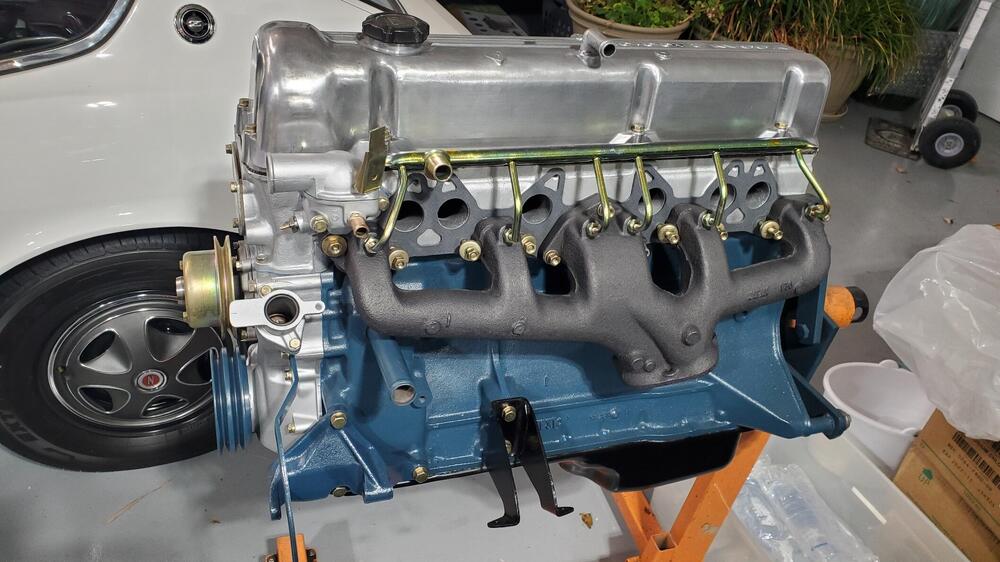
So I debated trying this or not. I'm glad I did though So the water tubes in the intake manifolds have been there for 50 years; steel in aluminum. They are 19mm (3/4") I don't have a flare nut wrench that large. But I took the propane torch to it and they came out! This is the end of the water tube. There is a rubber o ring that goes against a conical seat at the bottom of the hole. Then I used the induction heater to try to get the nuts off the pipe They came off which was great! That tool is really impressive in what you can get apart. Then I bead blasted these parts I'm glad that I did because the tube has a pin hole. I believe this would leak because the seal is a the bottom of the nut at the seat. This pinhole would be inside the nut. So I found a piece of tubing. I couldn't find anything on Amazon but I found some 10mm OD 8mm ID tubing on Ebay. So I have 20" of that coming. I will try to replate all of this in the next few weeks I pulled the studs out of the manifolds too. And this is what I had I degreased then and put them into the bead blasting cabinet. After the first pass, I turned the air pressure down to about 60psi and blasted them again. This is how they came out. I'm really pleased they look this good! Then I treated them with Sharkhide. Before and after5 points
-
5 points
-
So, I got a little education here on finding a body shop. I went to Shawn's shop yesterday and found out that he has 19 cars in his shop and 8 on a waiting list. Only saw 3 employees. He said he wouldn't be able to start work on the car for probably a year and the project would take several years. So that was a 'no-go'. I asked for some recommendations and still haven't received a call back from them. So, I was a little concerned here. This was not working out like my San Diego operation. I eventually called Guy, the 'Z Doctor' here in Boise which in hindsight, should have been my first call, and he was a wealth of information as he has restored a number of Z's here in Boise. Not only did he set me up with a body shop that has done 6 of his cars, but he also set me up with his machine shop for the engine work. What a relief! That being said, I spoke with his body shop yesterday and the guy said he would squeeze me in and should be ready for the car early next week. Will contact the machine shop once I finish the motor tear down.4 points
-
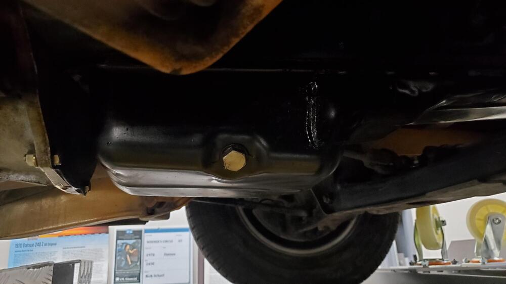
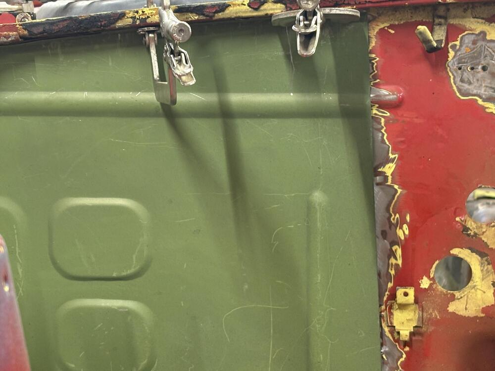
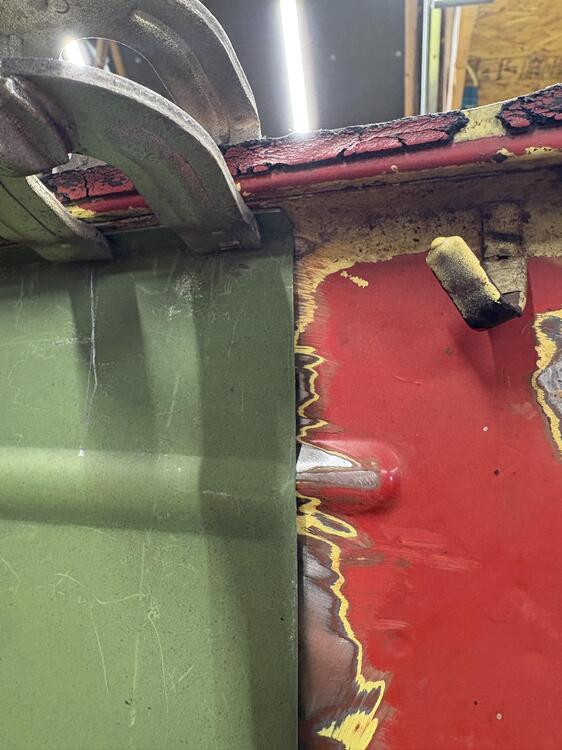
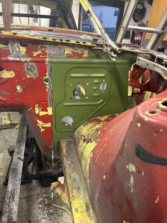
Such a dark green in contrast with thick undercoating from before. Looks much darker then anticipated, but poor lighting I believe is causing darkness…. Have a few places to touch up, maybe another coat or two, couple of runs, couple of trashy spots in the paint to sand out and re-shoot…. Still spectacular in my book…. Not perfect by any means… but sweet to see the bottom side in color.!!4 points
-
Things are moving quicker on the body front, so I've turned my attention to long-pull items which need to be ready in time for the shell's return. Tops on the list is the wiring harness, which I typically install first when a car is rebuilt. The harness itself thankfully needs limited work - it was in decent shape coming out of the car, although I suspect there are a few breaks I need to trace and take care of. I'm also planning on replacing all the connectors, as they tend to get corroded through exposure. I wont go into that process, as it's is fairly well understood by the community. The fuse boxes require a bit of TLC, however (picture 1). On my car, they are comprised of a pair of modified Niles 8-position boxes, possibly hand-made from a Niles FB87A box (or similar). Pigtail wires were soldered in place, terminating in a connector to the main harness. Some of these connectors show signs of maintenance over the many years. The lids are also showing signs of age (picture 2), so I'll put them on the 3D scan list as well. It's worth noting that someone took the time to scribe the lids with appropriate fuse sizes, which is likely unique to only a handful of early rally cars. On close examination of the boxes themselves, I found that each of the fuse locations had a pre-wired axial 12v bulb bridging the fuse terminals from the back (picture 3). Much like how a dead short blows a fuse, this outrageous modification really blew my mind - the Works team had considered the potential difficulty in tracing blown circuits and identifying shorts in dark foot wells in the dead of night. So they designed a novel solution: a blown fuse allows current to instead flow through the bulb, causing the specific fuse location to glow (picture 4). I can't speak to how well it worked in competition, but it probably only needed to work a single time during a race for the modification to be worth doing!4 points
-
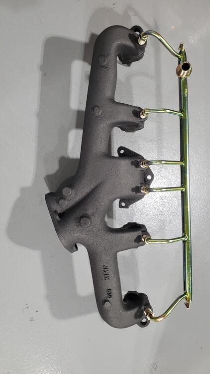
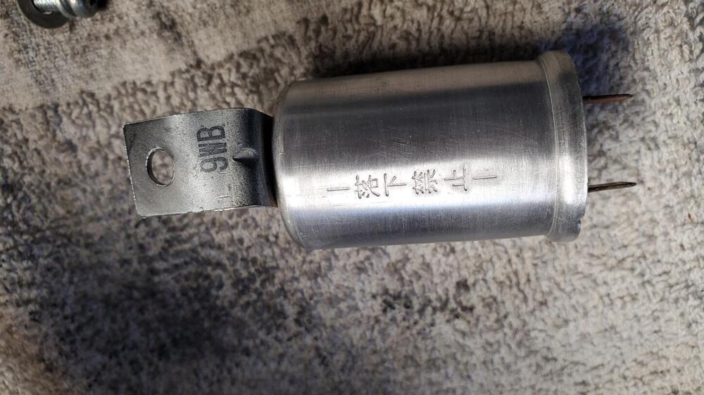
Time flies, and it's been a while since my last update. Fear not - much has been happening in the background! The shell is nearing the point where panels are being welded back on, and I'll post an update when that process is a little further down the line. Today I'll give a preliminary update on my efforts to memorialize some unique Works pieces. I've begun the process of scanning in some unique or hard-to-find parts. in some cases, this will be the only way I'll be able to rebuild the car "as original", because the original piece is so far gone that it's unusable. Such is the case of the bespoke Works exhaust header, which is a rusted metal hulk (picture 1). Thankfully, it retains almost all of its original shape, so recreating it will hopefully be a fairly straightforward process. My plan is to have the custom pieces 3D printed out of metal (such as the expansion chambers and collectors), have the flanges cut at a metal cutter, and then use relatively standard piping to recreate a near-exact look of the piece. The whole thing is likely to be made out of stainless, which I can then ceramic coat to provide a more matte period-looking finish. Stay tuned. In other cases, I'm scanning in some parts which have limited value for anyone who doesn't happen to have a 1970 MY Works car- the pieces in this category are fairly unique to the early cars, and my interest in scanning them are primarily to teach myself about the state of parts reproduction, and be able to refer to them should something go amiss, and I lose or damage the original piece. An example of this is the side jack points (picture 2). In still other cases, there are some pieces I am scanning that are actually stock Nissan Competition parts. The oil catch (picture 3) falls into this category. Although the function of this part is easily reproduced by other modern replacement parts, creating a few samples that look original might be of interest to the larger community, as even authentic competition oil catches are quite rare and expensive. Then there are the most difficult cases, free-hand creation of parts which just don't exist in the market. A good example of this are the spotlights. These Koito housings are just not obtainable- let alone trying to obtain the four required for each car- it's to the point where I openly wonder if they were ever sold to the general public at all, or perhaps just some special-order pieces supplied by a trusted vendor. Thanks to friends we all know, I have a fairly good notion of what they look like, and I've assembled a series of parts which I think I'll be able to fashion into a reasonably correct-looking "tribute" spotlight compete with "Koito" glass lens (picture 4), but without the special protective covers, which I don't think anyone has an example of. To make these tribute lights look reasonably accurate, they will require the 3-D printing of a special front bezel, which has a unique flat-face design, to replace the more conventional rounded bezels more typically seen on spotlights of the day.4 points
-
4 points
-
I have a scan of the gasket that you can print on a standard 8.5X11 page. Get some 1/8" thick closed cell foam and lay the print on it. Use a very sharp hobby knife to cut out a new gasket. I've used this process several times for license light refurb. License Light Gasket.pdf4 points
-
Seems like you might be overwhelmed with ideas. Pumping my own suggestion here, but a simple length of wire will allow you to split the whole system in half. Seems like the cheapest easiest quick and dirty diagnostic. No oscilloscopes nevessary. No offense intended to the scope suggesters. But it seems early for that level of tool. If it doesn't start, focus on everything after the coil positive post. If it does start focus on everything before. Don't forget that you'll have to remove the wire to kill the engine.4 points
-
Your L24 crankshaft can be reground to suit replacement bearings in a factory designated undersize. All details are in the factory service manuals (do you have one?). Forget about using an L28 crankshaft. It would lead to a domino effect of required parts (different connecting rods, pistons etc). Looks like you will (possibly) be needing a rebore of the cylinder block, due to cylinder bore scoring. That would require an oversize piston set. If your current pistons are still in good condition (although replacement piston rings are advised) the other option would be to fit cylinder liners. Again this is detailed in the factory service manuals. If yu are very lucky then a thorough honing of the cylinders might be acceptable. Surely there must be a competent engine reconditioning machine shop business in HK who can handle this? Looks like your camshaft is an aftermarket (higher performance) grind, judging by the stamps on the end of it. Was the car an original HK market version, or was it imported as a used car? The aftermarket camshaft makes me think the car has already been modified in the past.3 points
-
Inline, the back is OEM factory silver and in great shape so no need to repaint. The front needed repaint so had the front media blasted and put on 2 coats of 2K hot rod satin black, then 2 coats of the of the 2K clear matte, and waited 30 minutes between all coats to flash. The satin was a little too glossy so the clear matte gave it the perfect matte black finish. Spray max doesn’t make 2k “matte black”. At one time, I did have my local auto paint store mix the silver wheel paint for me to paint a splash pan. That silver nicely approximates the factory silver for the OEM original splash pan color as shown in this picture.3 points
-
I got into the shop one night this week. Worked on the clutch master, speedo cable and the hood release. I plated some parts last weekend for these items Here is the finished hood release When I took the end off the speedo cable, that allowed me to remove the spring and replate it Then I added heat shrink to the end where the jacket was missing and restaked it Then added a piece on the outside that is self sealing heat shrink All of the aluminum ends were bead blasted at really low pressure to clean them up. I did not put the cable jacket in the bead blaster though. You would never get it cleaned out! Finished cable3 points
-
3 points
-
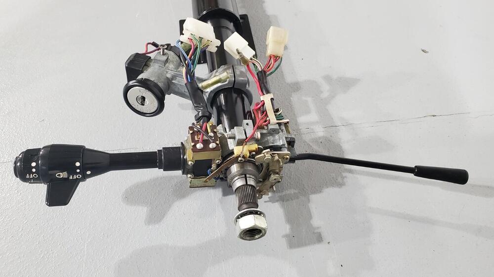
I had purchased what was supposed to be a NOS Kanto Seiki 240z ignition because it has the original steering lock buzzer wires. Turns out it’s either for something else or they increased the diameter of the steering column somewhere along the line. So since it won’t fit, and since it took the same key as my door locks, I scavenged it. Adapting the cylinder and switch to the later style housing was easy. It didn’t just drop in, but it was close. I rekeyed the cylinder with wafers I got from @inline6 and put it, the wires, and the buzzer switch into the aftermarket housing that came with my car. I was able to get a key made from the door lock code by a place in Australia called Keys4Classics. Super simple and not much money. I almost bought a rekeying kit off eBay, but I didn’t feel like spending the $80. FYI, the retailers that say they can sell them are just drop shipping them direct from ASP. I reached out to ASP directly and they said they can no longer make complete kits. The aftermarket lock cylinder uses pins and the asymmetrical oval key. The NOS lock cylinder uses wafers and the double sided VOSS key. Once everything was in hand it was about two hours of work, most of which was figuring out how to do it. The housing had to be drilled so the pin that connects the cylinder to the switch could pass through. I tried to mix and match the internals but it was sloppy and didn’t feel good, so it ended up being all of the parts from the NOS ignition inside the aftermarket housing. So now all my locks work off the same key… except for the glove box, but I have the wafers to fix that.3 points
-
3 points
-
I have a set of them. I bought their whole kit to check it out. Especially the long un-available moose-stash bar bushings. The rack bushings feel very “Stock” in my hand. I have not installed them yet.3 points
-
Damn, you have good eyes 🙂 Haha, yeah i didn't have any high expectations either. But the fact that it was officially Nissan approved made me have some hope that it's maybe better than some of the other books. Nevertheless. it will end up in my "junk" section of Z-books (which is the Majority of those books, tbh). Funny enough Flo asked the guys at Nissan germany for some press info regarding the Z and got some clearly wrongly-labelled photos from their archives). I guess this book was proof read (or not) by Nissan USA and hot any historian at NMC in JP. I keep buying and reading these books for fun's sake, but always take them with a big pinch of salt.3 points
-
Thank you for that information Gavin, digesting evidence and coming up with Nissan intentions for a “press car” without written records is hard to make it make sense 50 years later…. The combination of the red dot radio,and the captured nut for the flat hood bumper at first glance to me was a glaring contradiction. Was there a red dot rear view mirror on the hs30-00004 car. But all of these items could have been added or modified in the past 50 years as well. It is a special car no matter what…. A known z parts specialist nudged me gently,asking me if my hls30-00051 had the proper red dot radio…. Well, just not familiar with the early RDR. Looking through my am radios 1 of 5 happened to have red dot instead of the green dot…… Surprised to have this “rare” item in my stash.3 points
-
3 points
-
During my recent work at the front fender areas, i realized that the corner where the headlight buckets go on the driver side must have had a hit at some point and the panel was slightly bent backwards: I started to enjoy bearing metal panels with a hammer recently, so i got myself a proper hammer and dolly and started to hammer it straight. Worked out pretty well and i'm happy i didn't have to pay a bodyshop for another 30minutes of work. While doing bodywork anyway, i thought it's time to test-fit the rear bumper. I didn't want to mess up my NOS bumper mounts (i'll save them for the final assembly). I realized that my old ones were pretty messed up. A bit of hammering and bending and things started to look usable Then i recut the threads because the bolts wouldn't fit with the thic coat of primer that ended up in the holes: And last but not least i put some rust-converter on the straightened brackets and installed them on the rear. But i forgot to take photos of that. Then i got a bunch of panels in questionable condition from germany. What is special about those front lower valances you ask? Three of them are specific for European spec cars, with the additional mounting points for the euro-spec front spoiler: Here you can see them with my (very wobbly) front lip: I once had a NOS one, but it seems i sold it a while ago (back then i thought i'd go for the xenon front bumper anyway). and now i hate myself for it. Luckily one of the corner valances seemed to be half-NOS. It still had the original protective black primer and sticker on it, but it also had a bit of rust and remaints of a front bumper that was once attached to it. BTW: those EU-spec corner valances have a closed hole for the turn signals (we got the ones mounted on top of the front bumper) and again holes at the bottom for the front lip: Well. it took me a few minutes to get those rusty old bolts out, but now i have again a complete (albait the center part is not very fresh) set of EU-spec lower valances. Oh and a sea-freight pallette with some nice parts left the Port in Japan last week. so i hope in a few weeks i can show you some nice parts... And then, recently i iwas at a very nice S30 related event in the netherlands (more about that very soon). And there i got some nice gifts. Read more about it here: https://www.jdmjunkies.ch/wordpress/2024-10-26/240z-some-gifts-from-the-netherlands/3 points
-
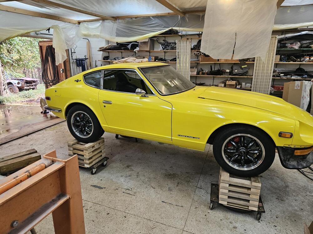
The 'B' transmission's design places the base of the shift lever further forward relative to the front face of the bellhousing, resulting in a number of complications when a B unit is installed in a car that was designed for the A unit... - Base of shift lever hits the front edge of the cutout in the transmission tunnel when 1st or 3rd is selected. - Shifter knob comes too close to the HVAC fascia when 1st or 3rd is selected. I'm curious to know how this issue was handled by the dealer who did the B-for-A transmission swap in your car. p.s. I like the wood cradle that you built to support the car. I know of another Z owner who built a rotisserie from wood.3 points
-
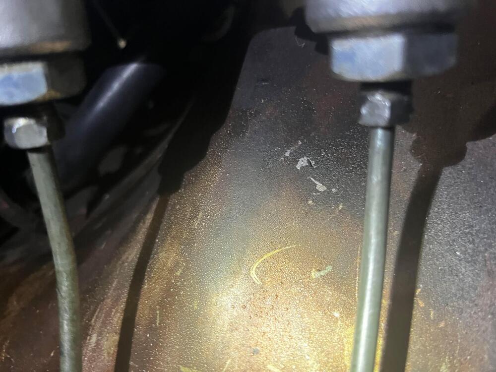
The check valve (if there is one) is built into the master cylinder. Not all master cylinders I've messed with have a check valve. Some of them have a "slows down the return valve", but it's not a full stop. Others do have a full stop below a certain pressure. On the earlier 240Z, there are two "brass devices" under the right rear*. The first is a proportioning valve, and the second one is just a dumb "T" junction point. The feed comes from the master to the proportioning valve, and the output of the prop valve goes to the splitter "T". The part that zcardepot sells is the dumb "T" splitter junction. However, neither of those brass devices contain a check valve. *Closer to the right than the left.3 points
-
3 points
-
Finally resolved the exhaust fumes in car issue - I added the downturn tailpipe (2.5" SS ) I found either on here on another Z forum, I forget. Drove it around to determine if it worked - it did - so I tacked it in place Didn't care for the look of the single tip, so I added a fake next to it, staggered slightly Much happier driving around now, can have both windows open! 😀3 points
-
Exactly. I'm not quite 1925 old. That was my Dad. I was raised in the 1950's and 60's... 2 cents is what we got for each pop bottle we found on the roadside and turned in at the store. A little collecting and you got a pretty good stash of penny candy - or even a candy bar for a nickel...3 points
-
I think the float bouncing around is part of it. I also think that you can get on the downhill slope of the float tang, and once that happens, you're doomed. Wideband testing would be cool. I know there are people here that think the mixture ratio is highly affected by the float level. I'm not one of them. I believe float level has an effect, but I don't think it's that stark. Of course, however, without testing data, neither camp is anything but speculation. Wideband data would be very interesting.3 points
-
I'm old. When I was a kid we could get 4 hamburgers for a dollar. Ever heard of "penny candy"? We used to buy it... Between then and now my "2 to 45 cents" is probably way wrong...😉3 points
-
Something like this perhaps? https://belmetric.com/m8-slotted-grub-flat-point-set-screw-brass/?sku=SS8X10SLFLATBRS or perhaps stainless would be better because it is heavier: https://belmetric.com/m8x1-25-a2-stainless-iso-4026-flat-point-allen-socket-set-screw/? And what are your thoughts about drilling and threading up the center of the float on the bottom surface? Using the same logic you mentioned, if it were to back out, it would either drop out (and lower the fuel when it does), or contact the bottom of the float bowl, and hold the float up higher, dropping the level of the fuel.3 points
-
Not finding needle valves readily available was probably a good thing. I probably would have ordered them, however, I went out to the garage and took the float cover off again and inspected everything again. This time I used about 10 psi of compressed air and checked to sealing. The float was turning quite a bit angled in order to get it to seal. That doesn't make sense to me. I don't get why the floats aren't more level at the point where the needle seals against the seat. In this case, the bottom edge of the float appeared to be crossing over where the side of the float bowl would be (if the cover was on the bowl). Perhaps the side of the float was interfering with the side of the float bowl and not able to rise more to seal the needle against the seat. Though I used the clear tube method to set float levels previously, I repeated that process tonight with this carburetor bowl, and again set the float level so gas came up to a mark I set at 20 mm from the bottom edge of the float cover. Is 20 mm from the bottom of the lid is correct? The needle and seat is working properly again now. I took the car for a another brief 3/4 mile drive. It was not fully warmed up, but it ran a bit better than before at 2.5 turns out on the mixture screws. Assuming I don't run into another issue, I will get it up to temp and try another brief road test tomorrow to see if I will be able to get the mixture close by backing out the mixture nuts a bit more. Perhaps I will need to switch to different needles. I don't know.3 points
-
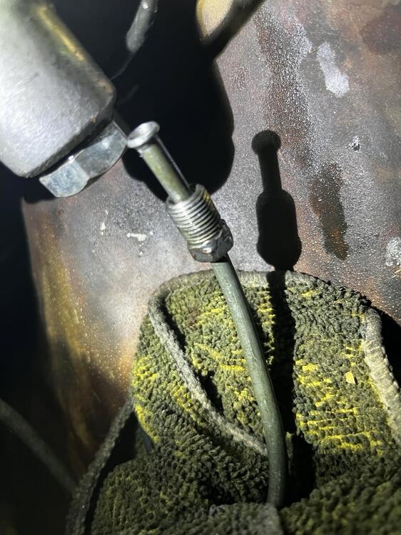
So... I ran into the same thing with the clutch master cylinder tonight. This cylinder was a used part also. It looked to me like it was replaced by the previous owner as part of the fresh work he did to the car. Hmmm - actually, I think that was 28 (plus 6 years in my possession) ago! Anyway, the little valve was stuck in this one also. For any used cylinder, that valve should be checked and lubricated with a bit of rubber grease before installing the cylinder. I was able to get the clutch operational, and the brakes barely so. I need another person to assist to bleed them properly. And it is quite possible that the brake booster is not functional. Anyway, I took it for a brief drive in the neighborhood. It has been about 9 years now since I drove a Z. It's tiny! Turning around to back up, I was struck by how narrow, and also, how little there is of "car" behind me! I was reminded again of how awful the throttle linkage is. It has a lot of initial resistance, so you press a little harder, and then a little more, and then it "let's go", causing more acceleration than intended. As I recall, I will be able to sort that out by adjusting the linkage and bending the gas pedal arm as necessary. Oh, and that exhaust stink. Hahaha! Even when you get them running well, if you spend much time behind the tail pipe, you stink like you've been running a 2 cycle leaf blower. While it starts up easily and has good throttle response, it doesn't sound or feel like it is tuned. When I give it enough throttle to go past 2500 rpm, it acts like it is lean - it doesn't want to rev. I will need to check timing again (static and dynamic), and check set/mixture screws again, carb sync again, etc. Anyway, it runs!3 points
-
I finally got around to doing the plastic trim and tried this rad paint alongside the traditional SEM way. The SEM way was much simpler than I had imagined and the results were fantastic, practically factory fresh. I followed this demo from the product https://semproducts.com/product/color-coattm-mixing-system/system#product-videos I just did one of the rear panels and it literally took me 20 mins from start to finish and that includes total drying time and ready to install. Sounds crazy, but really it was that easy. If anyone still needs to do this here are the products I used I started from left to right, hosed it and washed it with the soap and pad. Dried it then wiped it down with the plastic prep and it quickly evaporated on its own. Then a quick thin coat of the promoter and quickly followed with several light coats of the landau black. Below is a picture of it fully dry, this is not still wet it literally dried in like 60 secs basically bonding to the plastic.3 points
-
2 points
-
Hi Gavin, I posted this some time ago, a Z432 has plastic tabs for its lids. This car has April 1970 seat belt tag. On the other hand, the green BAT 310000 USD 240Z has metal crips was manufactured date 05/70. So we can say there is a border line between them. BTW, I also posted this, 4 steps evolution of inspection lids. Kats2 points
-
2 points
-
Actually managed to find the images of other early features on HS30 0004. Plastic clip inspection lid AM Radio - no signal seek function and no power antenna switch (similar to Fairlady Z-S specification) Early style ventilated (hat) brake rotors. But here is the curve ball, since HLS30 in 1969 had the solid rear glass, no defrost glass. But HS30 0004 is different. Temperlite stamp Rear view mirror date stamp and horn date stamps And the sump plug and sump (welded in sections)2 points
-
With the "wet set" method, I was setting them in the installed state, adding gas through the inlet to the float chamber. I was setting the height of the fuel (as seen by looking at the translucent nylon tub attached to the float chamber outlet) to 20 mm below the casting separation line of the chamber and the lid. I switched to setting at 14 to 15 mm between the bottom surface of the float chamber lid to to the top of the metal portion of the float. I did this by cutting and grinding 2 3d size trim nails - one to 14 mm in length and one to 15 mm in length. Using needle nose pliers, I hold each and place them vertically aligned between the float and the roof of the chamber lid. I hold the float pressed against the nail, pinching the nail (vertically aligned) against the roof... and I blow into the fuel inlet. Using the 15 mm nail segment, air can flow from the inlet past the needle valve. Using the 14 mm nail segment, it cannot. I used this method with the rear carb only. I did this yesterday. Today I started the car and the fuel did not gush out of the vent in the chamber lid. I did not run it long or do a test drive. FWIW, this second method is what I always used for my other Z when it had SU's on it. I never had problems with either fuel overflowing or performance, for that matter.2 points
-
Just checked my stash. Have NOS sets dated coded 1972 and a 1973 set, white lettering. Also a set of unstamped ones I'm doing up for my car in yellow lettering for 1970. Don't have time to do the reproductions, busy developing next gen drones!2 points
-
2 points
-
They are in Canton. I used them a year or so ago. They rebuild your unit. I think it took a week or so.2 points
-
Don't let your wife read that! https://atlanticz.ca/zclub/techtips/ aka "Blue's Tech Tips" and this forum is all I needed and I don't have any cents.2 points
-
Yes, I believe a commercial setscrew type of device would work just fine. But as for the material composition... I believe that brass has a higher density than steel. So if your steel on is heavier, that would only because it's longer: https://www.engineeringtoolbox.com/metal-alloys-densities-d_50.html https://www.engineersedge.com/materials/density_of_common_engineering_materials__15896.htm As for screwing it up into the bottom of the float, that would also satisfy the failsafe of closing the valve instead of holding it open. Only reason I didn't do that is I wanted gravity to have as little effect as possible on pulling the insert out of the float. I figured that gravity would have less of a tendency to pull it out if it were stuck into the side. Not that I really expect that gravity could possibly pull it out, but put it on the side just to be sure.2 points
-
2 points
-
Took another look at the carburetors tonight. Neither piston was dropping to a "clunk" in the carb bodies. The needles were touching the nozzles, and that was keeping the pistons from going to their correct locations when doing the "piston drop" test. I was wondering why my idle speed kept moving around! I loosened the nut holding jet bridge and centered it properly on the rear carburetor. Firing it up briefly, the idle is MUCH improved. I will do the same for the front carb and give it another little test drive.2 points
-
Thanks for that info! So, when I took the cap off, I found that the valve was stuck in an open position (makes sense if that is resting position, as the cylinder likely sat for a very long time and got gummed up/stuck in that position). The spring couldn't close it. In fact, there is a hole in the end of the cap, and pressing a flat punch against the valve, it did not move - it was stuck tight. Stuck in the open position, fluid just moved freely in both directions. The rear circuit didn't build any pressure. I just got back from the garage - I am done for the night. This time I was able to bleed the MC rear circuit with no issue. Then, I was able to bleed all four corners. I seem to have a solid brake pedal at this point. Hurrah - I got something done today after all. Now, I have the clutch circuit to bleed. And then, I'll try to fire it up and drive it around the neighborhood a bit.2 points
-
Forum Statistics
-
Total Topics66.3k
-
Total Posts661.5k
-
-
Gallery Statistics
-
Blog Statistics
-
Total Blogs167
-
Total Entries251
-
-
Download Statistics
-
Vehicles Statistics