Leaderboard
-

hr369
Community Member3Points1,240Posts -
sweatybetty
Community Member1Points1,119Posts -
Careless
Community Member1Points446Posts -

Dave WM
Community Member1Points3,591Posts


Popular Content
Showing content with the highest reputation on 09/01/2016 in all areas
-
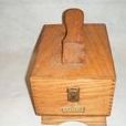
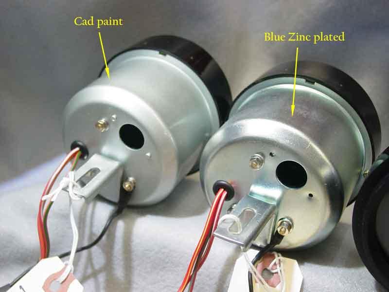
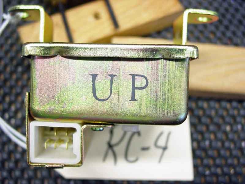
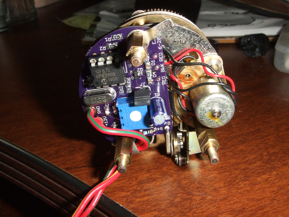
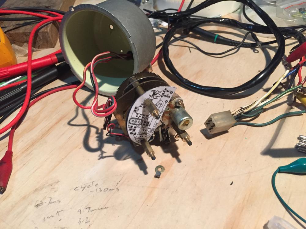
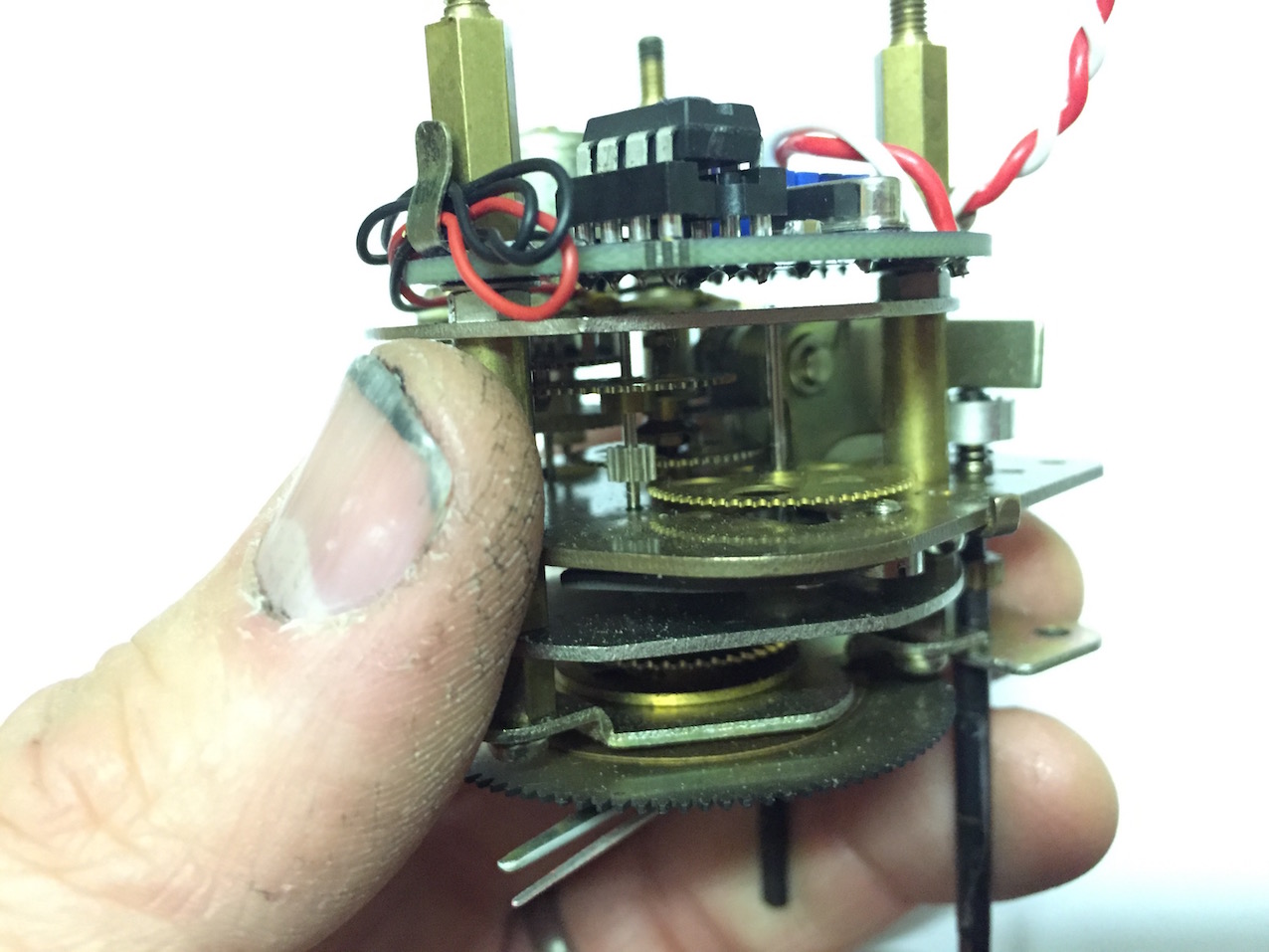
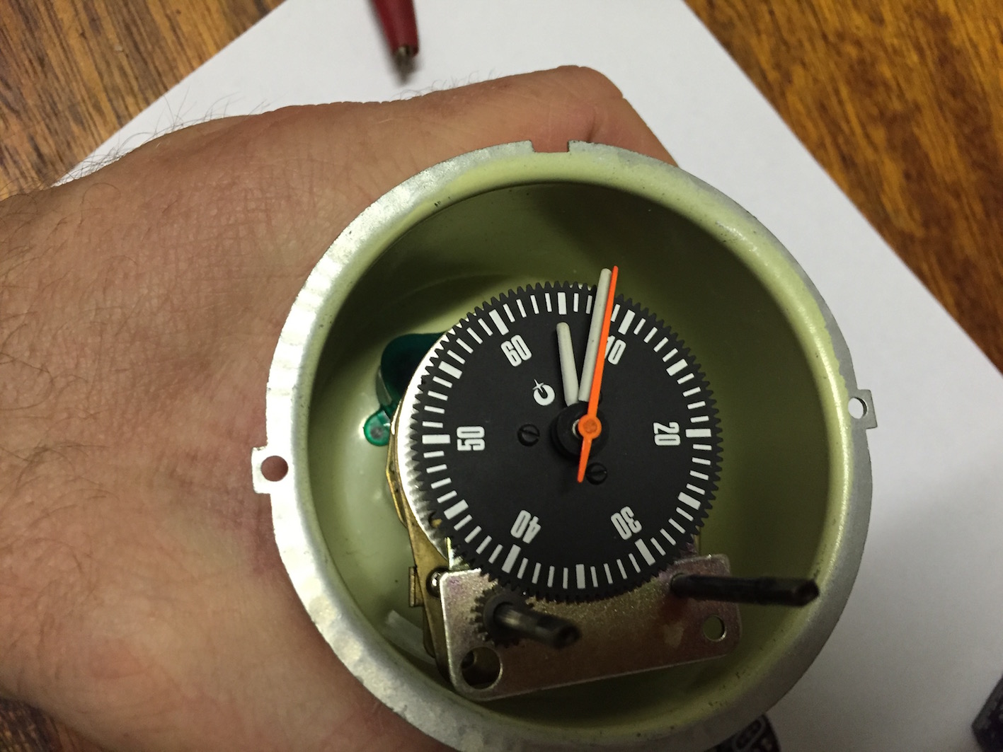
The wiring diagrams you have above look correct at first glance to me. I'm attaching a bunch of photos from the repairs that have been done to my rally clocks over the last couple of years and show a lot of detail of the internals of a Rally Clock Oscillator, 1 thing you may need is to see how the wires are aligned to the pins on the plug? I'm not sure if Ron replaced all the wires with the exact same colour coding used on the originals. I assume he did. But never make assumptions.
.jpg.865598d091dc5456fca1c6c77ed10636.jpg)
.jpg.3c8160f20d0cc41cafe2e63640f4dab4.jpg)
.jpg.d4466d7903d86d9dd83762cf8b06db11.jpg)
.jpg.81daa98527b2b50087a9019501a7556a.jpg)
.jpg.45b57c7995c158d0b938900a1e413d96.jpg)
.jpg.f1e1bad67a69814bc5d8c36c207cad81.jpg)
.jpg.d18e9b9eb5ceb4904d8b9e056ab0d1fd.jpg)
.jpg.dfd008eff0ca9b7a0e547a189d38edaa.jpg)
 1 point
 -
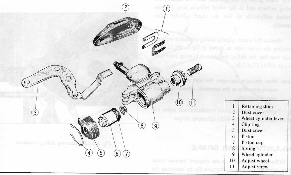
1 pointit looks like the adjuster and parking brake hardware, not the bleeder
 1 point
 -
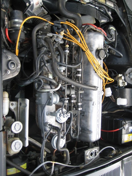
1 pointIt's on page 194, "High-Idle Problems". It says that the symptoms were mostly for extreme cold weather, warm climate Zs possibly escaped modification. Here's what I followed on my early '77. It's a '78 motor picture. I didn't use the hardline to the AAR just a longer piece of heater hose. I don't know why it's sideways? Not like that until I uploaded it.
 1 point
 -
Good luck with it, I am pulling for you!!1 point
-
1 point
-
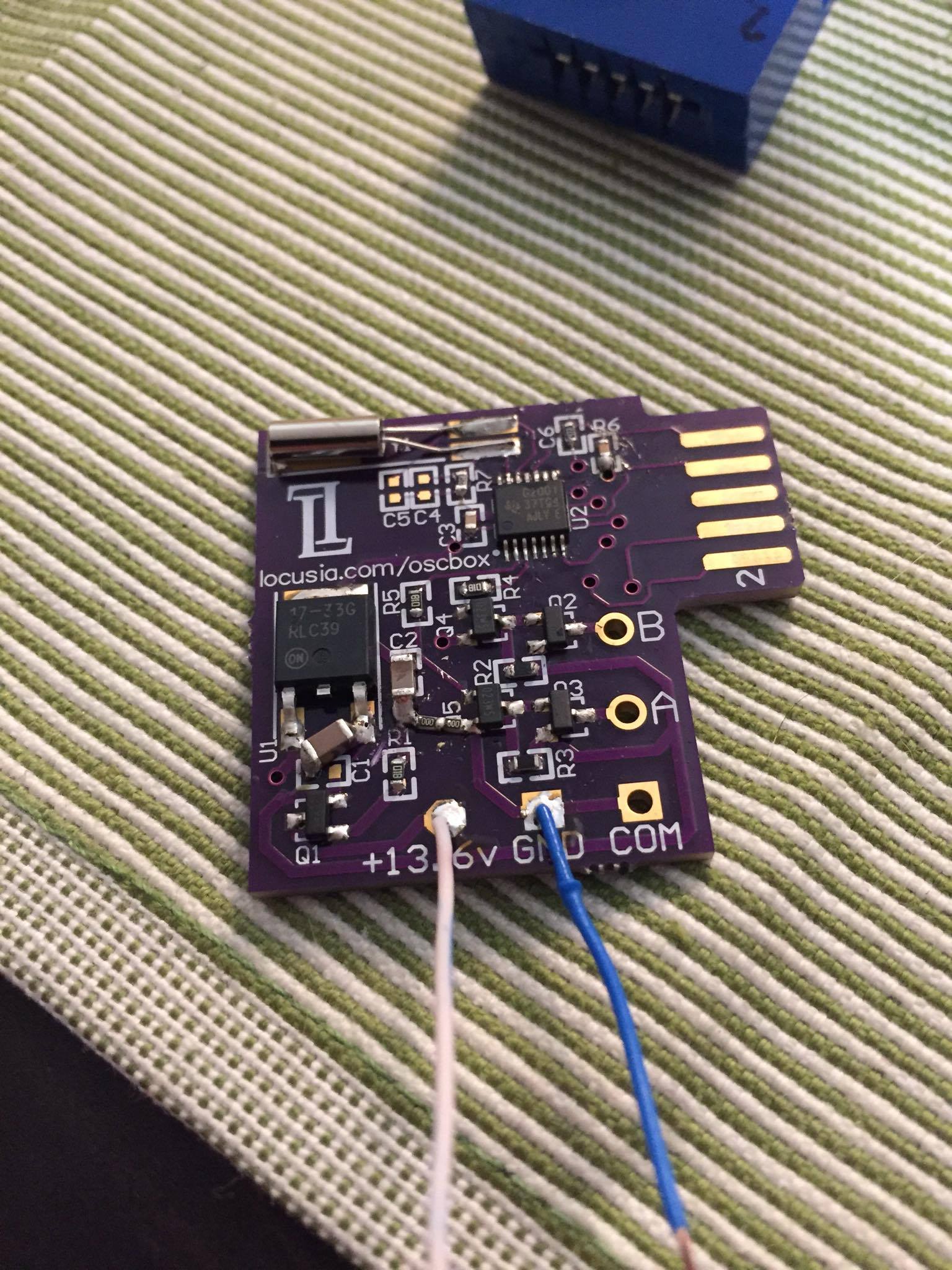
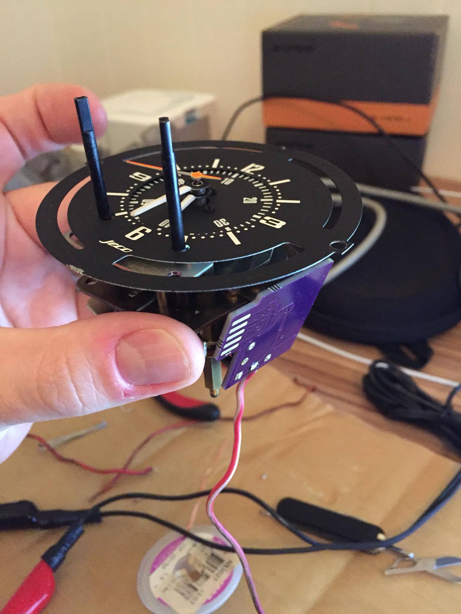
Update time. I've received the purple pcb oscillator and installed it. It's way smaller that it looks in the pictures. It took about 20 minutes to solder in the new board and bolt it in. I will be testing it with my other clocks to see how accurate it is. Right now i've had it running a couple hours and its keeping accurate time. It has built into it, reverse polarity protection for those of us that are electronically challenged, myself included. I've ordered a small amount of boards as I don't anticipate many people will need them. clock running with new purple oscillator Reverse engineering this clock and running it on 21'st century electronics was no small feat. Here is some of the C code that Eric wrote for the prototype and resides in the little IC chip. AWESOME work he does. __________________________________________________________________________________________________________________________________________________ #include <htc.h> #include <xc.h> //#include <float.h> // do I need this? #define _XTAL_FREQ 4000000 // Internal Oscillator... for now. Required // for __delay_ms function /* The configuration bits can be set in the IDE 'Configuration Bits' window, * or they can be set here. */ // PIC12F675 Configuration Bit Settings: /* CONFIG */ #pragma config FOSC = INTRCIO // Internal oscillator. #pragma config WDTE = OFF // Watchdog Timer disabled. #pragma config PWRTE = OFF // Power Up timer off. #pragma config MCLRE = OFF // MCLR pin disabled, I/O function of GP3. #pragma config BOREN = OFF // Brown-out detect off. #pragma config CP = OFF // Program memory code protection off. #pragma config CPD = OFF // Data memory code protection off. unsigned int pulse_width_count = 0; // Used to adjust pulse width. volatile unsigned int T_pot_setting; // Most sig 8-bits from pot ADC conversions. volatile unsigned int F_pot_setting; // Use all ten bits, so need 16-bit word. volatile char outputs; // bit0 for output 0 (GP0), bit1 for output 1 (GP1). volatile unsigned int analog_reading; // The 10-bit ADC result. /********************************* SETTING UP ************************************/ /*********************************************************************************/ void init_ports(void){ // Set input & output pins: GP2 (AN2) and GP4 (AN3) set as inputs for analog signal, // GP3 can only be input. TRISIO = 0b00011100; // Comparators off. CMCONbits.CM = 0b111; // Analog input register ANSEL set in setup_ADC() below. } //////////////////// void setup_osc(void){ ; // Nothing to do here. The oscillator is set above by setting the FOSC bits. // OSCCAL = 0x00; // Shouldn't be needed. } //////////////////////// void setup_timer1(void){ // Timer1 is 16-bit. It will count to 65535 before overflowing. // With a 4MHz internal clock (Fosc), the instruction clock operates at 1MHz: // (Fosc/4, so Tcyc = 1usec). // With a desired interrupt time of 11.43msec, we have 11430 instruction cycles, // which is under the 65535 cycles possible with Timer1. So using Timer1 should be // fine! T1CONbits.TMR1ON = 1; // bit 0 = 1: TMR1ON -> turn timer on. // bit 1 = 0: TMR1CS -> Clock source = Fosc/4. // bit 5,6 = 00: T1CKPS -> prescaler = 1:1 - no scaling. } ///////////////////// void setup_ADC(void){ // Pulse_Width is analog input on AN2. // Pulse_Frequency is analog input on AN3. // Set ADCON0 configuration bits: // ADFM = 1 : ADC result right justified as we will use all ten bits. Two most // sig bits in ADRESH, the eight least sig bits in ADRESL. // VCFG = 0 : ADC reference is Vdd pin.. for now. // <CHS1:CHS0> = 0b10 (2dec) to select AN2 input, (<CHS1:CHS0> = 0b11 3dec) for // AN3 input. // ADON = 1 : Turn on the ADC. ADCON0bits.ADFM = 1; // ADC result right-justified. ADCON0bits.CHS = 3; // Select AN3 for ADC for first conversion (freq). ADCON0bits.ADON = 1; // Turn on the ADC. // Set ANSEL configuration bits: // <ADCS2:ADCS0> = 101 for 4us TAD conversion time (datasheet recommended for 4MHz // clock). Analog input on AN2 (GP2) set for pulse time adjustment pot, and AN3 // (GP4) for frequency adjustment pot. ANSELbits.ADCS = 0b101; } /**************************** INTERRUPT SERVICE ROUTINE ***************************/ void setup_timer1_interrupt(void){ // Timer1 is a peripheral, so peripheral interrupts must be enabled // (and also global interrupts). TMR1IF = 0; // Clear Timer1 Interrupt Flag. PIE1 = 1; // Enable Timer1 Interrupt. PEIE = 1; // Enable Peripheral Interrupts. GIE = 1; // Enable Global Interrupts. } void interrupt ISR(void){ // Interrupt Service Routine // This interrupt it called at twice the motor (electrical) frequency. // Timer1 has timed out so we must aternate the GP0 and GP1 outputs. // The interrupt activates on overflow, so the starting value of the timer // must be determined to get the correct timer period. Calculations at end // of code. // Here we read and manipulate the last ADC result and initiate the next ADC // conversion. We will perform ADC on the two analog inputs alternately // (one for pulse frequency, and one to control the pulse width) // In reversing the pin polarity, the pins themselves are not reversed as they // might both be 0 (as the expiration of pulse_width_count will set both outputs // to zero). So 'outputs' records the last setting of output pins, and it is // 'outputs' that is reversed. This is then copied to the GPIO pin register. TMR1 = (0xDC00 - F_pot_setting); // Reset TMR1. outputs = outputs^0b00000011 ; // XOR - reverse outputs for GP0 and GP1. GPIO = outputs; // Assign 'outputs' to actual output pins. // Alternately update the Frequency setting (F_pot_setting) and pulse width // (T_pot_setting). if ((outputs & 0x01) != 0){ // Set pulse width. analog_reading = ADRESL + (ADRESH * 256); // Change 10-bit value to 8-bit T_pot_setting = (analog_reading >> 2); // value (max 255). ADCON0bits.CHS = 3; // Change A/D channel to measure Frequency pot // next time around. __delay_us(50); // Delay after channel swap, avoids cross-talk. } else{ // Set pulse frequency. analog_reading = ADRESL + (ADRESH *256); F_pot_setting = (analog_reading << 1); // Mult by 2 to scale to 0x7FE. ADCON0bits.CHS = 2; // Change A/D channel to measure pulse width pot // next time around. __delay_us(50); // Delay after channel swap, avoids cross-talk. } ADCON0bits.GO_DONE = 1; // Start next A/D conversion. pulse_width_count = 0; // Reset counter for pulse width. // GPIO5 = 1; // Turn on LED at GP5 - program running. TMR1IF = 0; // Reset Timer1 overflow interrupt flag. return; } /********************************** MAIN PROGRAM **********************************/ /**********************************************************************************/ void main() { setup_osc(); init_ports(); setup_timer1(); setup_timer1_interrupt(); setup_ADC(); outputs = 0b00000001; // Initialise output pulses variable with pulse // at GP0. GPIO = outputs; // Write to GPIO register. // Turn on LED at output GP5 - program running. while(1){ pulse_width_count++; // Delay chosen so that that 255 (0xFF) __delay_us(28); // increments take up the full 11.4 millsec. if (pulse_width_count > T_pot_setting){ GPIO = GPIO & 0b11111100; // Turn off outputs. GPIO5 = 1; // debug - turn on LED pulse_width_count = 0; // Reset so we don't keep coming back. } // if } // while } // main /* Determining the Timer1 starting value for interrupt for clock frequency: * * The clock I tested needs the outputs to be alternated every 11.43 millisec * for the clock to operate at about the right speed. * The microcontrller clock speed (Fosc) is set to 4MHz in the config parameters * at the start of the program. Timer1 increments with each instruction cycle which * is equal to Fosc/4 = 1MHz, so it increments at 1 microsec intervals. For 11.43 * millisec, the clock increments 11430 times. As the timer interrupts at overflow, * then the timer must start at 65535 (0xFFFF) minus the 11430. * 65535 - 11430 = 54105 (0xD359) approx. * The result from the A/D converter is 10-bit, i.e. 0-1023 (0x00 - 0x3FF). * This permits an adjustment time of about 1 millisec. If I want an adjustment * time of +/- 1 millisec (2 millisec) then I will double the A/D conversion result. * So the timer starting point will have to be about 0xD539 + 0x3FF, so that up * to 2 * 0x3FF can be subtracted from it. So starting point will be about 0xD938. * This is approximate as there will be some latencies in processing the code, etc * The final value will be higher and determined experimentally. So we should * have a range of about 9.4 millisec to 11.4 millisec with the 'correct' * 10.4 millisec setting when the control pot is set to the middle position. * * Determining pulse width: * * The output of the pulse width pot is saved as an 8-bit value: 0xFF (255 decimal). * At lowest frequency, the pulse width above will be up to 11.4 millisec, so we * need the pulse width counter to increment at 45 microsec at a time (45us * 255 * = 11.5 ms. An added delay of 28 microsec resulted in desired increment delays . * */
 1 point
 -
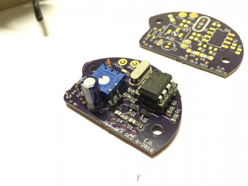
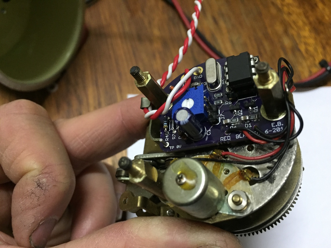
Ok, this is our version 2.0. of the oscillator. Eric is going to send me a copy and I will try it on different clocks to see how accurate it it keeps time. We have a speed adjustment pot just just like the original oscillator had just in case. Fits nicely in the place where the original smaller circuit board was. oscillator running youtube


 1 point
 -
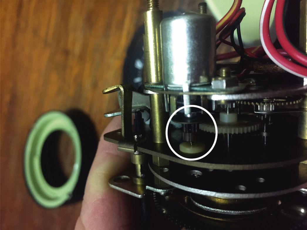
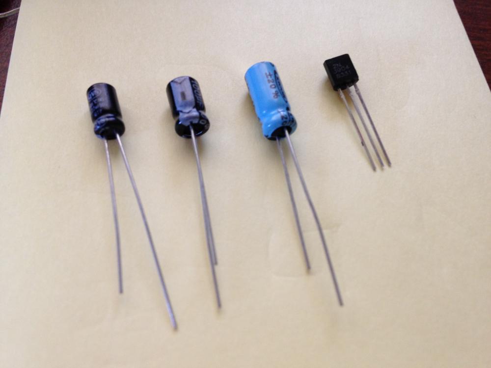
Eric has mocked up a circuit board that fits inside the clock. It seems to fit well in the location where the little circuit board was. I've assembled a kit of 3 caps and 1 transistor that are needed to fix a calendar clock and a 280z (non quartz) clock and will be selling them for $10 if anyone is interested. Pic #3 is the very fine coil wire I was referring to that is very easy to damage if you're not careful soldering in the one capacitor.
.thumb.jpg.d624ef33f6b2a5f1541cbe56e927cb37.jpg) 1 point
1 point -
Well done. You have done a very neat job. I say that through clenched teeth because we were only about a month away from putting our own oscillator out there! I have been working on this with fellow Z owner Greg Hassen. I have a rally clock, but Greg has done most of the testing. He has found some variation between clocks so we have put an adjustment knob on ours. To be honest, I can’t see why there should be any variation; the clock runs off a synchronous motor. I do know that the little plastic gear on the rotor shaft has a crack in one or two clocks Greg has tested, and this could be the cause of the variations. The clock I have also has a crack on the rotor shaft gear as well, in fact it is missing a complete tooth! It occasionally stalls and I expect this could be the cause (though mostly it seems to keep going despite the missing tooth, the momentum of the gears might be enough to keep it going). The pulse duty-cycle also seems to have an effect on the likelihood of stalling (I think around 80% gave the best results on my clock). I say all this because the cracked gear seems to be a common problem. If any of your customers has this problem and don’t realise it, they might unjustly blame your circuit. You should probably have them check the gear before selling them your oscillator, or at least inform them that the problem could exist. Greg has been looking at replacement options for the cracked gear. I will try to include a photo of my cracked gear. You can use it in your dealings with customers if you like. I think you have done a very neat job. And having been beaten to it, Greg and I debated whether to continue with our project. We think we might (it would be very unsatisfying to just drop it after all the time we have put into it, so watch out, you might have some competition on your hands!), and I think we could probably bring it to market for, say, $98.50 ;-) And if there isn’t much of a market, or you have already saturated it, then maybe would could collaborate instead of compete (I’ll have to consult with our Global Strategic Business Development Manager: Greg). Eric
 1 point
 -
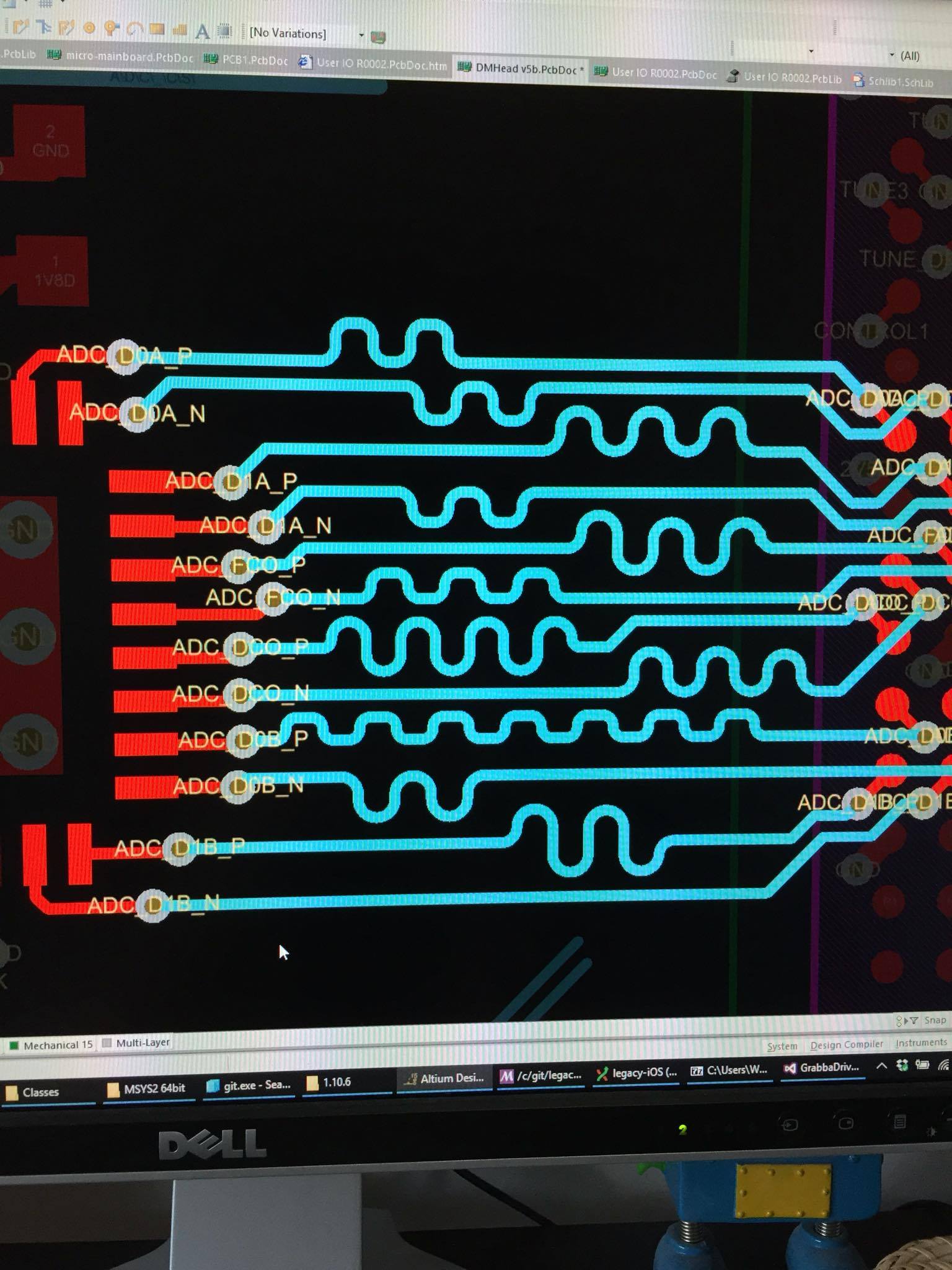
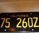
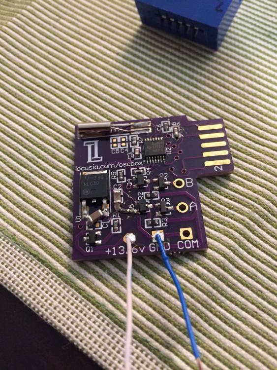
Epic thread dig i know... BUT i read this thread recently and then went about actually getting it done! Here is the long awaited modern replacement to the oscillator box for the 240Z rally clock. The clock has exactly the same movement as the stock setup. This circuit completely replaces your old oscillator box and is driven by a super accurate microprocessor, instead of a tuning fork. We have a full working example after reverse engineering my own rally clock. It now keeps time more precisely than the factory unit and will be very reliable, with no moving components. We have also located a plug that will be compatible with the OEM harness for people wanting a plug in solution. You can see from the pictures that you can actually mount this PCB inside the clock it is so small. If you are interested, we are happy to supply just the circuit or an installed board depending on what you want. If you want a metal box from jaycar we can do that, or post us your original oscillator box and we can convert it. Let me know what you want! First run will be about 10 units so get in quick! PCB cost is $99AUD each which is 1/4 of the price of the actual oscillator box which may not work! https://youtu.be/FXkWDCBmsII https://youtu.be/hwJEogI84pw

.png.ae0f62fbefb2e0eff4899bfd9341b9ba.png)
 1 point


.jpg.8f1b8d28a2acd49ca827ea700a65d3f3.jpg)