Leaderboard
-

Captain Obvious
Free Member2Points9,843Posts -

zKars
 Subscriber
 1Points3,747Posts
 -

torynich
Free Member1Points39Posts -

Mike B
Free Member1Points2,195Posts
Popular Content
Showing content with the highest reputation on 02/03/2018 in Posts
-
2 pointsThe aluminum housing of the antenna assembly should be electrically grounded to the body. And the extendable antenna (mast) portion must be electrically isolated from the "ground" of the body while being connected to the center prong on the co-ax cable on the interior of the car. It's been so long since I've been inside one of those things that I don't remember the brass finger things, but if they slide along the mast, they're probably there to help insure electrical connection.2 points
-
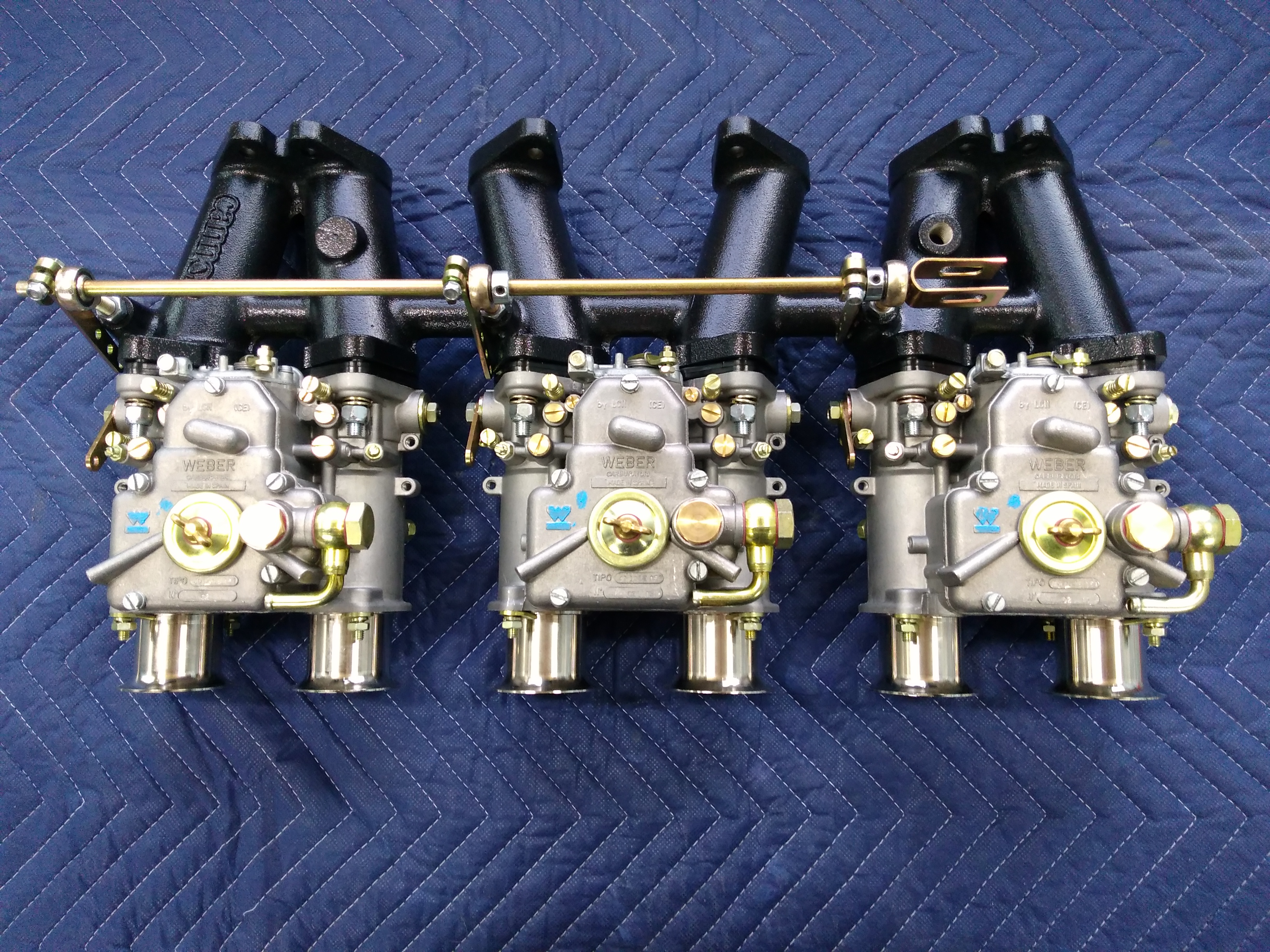
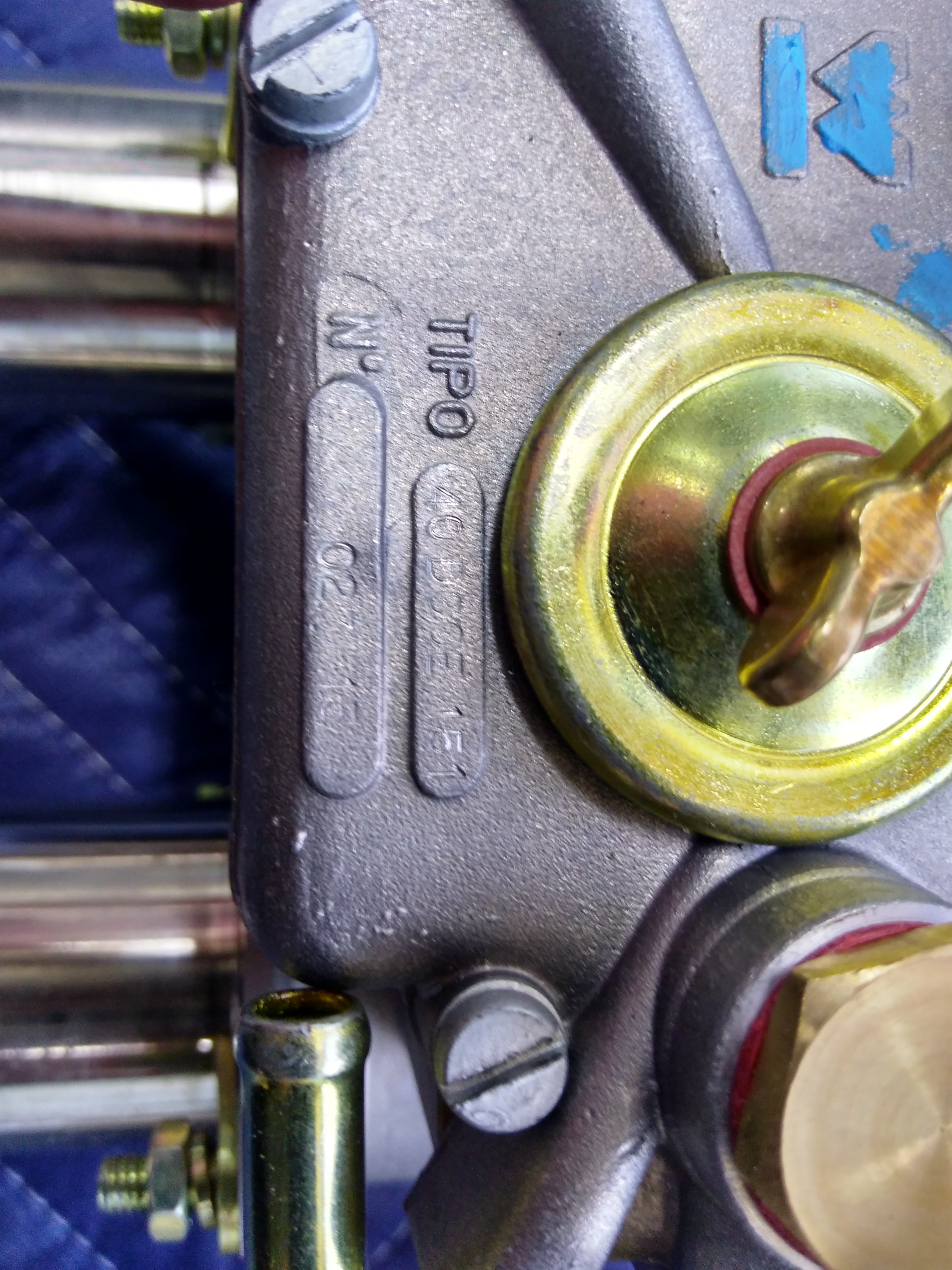
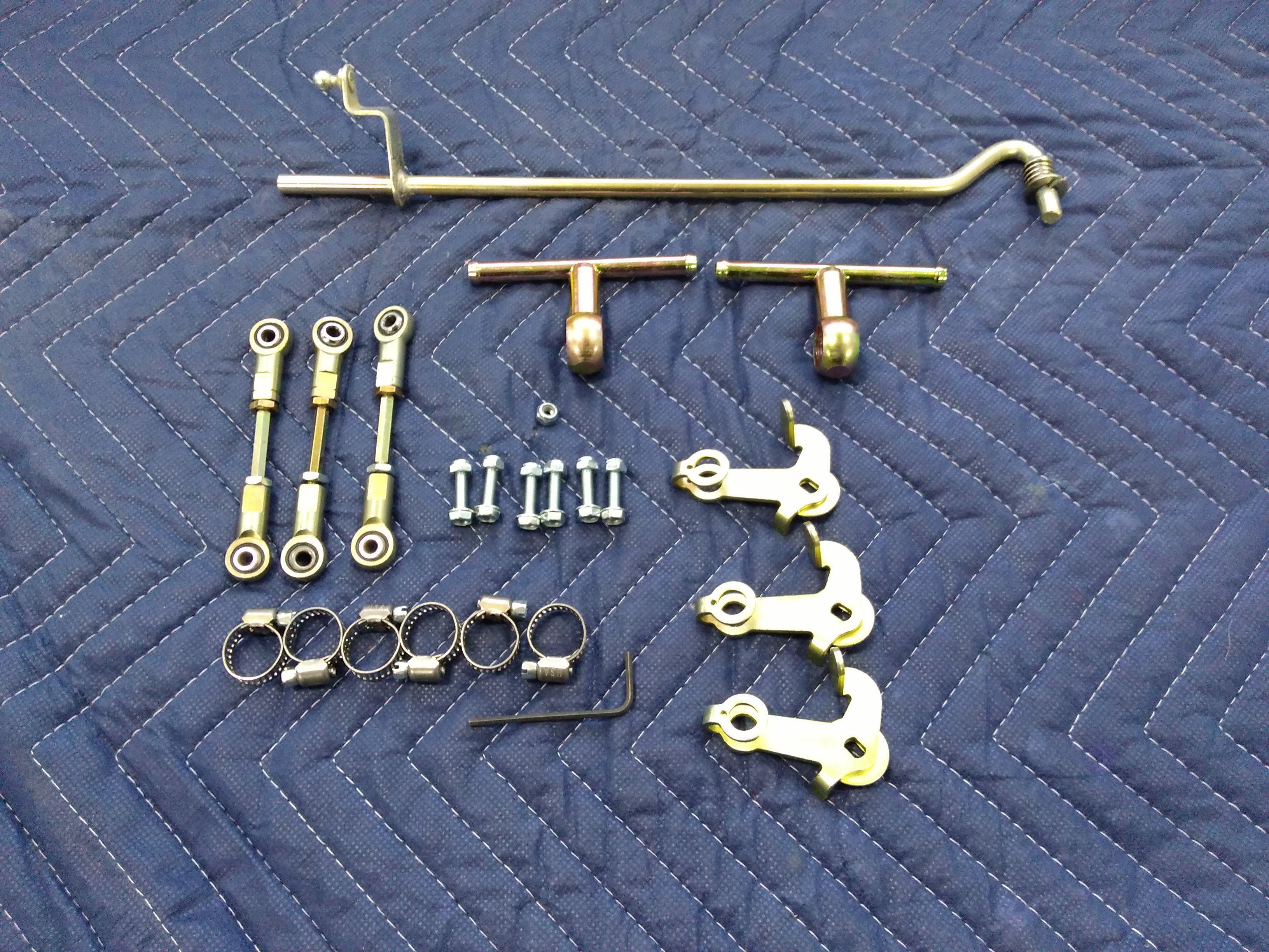
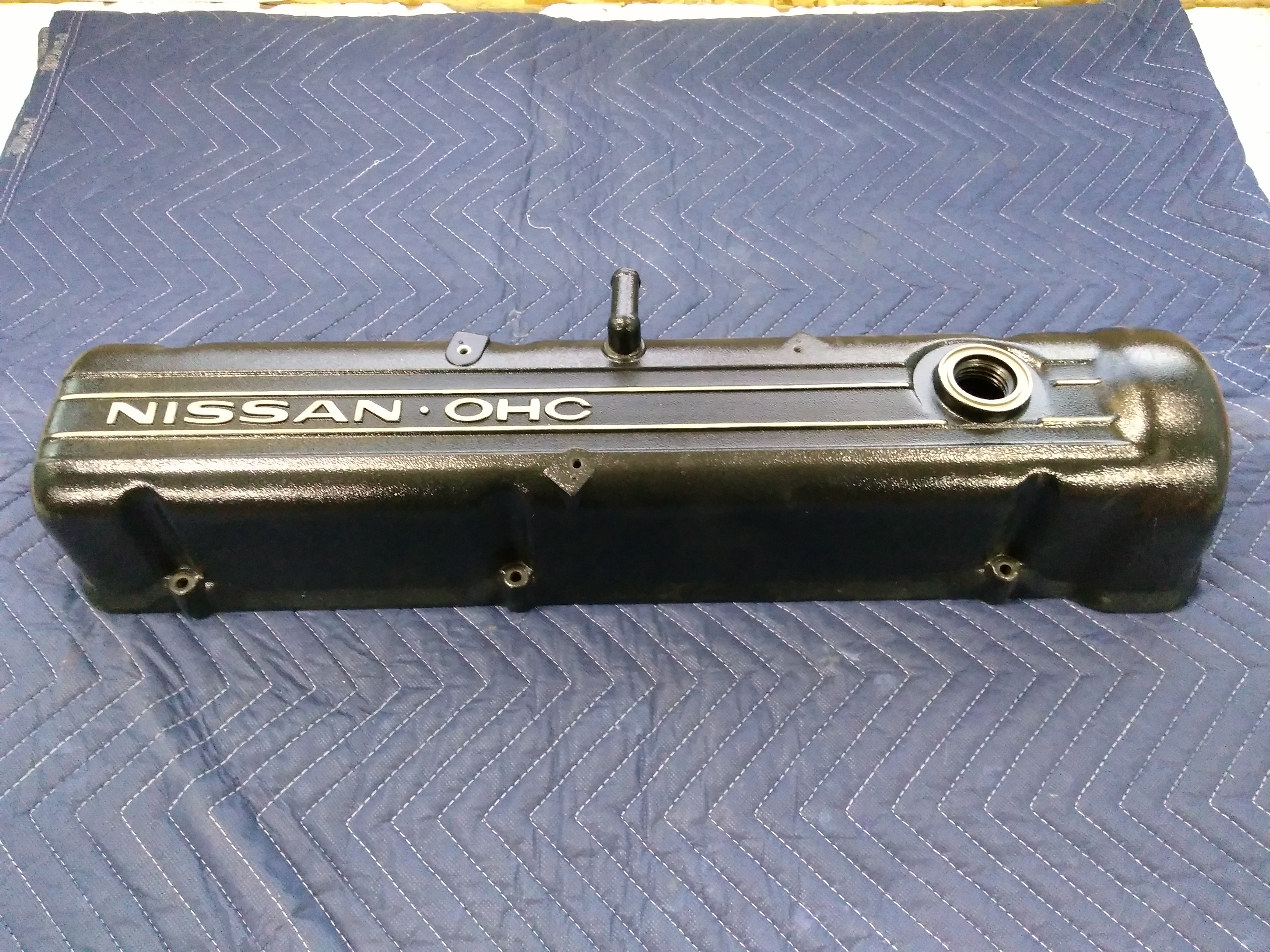
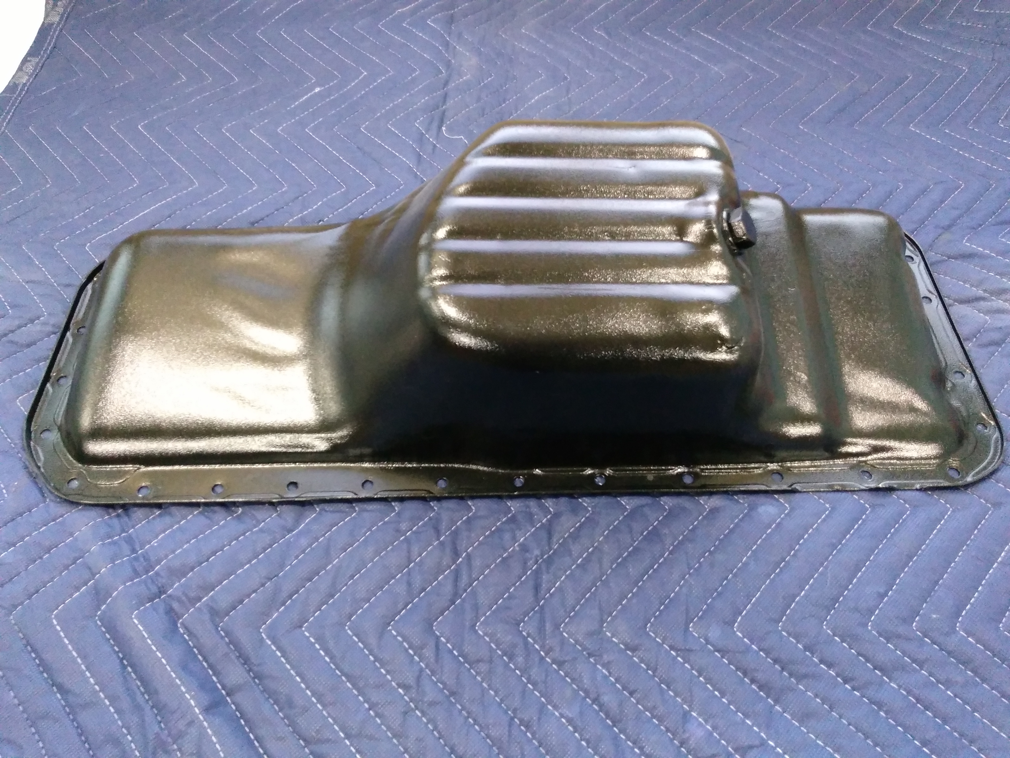
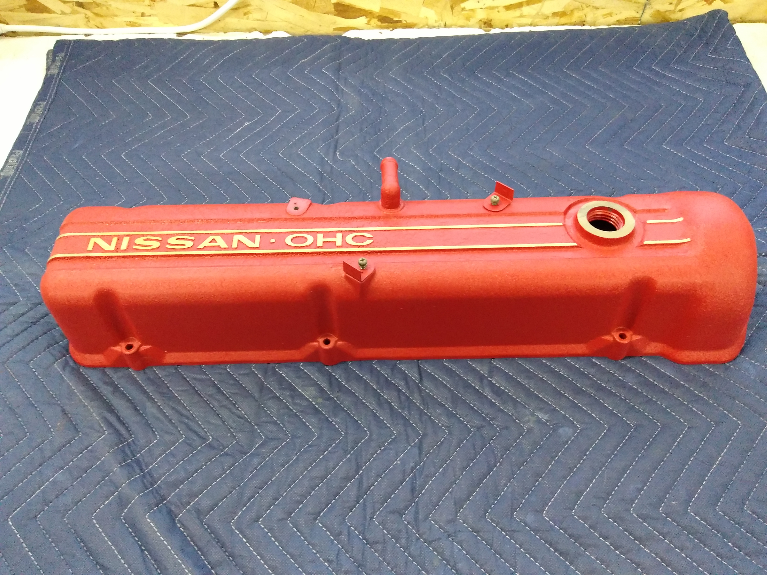
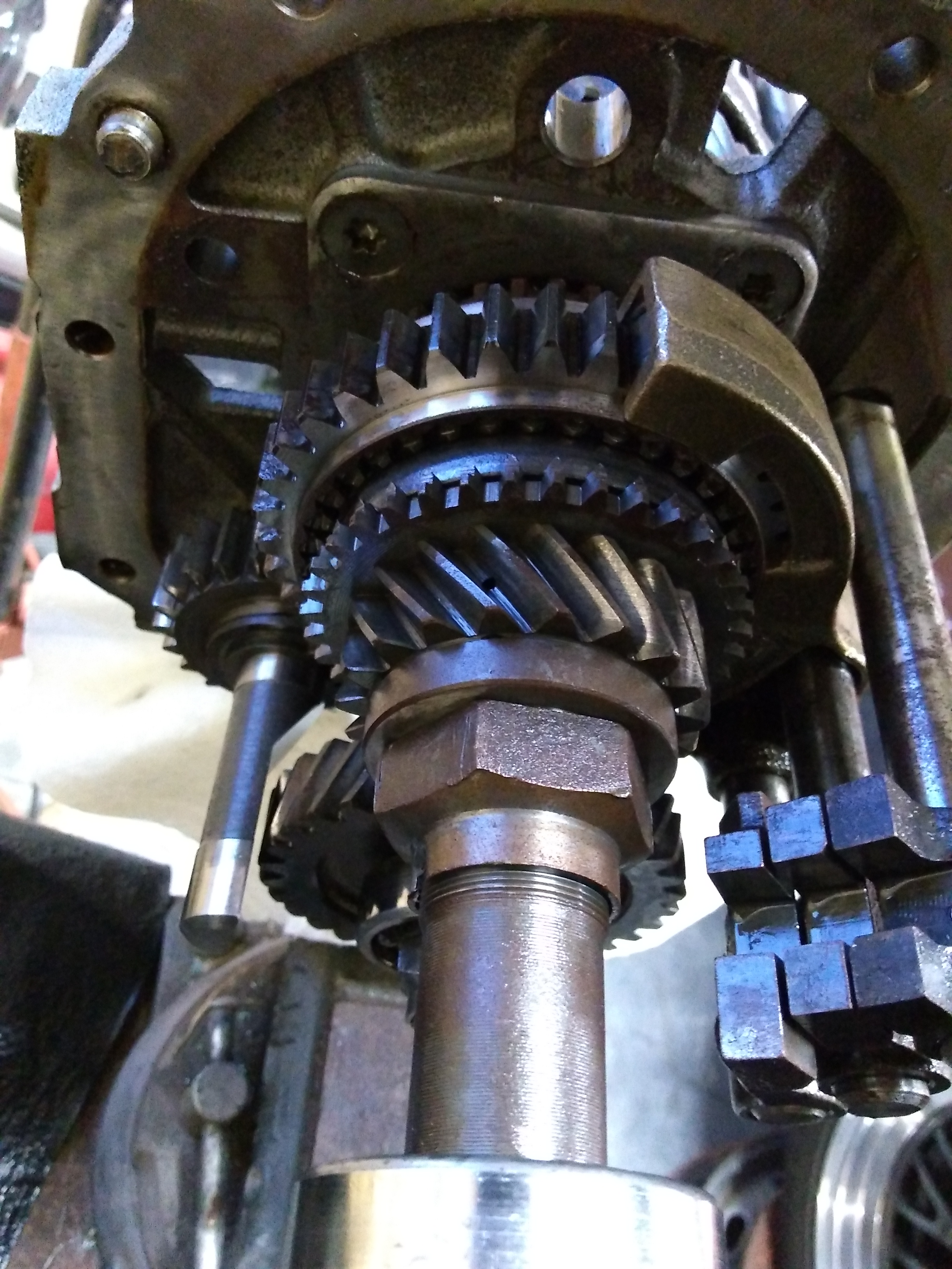
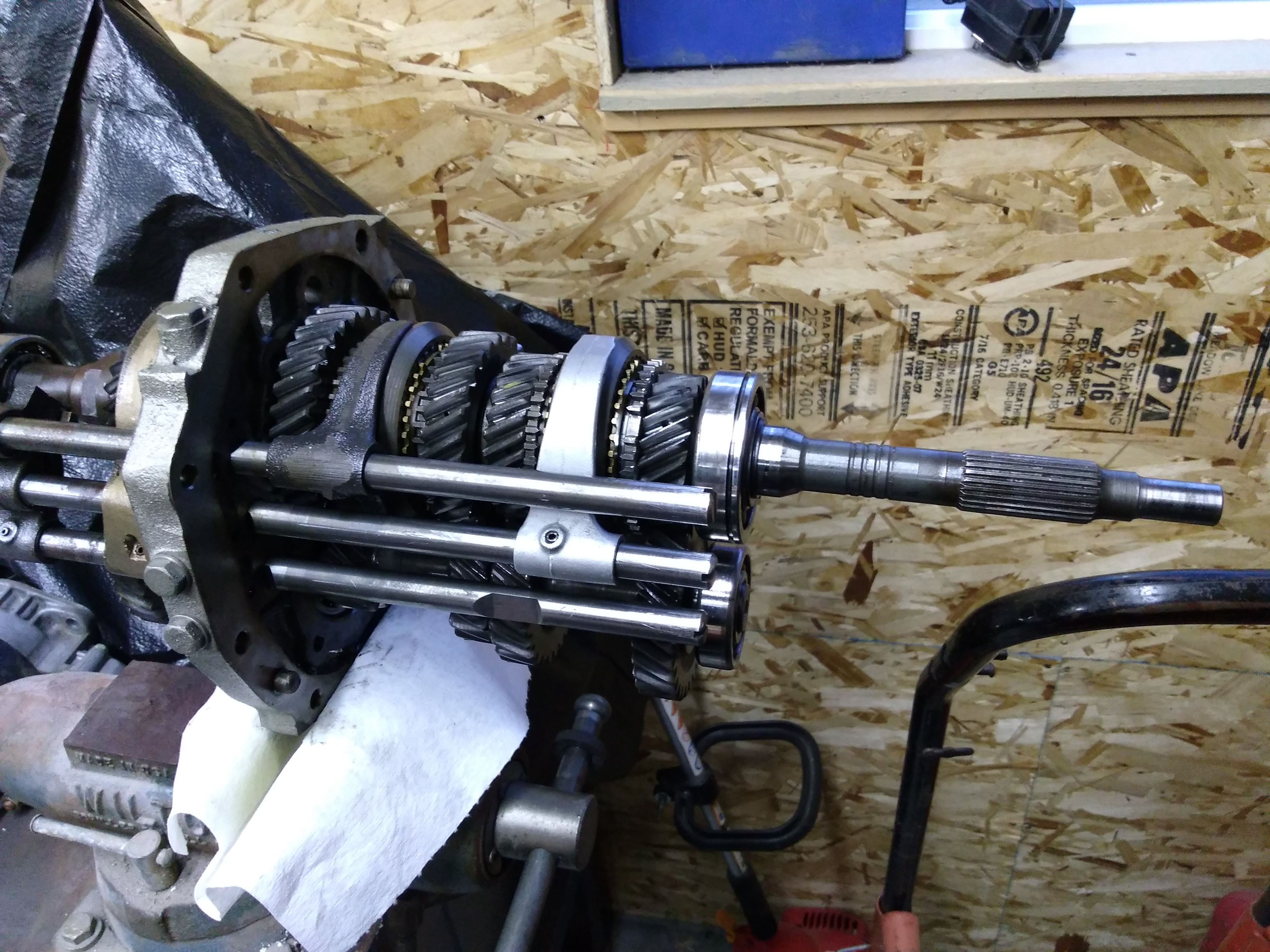
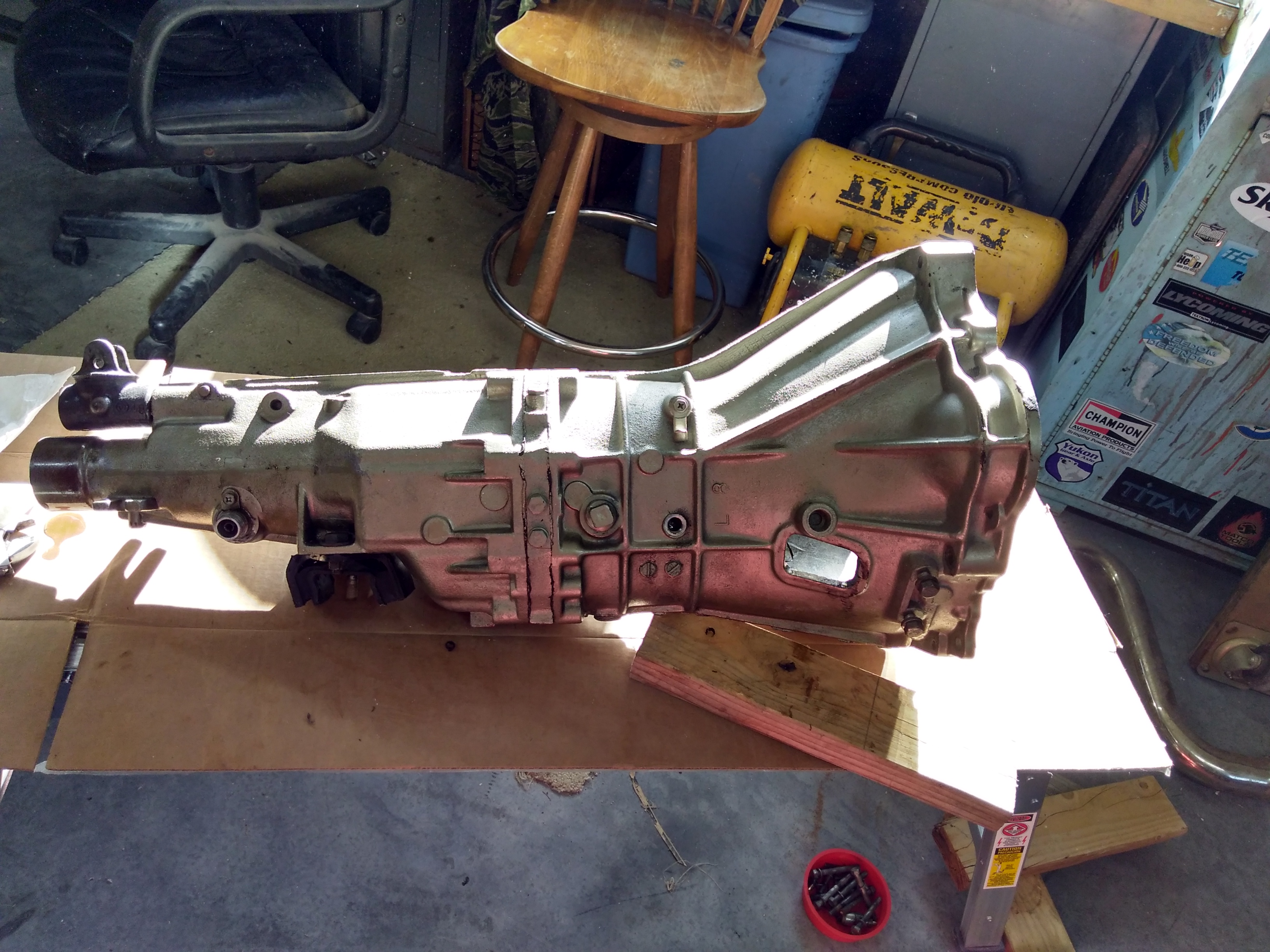
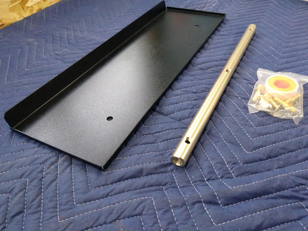
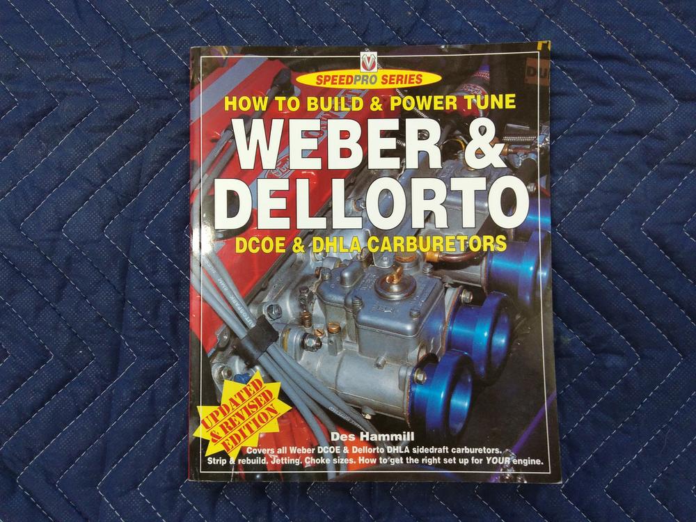
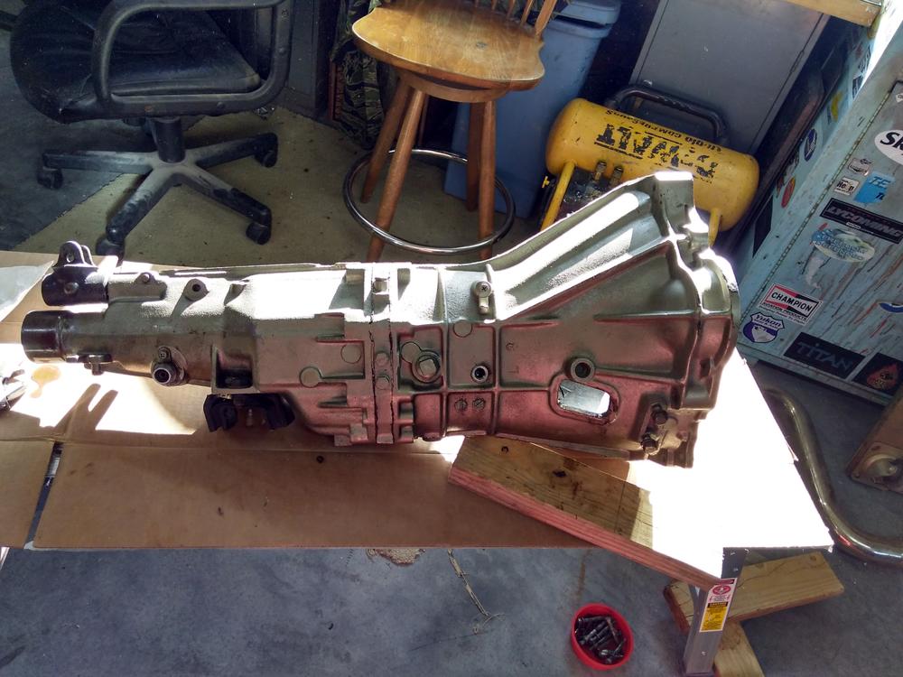
I accept crypto currency. I'm always open to trades. More pics upon request. Brand New 40dcoe 151's with black texture powder coated cannon intake, Datsun Spirit heat shield powder coated black texture and Datsun Spirit fuel delivery pipe gold anodized. "How to build and power tune Weber and Dellorto" book. $1700 shipped conus. One black texture powder coated valve cover, one black texture powder coated oil pan, and one red wrinkle powder coated valve cover. $50 each shipped conus Early 280 5-speed. $150 shipped conus. I bought this transmission a couple of years ago from a member of HybridZ as a recent overhaul. It sat for a couple of years in my garage before I got a chance to install it. After installation everything worked fine, shifted smooth, except 5th gear. It will go in to fifth gear just fine without the engine running, but won't go in to fifth while driving. I removed the transmission and disassembled it to inspect for damage but did not find anything obvious without further disassembly. I didn't want to disassemble it further so I decided to upgrade to an SX 5-speed. I used this front case for my new 5-speed so this one will come with a 4-speed front case that will need to be machined to accept the reverse light switch in the correct location. I will throw in an early 4-speed input shaft assembly also so you can make a frankentranny if so desired (I was planning on doing this to go with my 3.36 rear gears instead of swapping out the rear end).


 1 point
 -
 1 pointHar har har, glad I asked. I guess I'll store it next to my Flux Capacitor when I'm done with it1 point
 -
1 pointSounds to me like you acted correctly to do all you could to keep the damage to a minimum. None of this was your fault at all, instead it was a skillfully executed set of maneuvers that may have saved someone's life. If she u-turned in front of you, that puts the drivers door right in line with your rather large truck. What transpired from your quick reactions and commitment to making the best of a bad situation rather than closing your eyes and slamming on the brakes, is dang near heroic. I call that a pretty good day.1 point
-
 1 pointIn looking at the design of the antenna I believe that this is correct. The connection to the mast has to be through the housing of the mast and the "brass fingers" would serve that purpose, through the retainer nut to the brass threads which are isolated from the body of the antenna. The antenna cable is connected to the brass threads that the retainer nut attaches to. I am not 100% sure of this, but it makes since when you look at the design of the antenna.1 point
 -
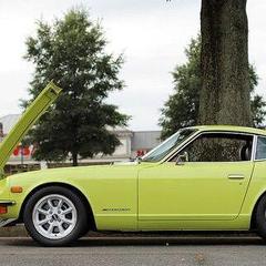 1 pointWow.....You’re really moving ahead. I don’t think anyone on this forum realizes how incredible this build is going to be Brandon. It’ll be in magazines for sure.....can’t wait to see a little Safari Gold color applied.....perfect blend of old and new, along with a beautiful new RB 26 NA. Charge on!1 point
 -
 1 pointThe Brass "fingers" must be installed in the finisher nut for a proper fit. There must be zero left over plastic from the old top in the finisher nut or on the brass "fingers". The lower lip on the new top is paper thin but it must be like this for the correct fit.1 point
 -
 And so begins a new adventure, guaranteed to frustrate yet entertain over the next few years...1 point
 -
 1 pointInteresting. I got an early electric 240Z antenna a couple years ago and it has the Hitachi Mark. Sent from my [device_name] using http://Classic Zcar Club mobile1 point
 -
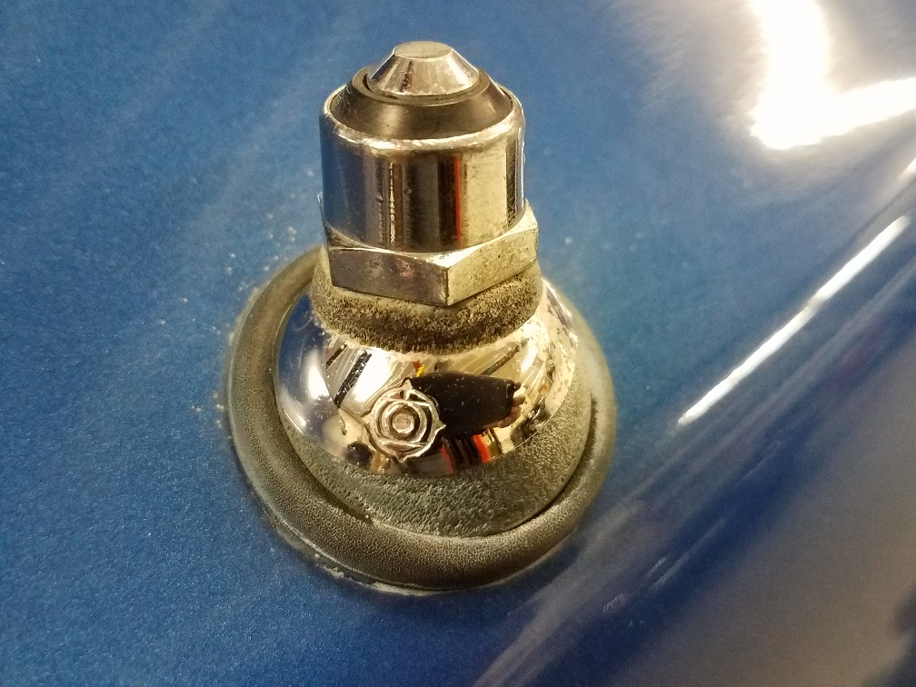
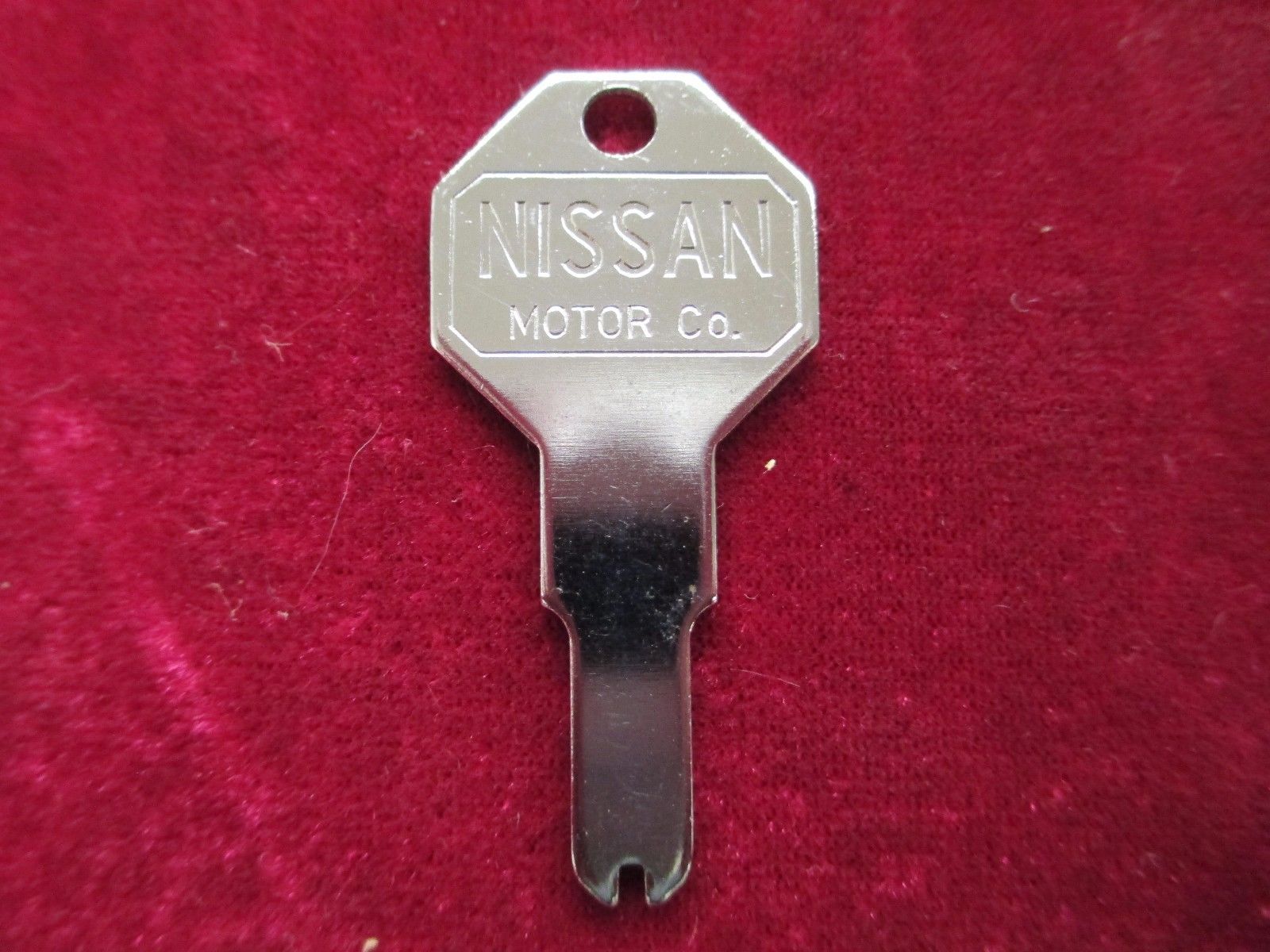
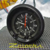
1 pointHi Kats, This is a picture of the manual antenna showing the emblem on the round metal piece and another photo of the original Nissan key. -Mike

 1 point
 -
 Hey d3c0y, If you measured the feed through to ground and it was shorted then one can surmise that the capacitor internal to the feed through was shorted. However, I have not seen one that was shorted , but I always measure the case to feed through just to make sure. One question I still have is what is the capacitance of this feed through and what noise is trying to be eliminated, frequency? I'm not sure this feed through is relevant to the OEM ckt bd as there are several internal caps on the subsequent ckt bd(s) that take care of this potential problem. The OEM ckt boards have 3 revisions , C_D_E over the years, and I have tracked each trying to understand what they , JECO, was trying to do. Not sure if this feed through was very useful after the first revision other that a convenient place to connect the power wire (red) to the (green) motor power. Not sure if it's relevant to your ckt bd , but what I have observed on the OEM bd is that there is only an input resistor for current limiting and a Zener pull down to clam the voltage. In my opinion if Jeco was concerned with noise then why didn't they address this in a ckt up front and the voltage, full wave rectifier. Subsequent clock manufactures , Kanto Seiki and Citizens both have DC filtering on their clocks. One of my pet peeves is that Datsun protects the clock on a 10 amp fuse? Most clocks only require 15- 20 mili amps so why put it on a 10 AMP ckt!!! By the time the fuse blows the clock will be a puddle of metal. .The only protection in most clocks is a simple resistor that has to melt before it protects the ckt. I've seen this in the std clocks, calendar and the 2-knob rally clocks. The clocks in my cars are all fused on 1/4 amp fuses and that is still high .Not that there is a problem, but come on 10 amps! All the 240 and 280 clocks are fused on 10 amps by Datsun . Anyway. enough of my ranting. Hope this was of interest to someone. Ron (Zclocks)1 point
 -
 The Tokico Illumina shocks typically used on a 240Z application are: BZ3015 - 240Z front. BZ3016 - 240Z rear (which is the BZ3015 shock with a 2" spacer attached at the bottom). BZ3099 - Toyota MR2 rear. For a nearly stock ride height car (stock length struts) the BZ3015 and BZ3016s are fine. For a car lowered 2" or more the struts need to be shortened and the BZ3099 is used on front and the BZ3015 is used in the rear struts. Per the Tokico engineers and my experience, the Tokico Illumina rebound control is limited to about 250 lb. in. spring rates. Anything over those rates and the rebound valving tends to go open and not control the springs as well as it should. Another negative for racing purposes is that the Tokico Illumina adjustment affects both compression and rebound. That is typical of a street performance shock where drivers want to feel things get stiffer without resorting to stiffer springs. Its not as good for a racer who is looking for compliance in compression because the racer is already running stiff springs. The combination of stiff springs and stiff compression damping makes for a car that doesn't handle as well as it should. IMHO, Illuminas are fine for a street car with spring rates up to about 200-225 lb. in. (I run a set on my street 240Z) but once you go beyond those rates a properly valved Bilstein, Koni single adjustable, or something more exotic will make the car handle much better.1 point