Leaderboard
-

qz16
Free Member7Points147Posts -

grannyknot
Free Member6Points5,158Posts -

calvinhg
Free Member2Points149Posts -

Patcon
 Subscriber
 2Points10,926Posts
Popular Content
Showing content with the highest reputation on 12/01/2018 in all areas
-
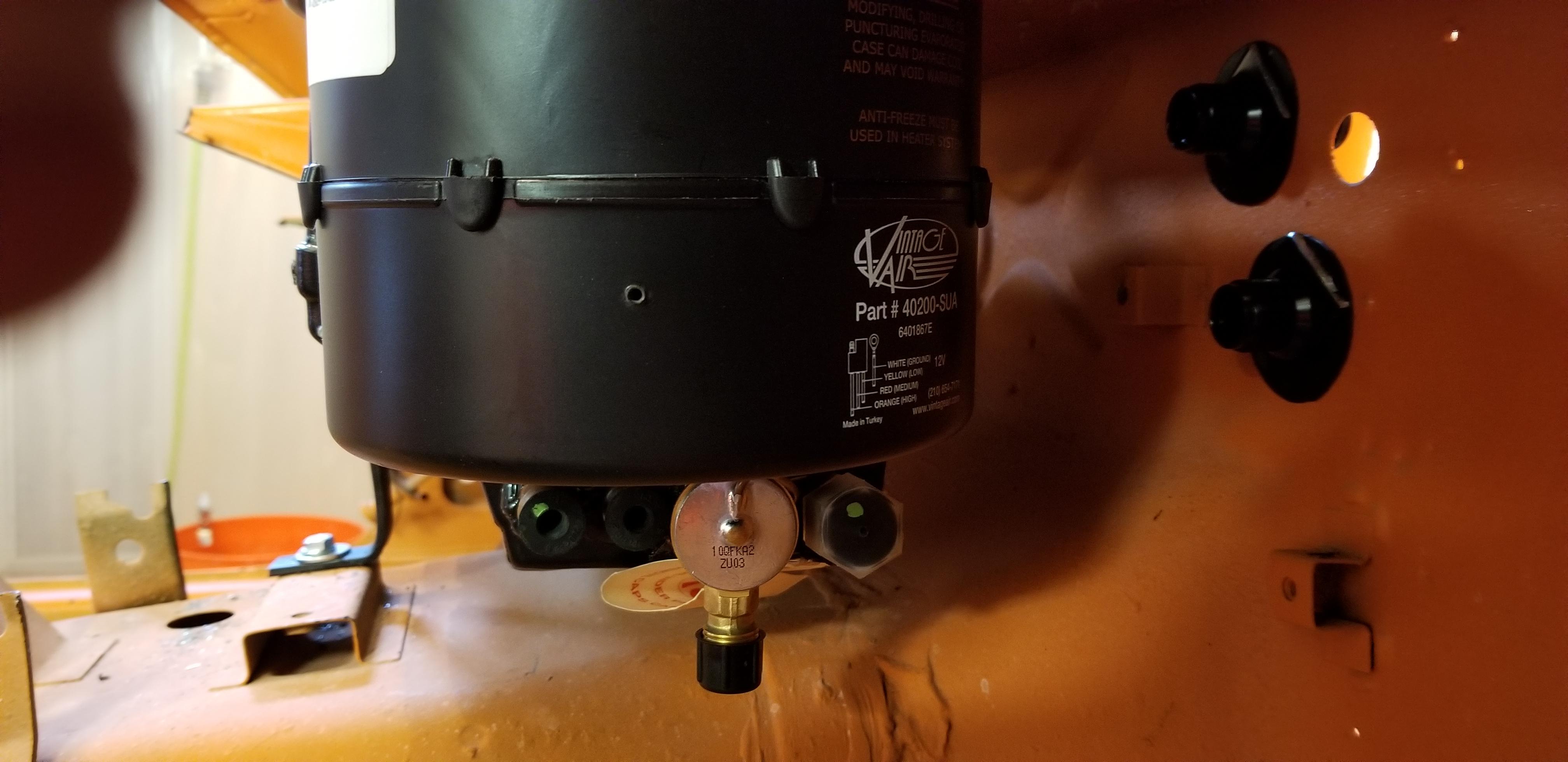
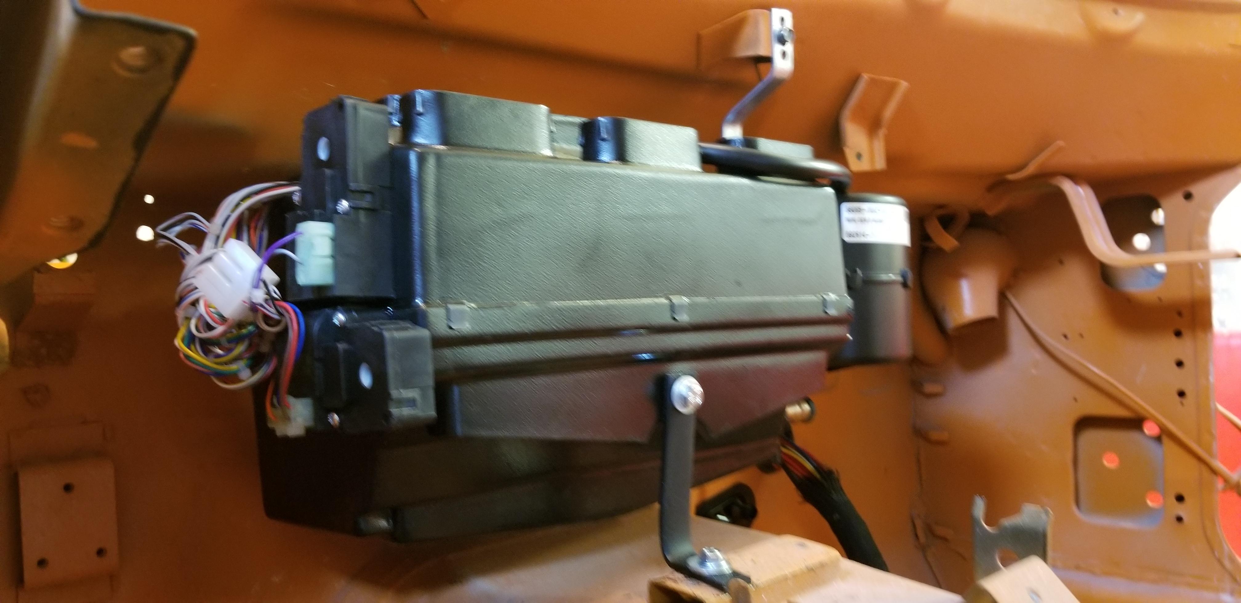
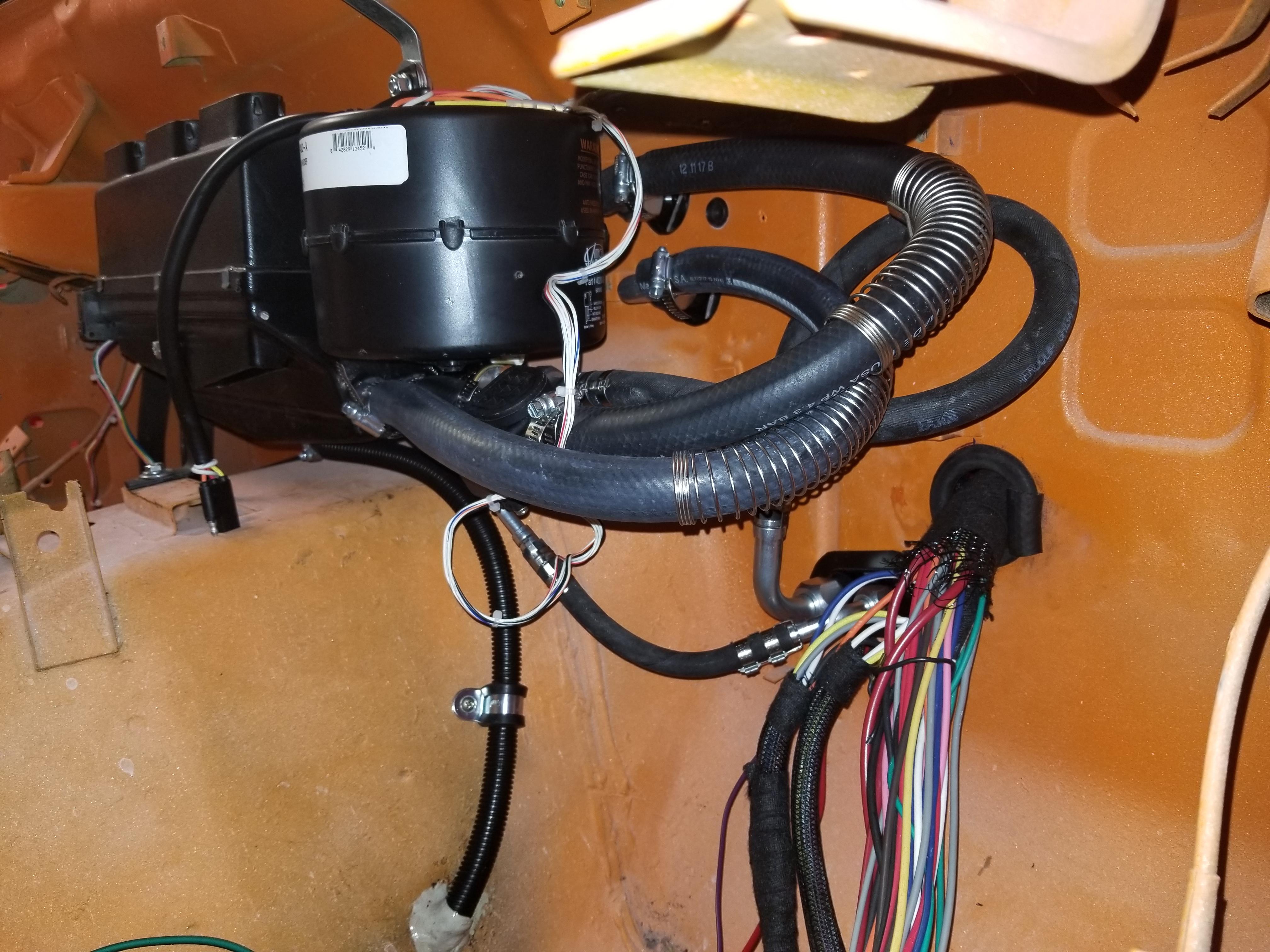
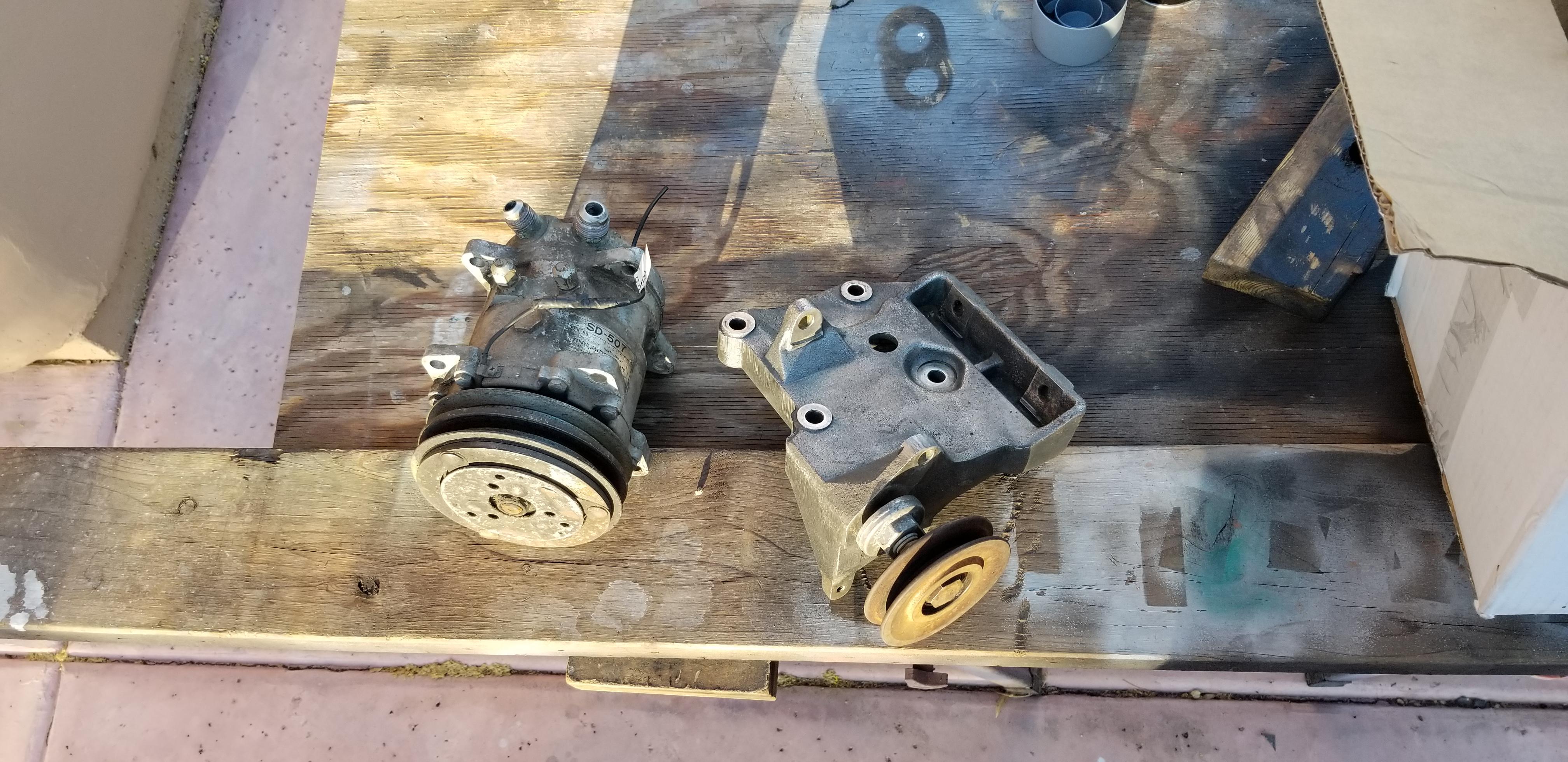
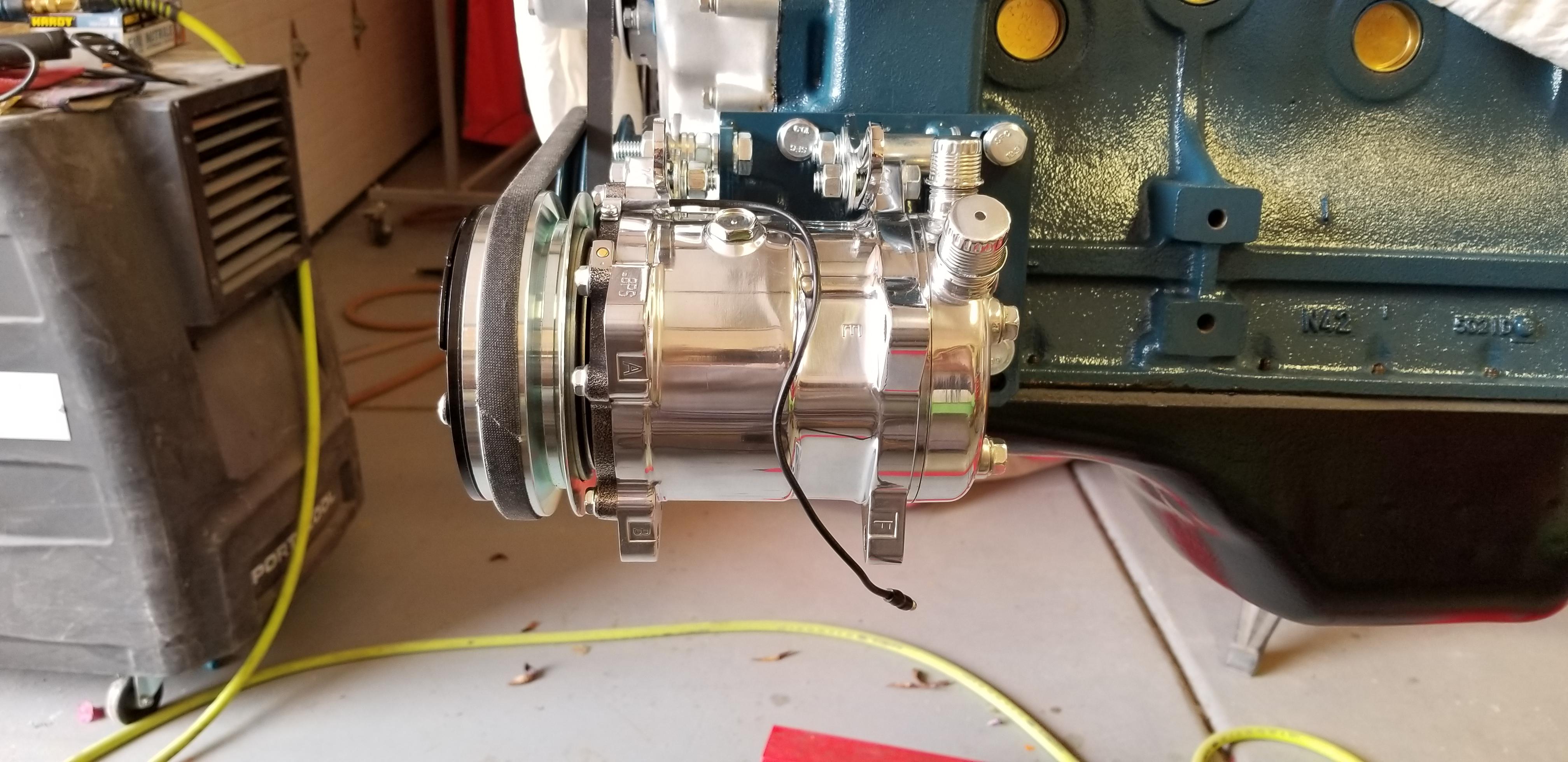
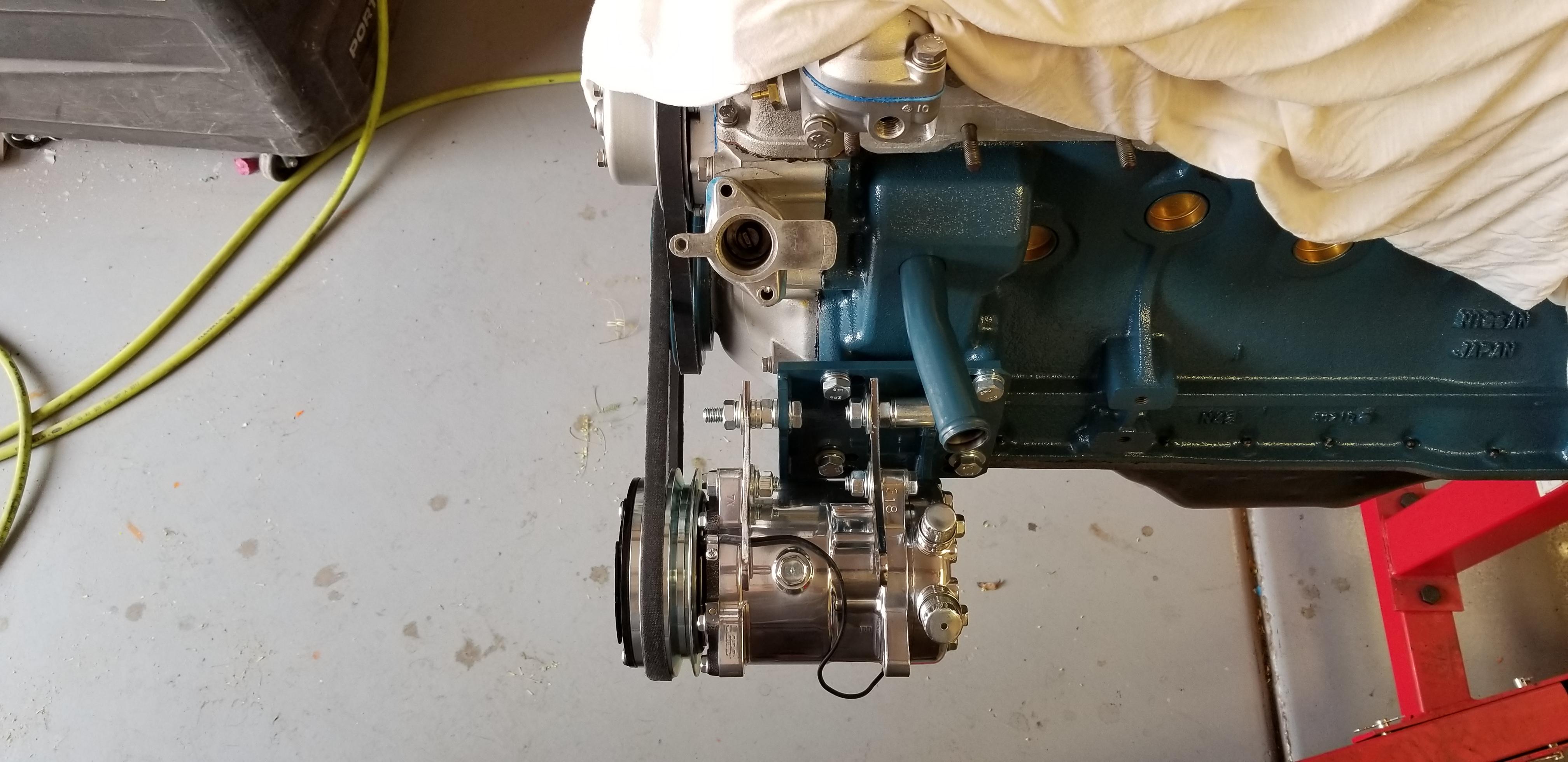
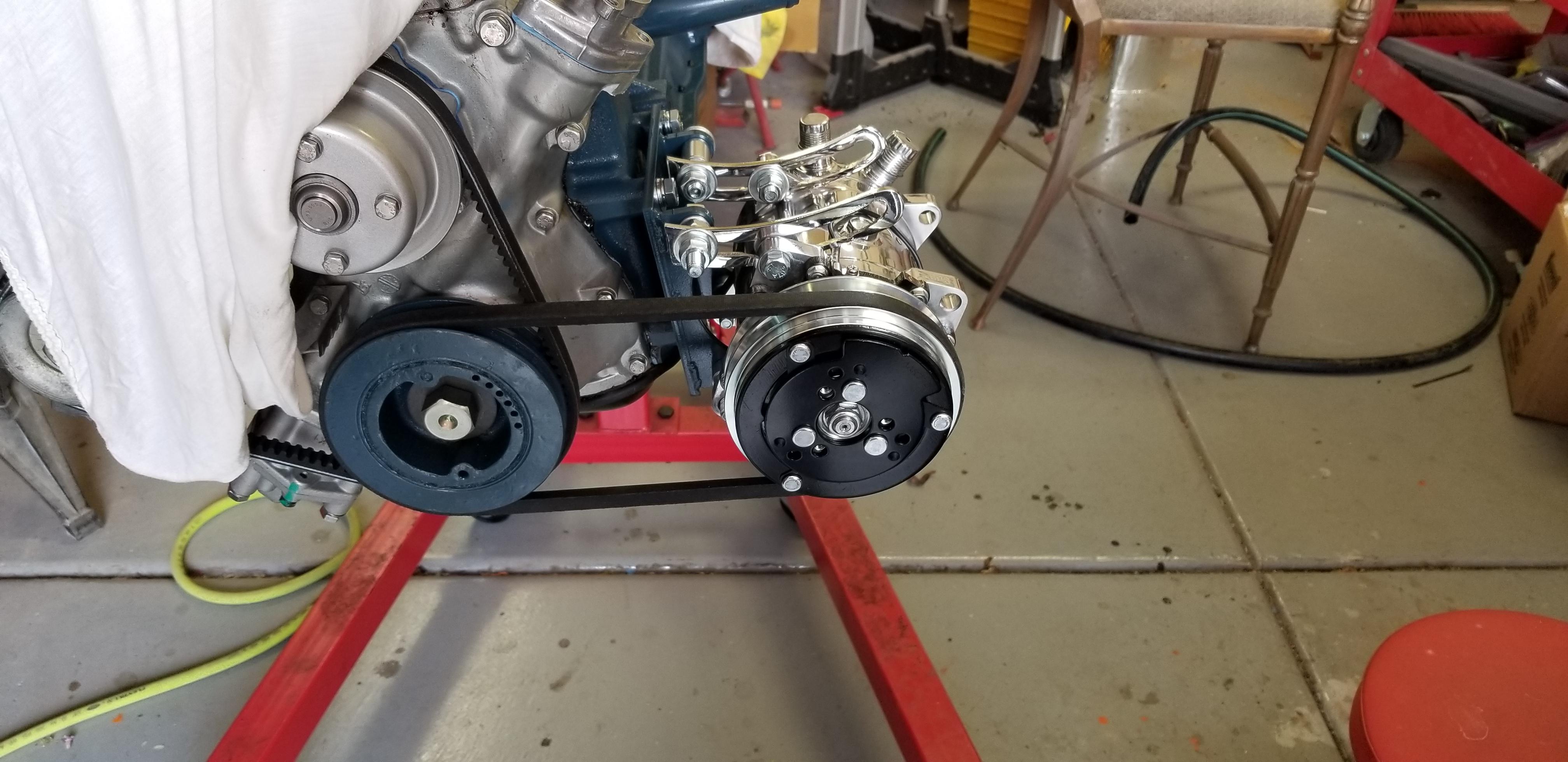
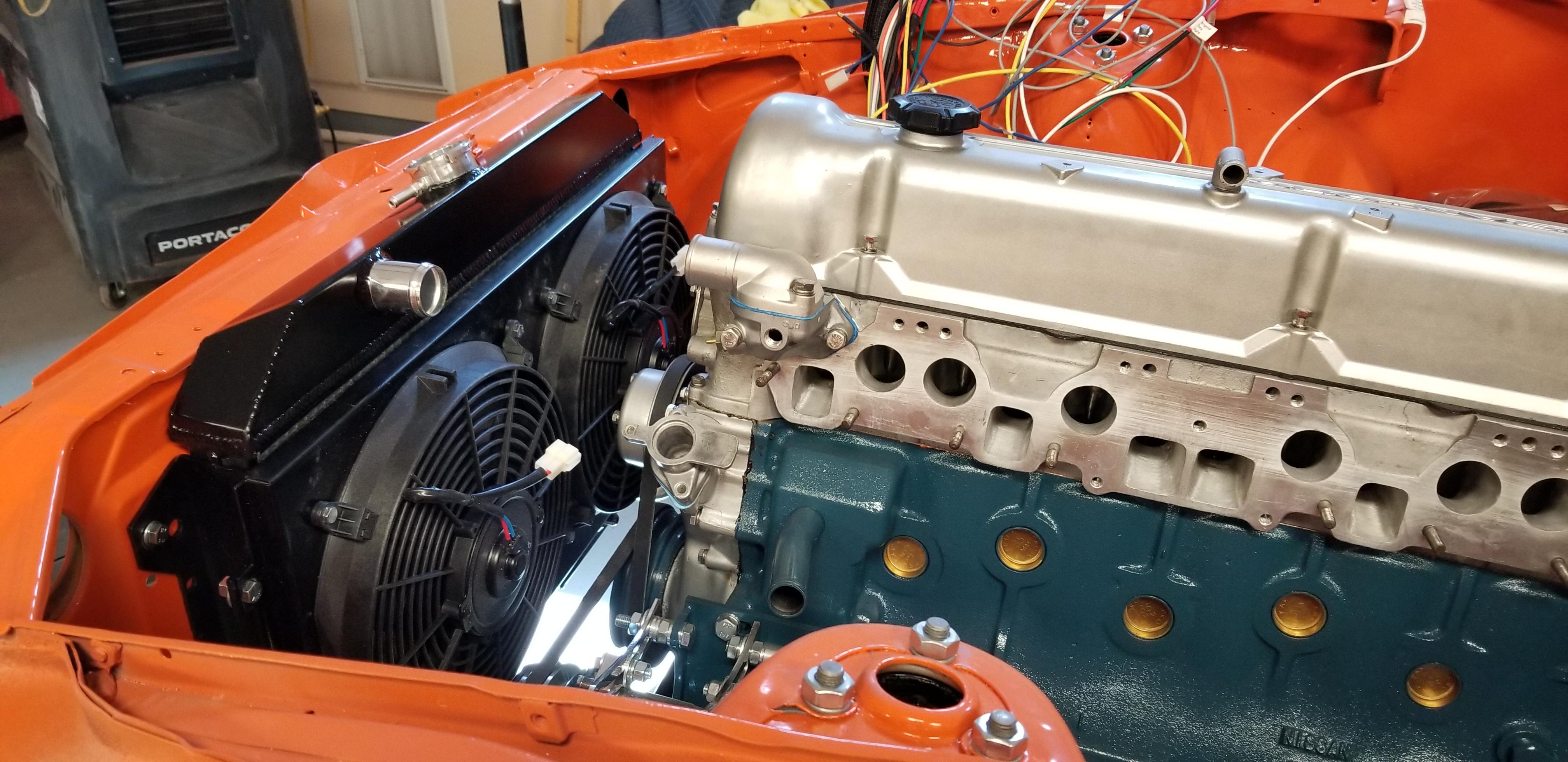
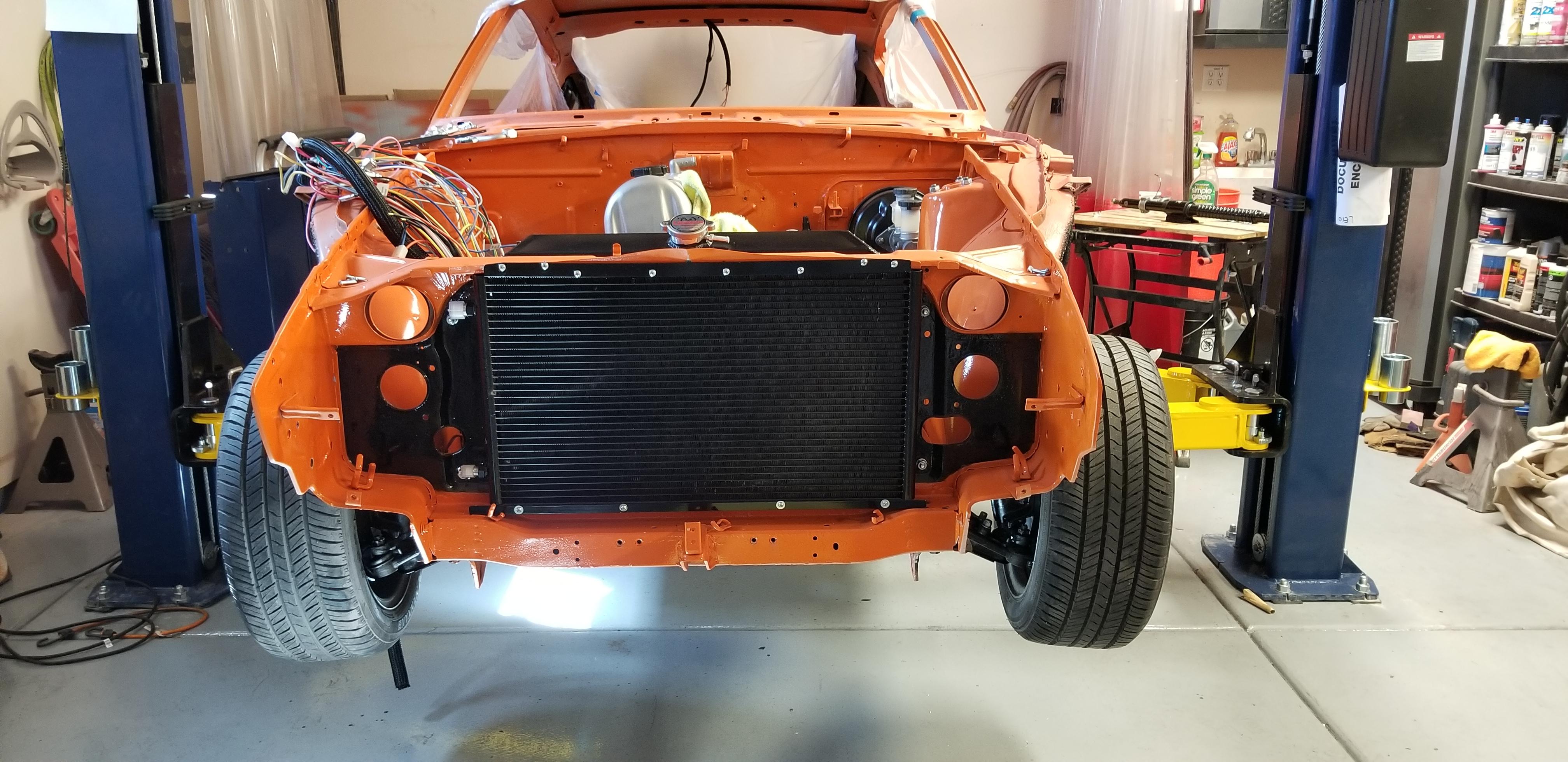
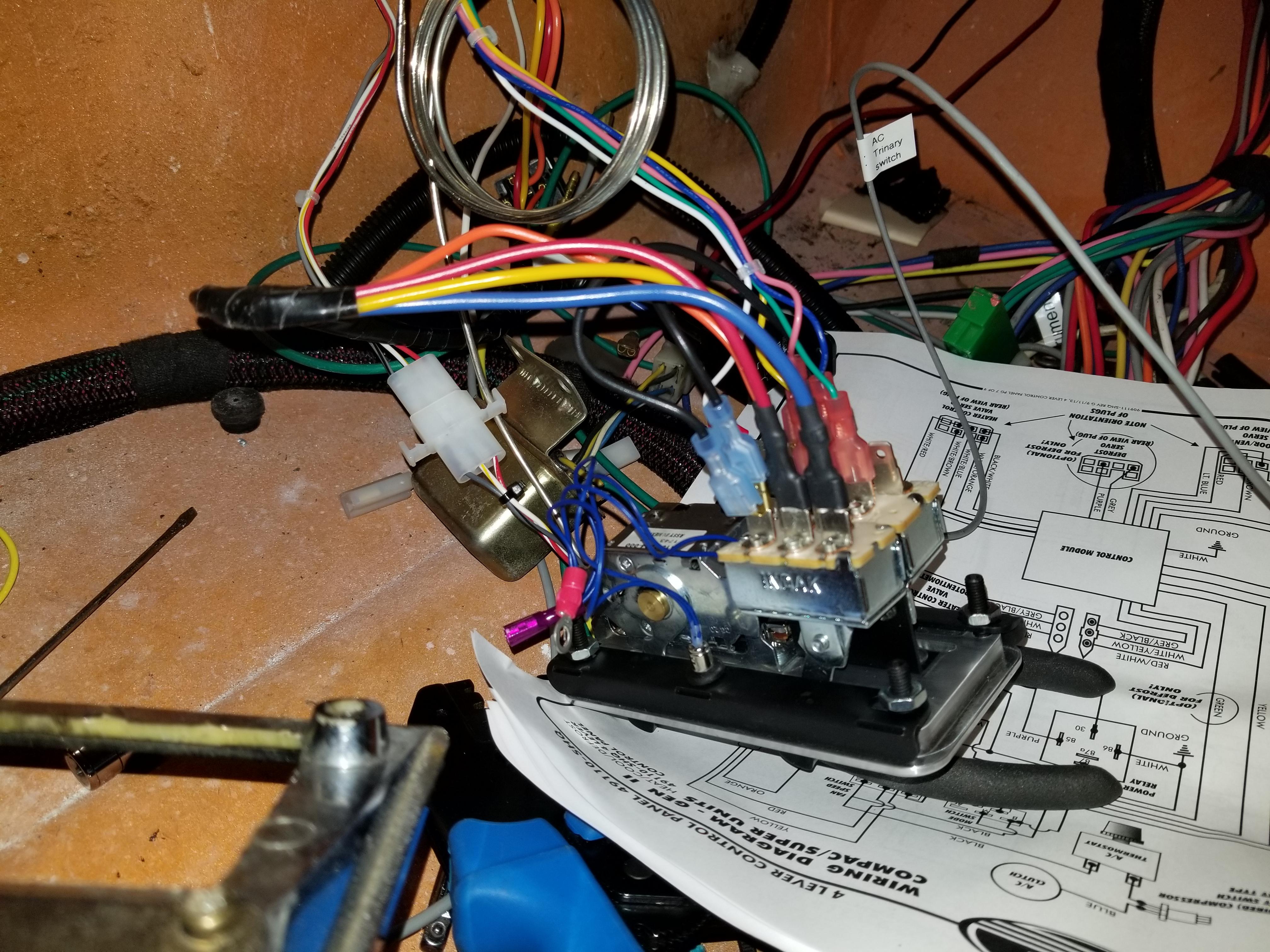
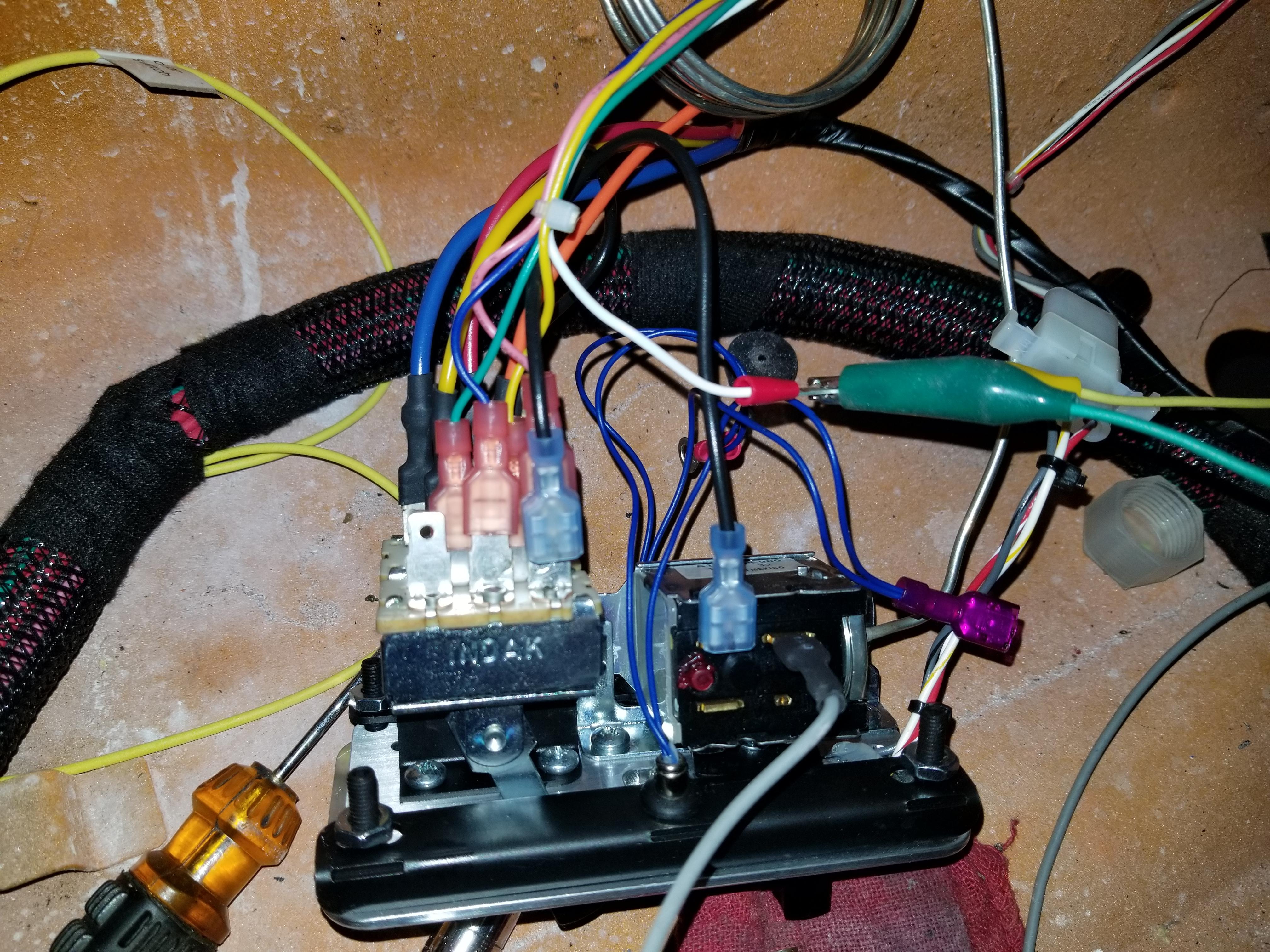
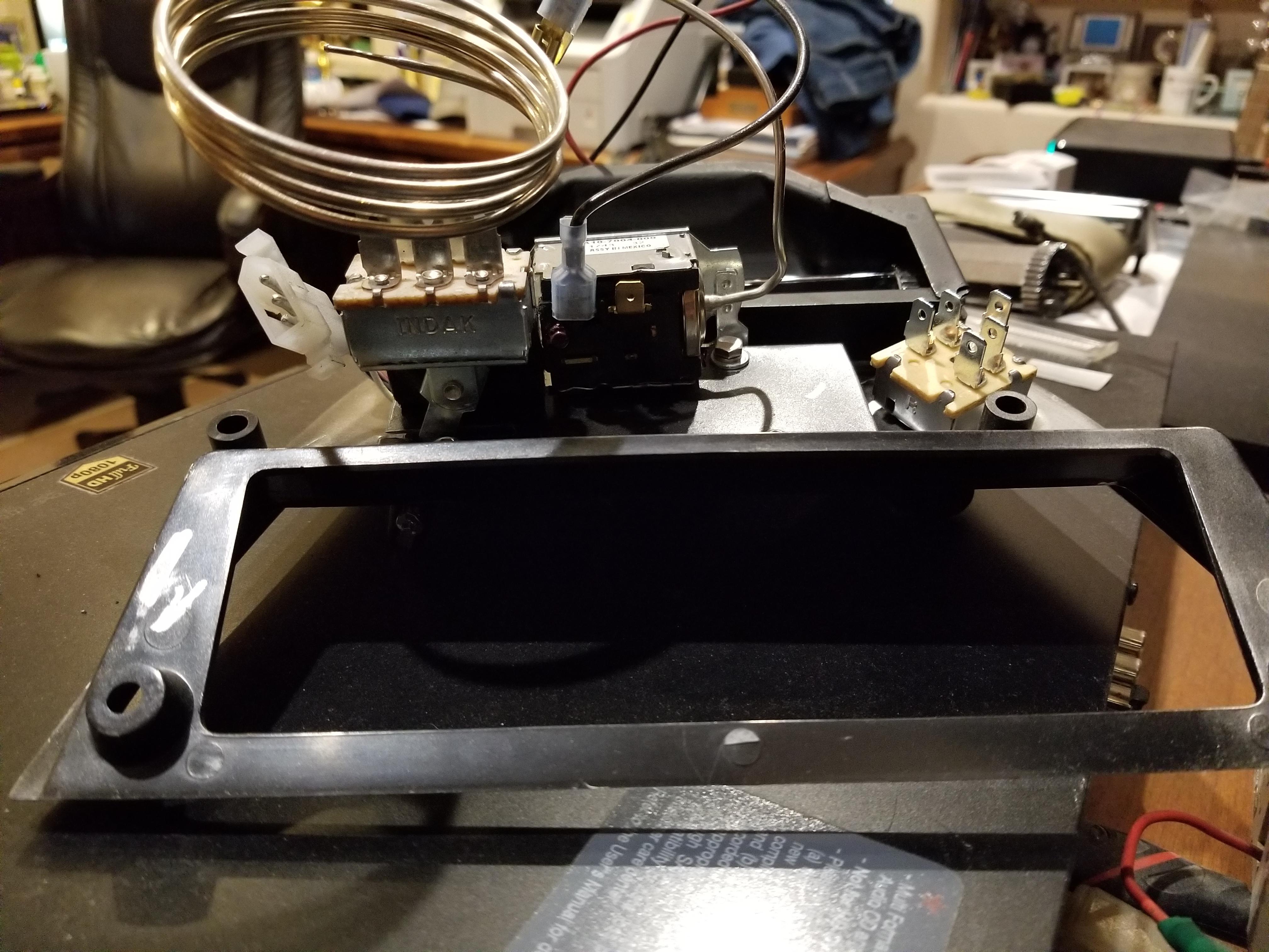
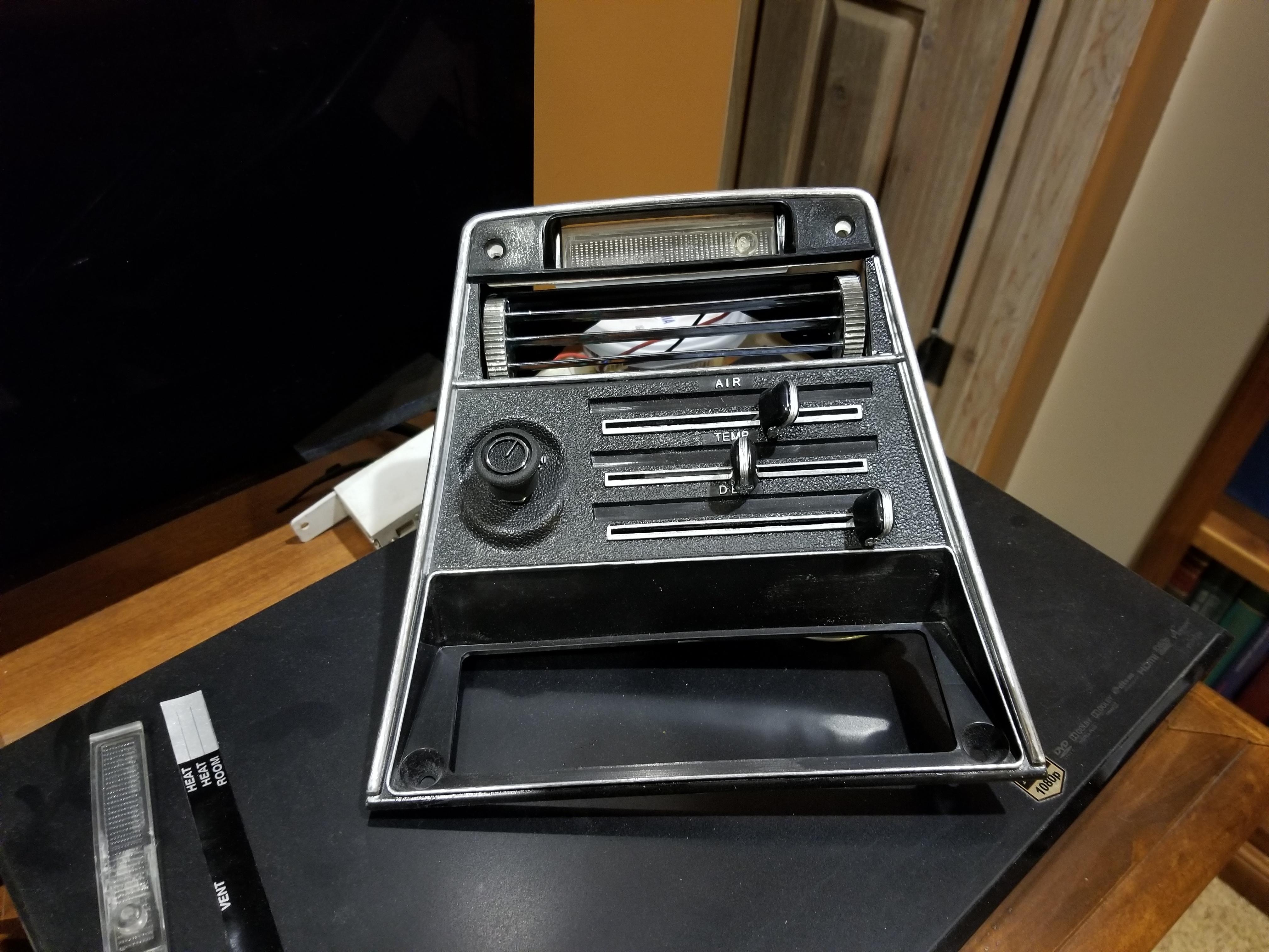
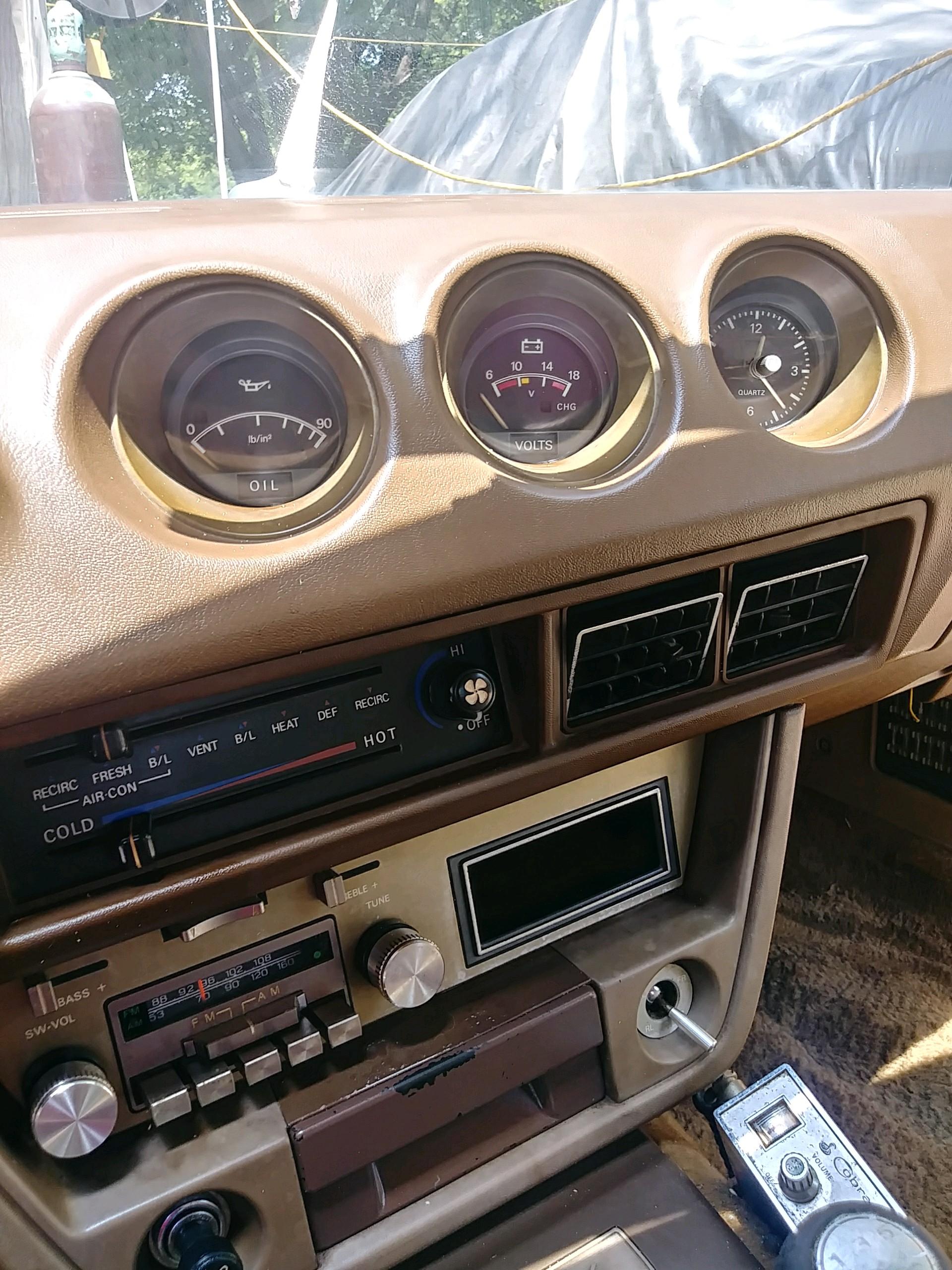
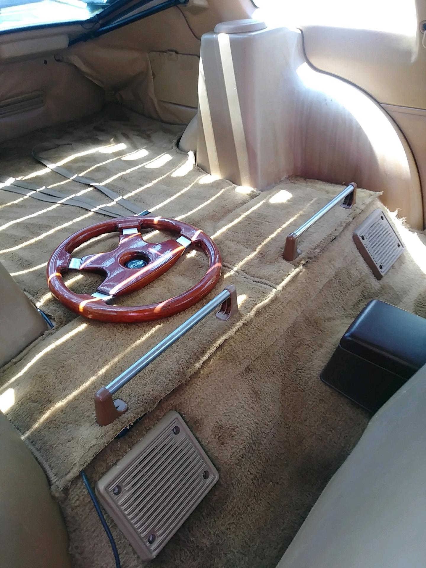
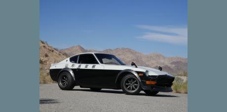
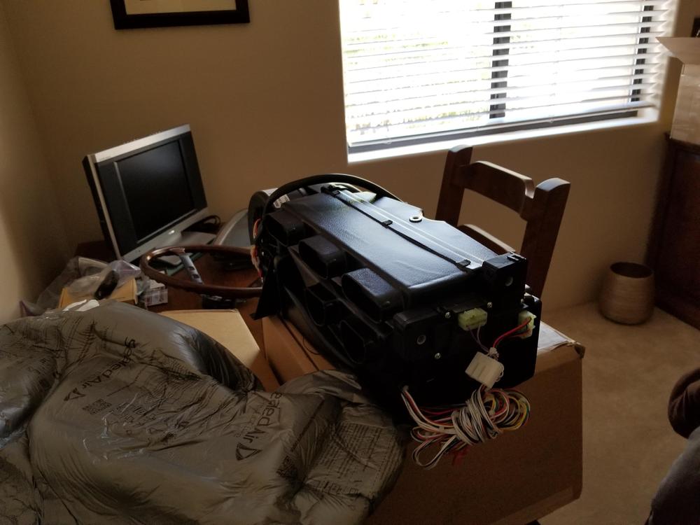
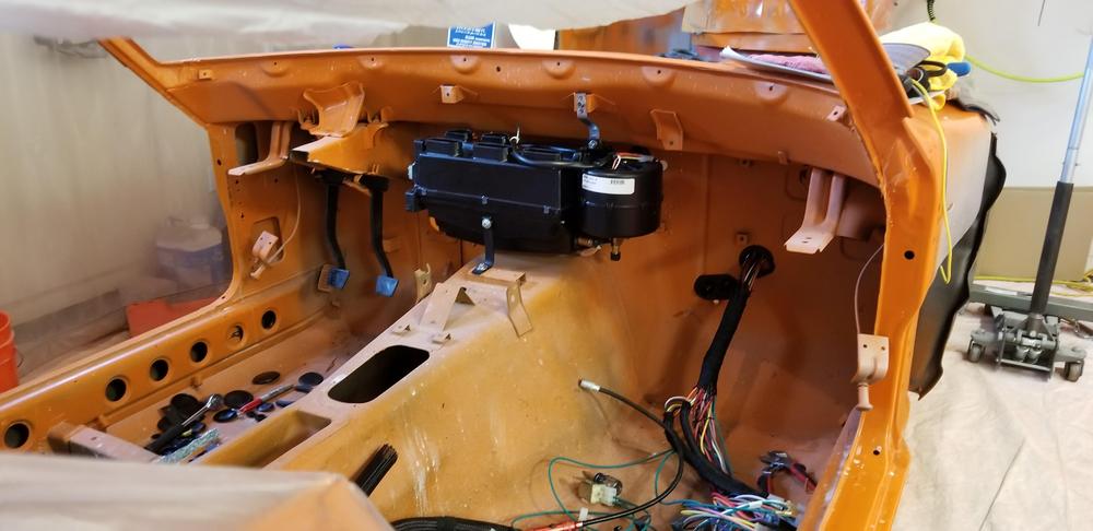
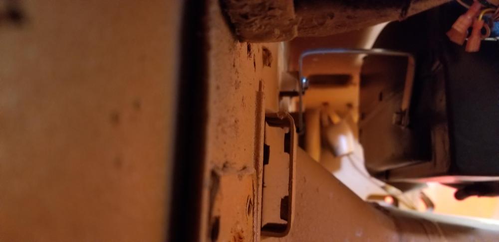
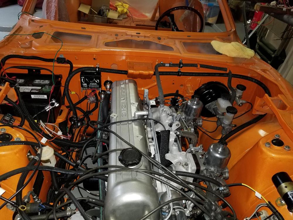
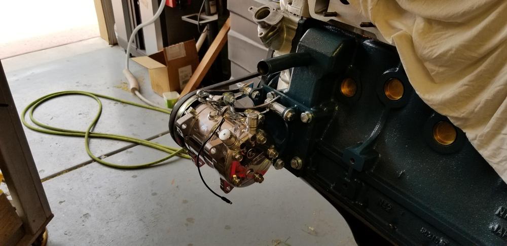
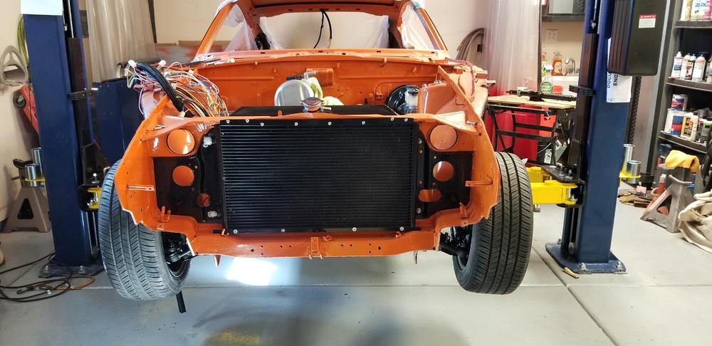
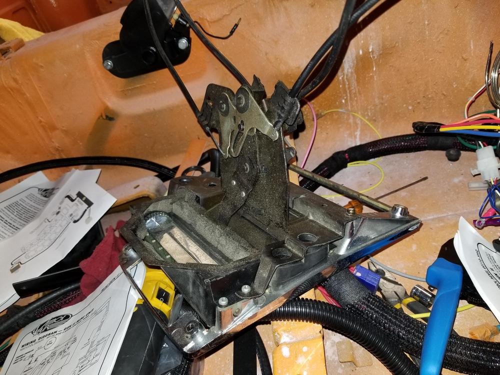
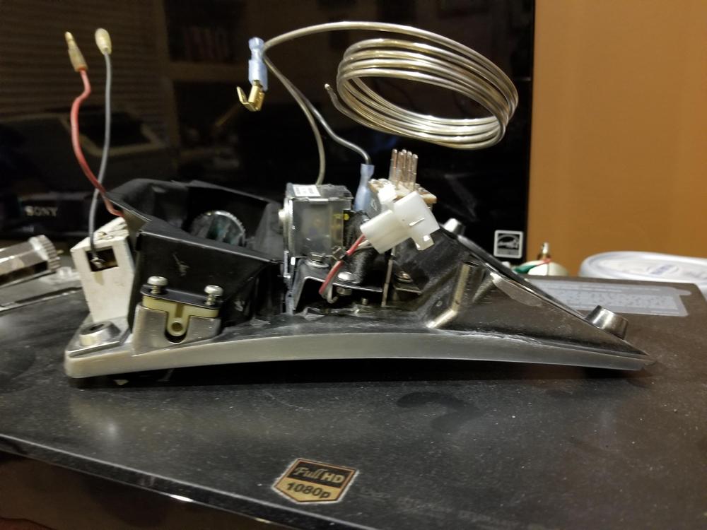
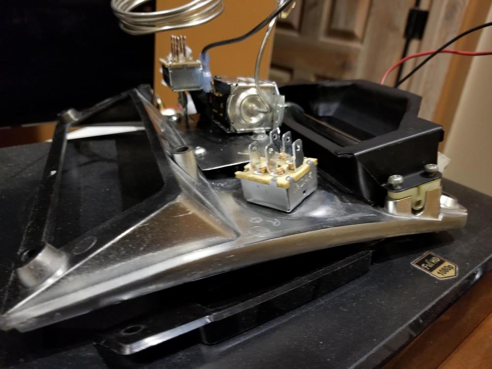
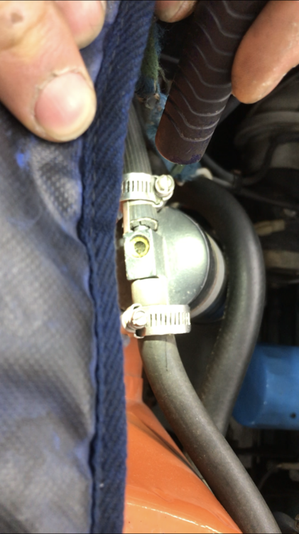
7 pointsThis forum has been very helpful to me. As a means of documenting some of what we have done and to help others avoid some of my mistakes I thought I would post the installation of a vintage gen II mini AC system. Background: My son and I are restoring a 1973 240z. We call it the bucket, as there was a significant amount of rust that had to be dealt with and our other choice – Money Pit was already taken. We are changing the color from 113 avocado green to mango orange, it has an L-28 engine and a 5 speed gear box. At this point: the car was taken to bare metal, metal replaced where required and any rust has been eliminated the rear clip is painted, front and rear suspension has been restored/upgraded and installed brake system has been restored/upgraded and installed half axles, differential, driveshaft, transmission, engine have been restored/upgraded and installed fuel system has been restored and is installed cooling system has been restored/upgraded and installed electrical harness has been restored/upgraded and the cockpit harness is installed When we purchased the car, it did have a non-working aftermarket AC system, probably installed at the dealership. We decided to replace the AC, defrost, and heater with an integrated system from Vintage Air. Vintage Air recommended a Gen II Mini The Gen II is a replacement for the original heater core, air box, and under-dash AC evap. As you can imagine the gen ii is quite a bit smaller than the original components, but it is a universal system and therefore it needs to be shoe horned into a space under the original dash. Because I removed so much original material, I thought that I would be able to fit the combination evaporator/heater and air box above the transmission tunnel and behind the instrument panel. This gets it away from the passenger footwell and centers the defrost and climate openings. I found someone that had done something similar so I was fairly confident that I would not have a fitment issue with the dash. Brackets are provided with the Gen II but I did not find them to be particularly useful. Mounting is fairly straightforward, but if you are like me sometimes it takes a few proto-types to get something that satisfies you. Mounting the Evaporator Once the evaporator is in place you can decide where hoses need to enter/exit the firewall. It is always nice to use the original holes, but you need to consider the radius of the bends for the hoses as they do not like to make sharp turns. I decided to install bulkheads for both the AC hoses and the heater hoses. I like this luxury because if the engine has to come out or if anything goes wrong with the evaporator/heater then disassembly stops at the firewall. Also if any of the hoses fail you don’t have to disconnect at the evaporator to replace an engine bay hose and vice versa. Working these stiff hoses and close connections under the dash is not the most comfortable task, The only downside that I can think of regarding bulkhead connections is that there are additional breaks in the hoses that now require some sort of mechanical connection and this is yet another opportunity for a leak. I did not have to cut any additional holes in the firewall but I would recommend that you buy individual bulkhead connectors as opposed to 2-way or 4-way bulkheads. This probably makes it easier to use the original holes. Bulkhead Connections water connections are behind the evap, compressor connections are near the main harness entry. Those are EZ-coils fitted on the hoses to help keep them from collapsing due to a sharp radius you can see the water connections on the passenger side of the engine just below the level of the valve cover. Compressor lines enter the bay just above the passenger frame rail. I would have preferred to do all of the hose routing with the engine out of the way, but I was concerned that I could not visualize every aspect. The AC compressor is a bit of a chore to mount so I will do that while the engine is on a stand. Here is what is being replaced – a Nissan bracket, and a sanden compressor. The original compressor is much lighter than most that were used in the day like York, but the original combination still weighs 24 lbs. Original Bracket and Compressor I tried to use the original bracket. Even though it is heavy and bulky it is clearly better because the compressor can be mounted so that it does not have to move to install a v-belt. There is an integral idler pulley that is adjustable. I spent valuable time cleaning the bracket and the pulley in preparation for painting, but alas I could not figure out a good way to modify it to accept the new compressor and properly align it with the engine pulley. The bracket that I purchased from Vintage is simple (no idler pulley) but it is made to convert a York bracket. Unfortunately, it does not line up with the bucket’s pulley. So my choices were to somehow modify the simple bracket or build a new bracket. I decided to attempt a mechanical solution as opposed to modifying the bracket by welding a piece on. The problem really has two pieces: the compressor must align with the engine pulley and because there is no Idler pulley it must rotate to install and adjust the v-belt. Here is what I came up with. It is 9lbs lighter. I will continue to look for a more elegant solution with an idler pulley, but I need to get the engine back in the car. NEW AC Bracket and Compressor With the engine and radiator in place it is an easy task to route the Compressor hoses to the bulkhead. Vintage offers a connect system called “easy clip”. I have not used this before but it allows me to construct all of the hoses myself without the usual expense of a crimping tool. This will make start-up of the AC system much simpler, because I will be able to go to a shop and only require evacuation, drying and filling to get the system working. This should take about an hour as opposed to waiting for someone to construct the crimp hoses and depend on someone else to route the hoses to my satisfaction. Hopefully, the easy clip system works well and does not leak. Condenser The condenser and drier were both part of the gen II kit. Bracketing the condenser was fairly easy. You need to take into account the holes in the radiator support as the hose that sources the drier must go through the support. It would have been nice to mount the drier ahead of the support where the air is coolest but it was more convenient for me to put it on the engine side. I converted to an aluminum radiator with an electric fan so I installed a trinary switch on the drier. So, the routing of the hoses is: Evap to Comp, Comp to condenser, condenser to drier and drier back to the evap. The route that I took was evap across the firewall to the comp mounted driver side low, from the compressor thru the radiator support across the condenser to a connection on the passenger side of the condenser from the condenser thru the radiator support to the drier, from the drier along the passenger frame rail to the firewall to the evap. That is a 2 row aluminum radiator painted black with a dual electric fan setup. I still think that it is strange to use a 2 row, but based on what I read I convinced myself that 2 rows were actually better than 3 or 4 for the same overall length and width. The condenser is visible here - in front of the radiator Climate Control Panel The last piece of the puzzle – mounting the controls. When this project began, I had no idea what I was going to do with regard to the climate control panel. Trust me this restoration has had enough challenges, but I wanted the controls to look they were part of the car. Originally, I envisioned the new panel hidden behind the original panel with mechanical linkages to control the system. I ordered a panel from vintage air, their least expensive. It allows for 4 slide type controls: AC compressor on/off combined with AC temperature control, Heater temperature control, Fan speed control, and Mode (defrost, feet, body, body+feet) control. Now that I have good handle on the mounting of the evaporator and know that the dash will fit without interfering with the evap I can consider using the original Datsun climate control panel which had the original mechanical controls for the vent, heater and defroster. The bucket had an aftermarket AC system, but it did not have anything integrated so the compressor control and the AC temperature control were all hung external to the dash. The Datsun climate control panel accommodates three slide controls: outside air, heater temperature, mode (defrost, feet, body, body+feet) control; and a rotary fan speed control. The controls for the original AC system were appended to the dash and did not compliment the look and feel of the car. The original climate control panel and the vintage air panel I decided that I was going to attempt to integrate the vintage air controls into the 240z panel. My control panel was not in very good shape so I decided to use it to trial fit everything. I opted for the luxury of replacing my panel with a new one. MSA does make one – it’s approximately $130. Its plastic, well built, but nothing special. They have a slightly more expensive version with chrome accents – I was not smart enough to order that version, so I spent more to have the fun of trying to do chrome accents myself. The first obvious difference between the original and the vintage controls is the fan control. I ordered a rotary fan switch from vintage air to replace the slider that I originally purchased. The hole in the 240z panel must be opened a bit to accommodate the vintage air control. If you go this route, remember to be careful as you are working with plastic, so cracking is a real possibility. Next, I removed each of the slide switches from the vintage air panel. In my opinion the best/easiest way to integrate them into the 240z panel was to create an intermediate metal panel to house the vintage air controls and then mount the intermediate panel onto the 240z plastic panel. The metal panel should help distribute the forces of the sliders and will allow me to more easily position the sliders where I need them. It’s not as easy as it sounds. The travel of the vintage air sliders is quite a bit smaller than the original 240z controls. I considered mounting the sliders a few inches back from the 240z panel which would make the slider travel more similar to the original but it complicated everything else so I rejected the idea. The length of the vintage air slider mechanisms is also different than the original 240z controls. The vintage air heater temperature control is a bit hooky in my opinion. It is mounted to the vintage air panel by being squeezed by their bracket. There is no provision to screw it to a panel. It’s quite small. I used thin aluminum sheet stock to build trial configurations. It’s easy to bend and easy to cut and you can expose a lot of issues very quickly by using a proto-typing process. The AC control is relatively large. I decided to fit it into the top slot of the plastic panel labeled “AIR”. In my opinion - this is where it fits best. You can mount it without a lot of difficulty with one exception – the length of the slide control is too short. If you choose to go this route don’t purchase the vintage air panel (it’s a waste of money), and when you order the controls make sure that they provide full length sliders. When they build a kit with their panel, they cut the sliders to fit their panel and it is too short for the Datsun panel. I very carefully bent the L shaped bracket flat. I then removed enough material from the bracket to allow the slider to protrude through the plastic panel enough so that I could attach a plastic knob to it. I wanted to use the original 240z knobs to help disguise the vintage air system. One of my knobs was cracked and so I searched for a replacement. I found some new ones at Banzai Motor Works that were reasonable. The heater temperature control will fit just below the AC control. I built a small aluminum bracket that pinches the heater control and attaches to the climate control panel. Lateral movement of the heater control is prevented by the aluminum bracket and vertical movement is prohibited because the heater control is held in place by the ac control above it. The mode control will fit in the climate control panel’s third (lowest) slot. Here is an image of the original control panel with all of the controls mounted to it. Also, you need to seal off the cowl vent because there is no provision for the vintage air system to utilize that vent. The only fresh air vent system that you will have will come from the vents on the driver and passenger side which are controlled by individual mechanical cables. These vents actually get their air thru the ducts to the opening in the radiator support. The bottom line is that the original 240Z panel will remain in-tact and the new system will seamlessly fit behind it. You will not be able to tell that the entire climate system has been upgraded. vintage air controls Integrated Panel CONCLUSION If you choose to upgrade your AC system and you opt to integrate the controls into the original climate control panel you can benefit from my mistakes. Do not order the panel/control kit. Instead order the individual switches with full length sliders. Make sure that you order the rotary fan control and not the slide fan control switch. In the spirit of full disclosure I have not fired-up the AC system yet. Having said that, based on previous experience I believe that Vintage Air has done a great job providing a terrific system with more than adequate documentation. I especially like the reduction in physical size and weight. I also like the electronic controls as opposed to mechanical – cable stretch and loose cable connections are a thing of the past. I appreciated being able to make my own compressor hoses (hope they are solid and do not leak). I do wish that they would come up with a universal compressor mount with an idler pulley. All in all, it is a great system. It takes a fair amount of time and effort to install, but I believe you will be happy with the result. I will try to answer any questions that you might have. Good Luck.


 7 points
 -
 Exactly. I was like all like T-Rex arms after driving Wayne's car at Zcon. Couldn't lift my elbows off my waist. Thankfully there's still enough range of motion at the elbow to get the drink high enough to sip.2 points
 -
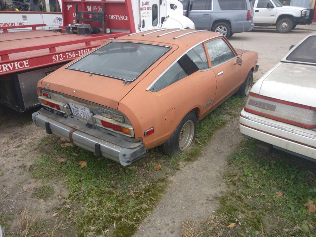
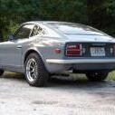
2 pointsFirst car I ever owned, tough as nails, easy to work on and boy did they ever like to rust.2 points
-
2 pointsI've been using 0000 steel wool on chrome, SS and glass for decades and have had no problems at all, it removes virtually everything that is on the surface, then a quick hand buff with a clean cloth and chrome polish and it is gleaming. Just make sure you have 4 zero's on the package.2 points
-
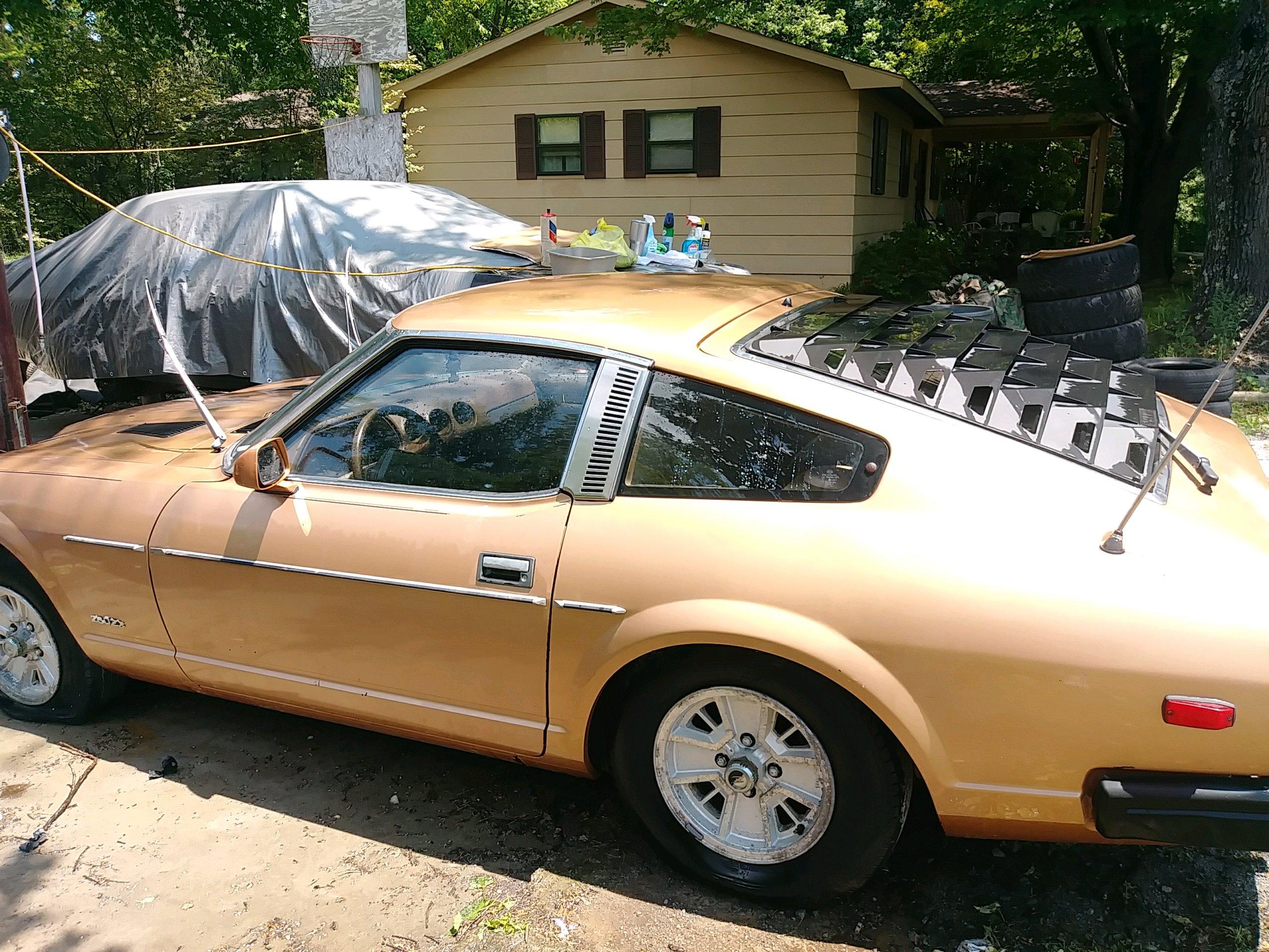
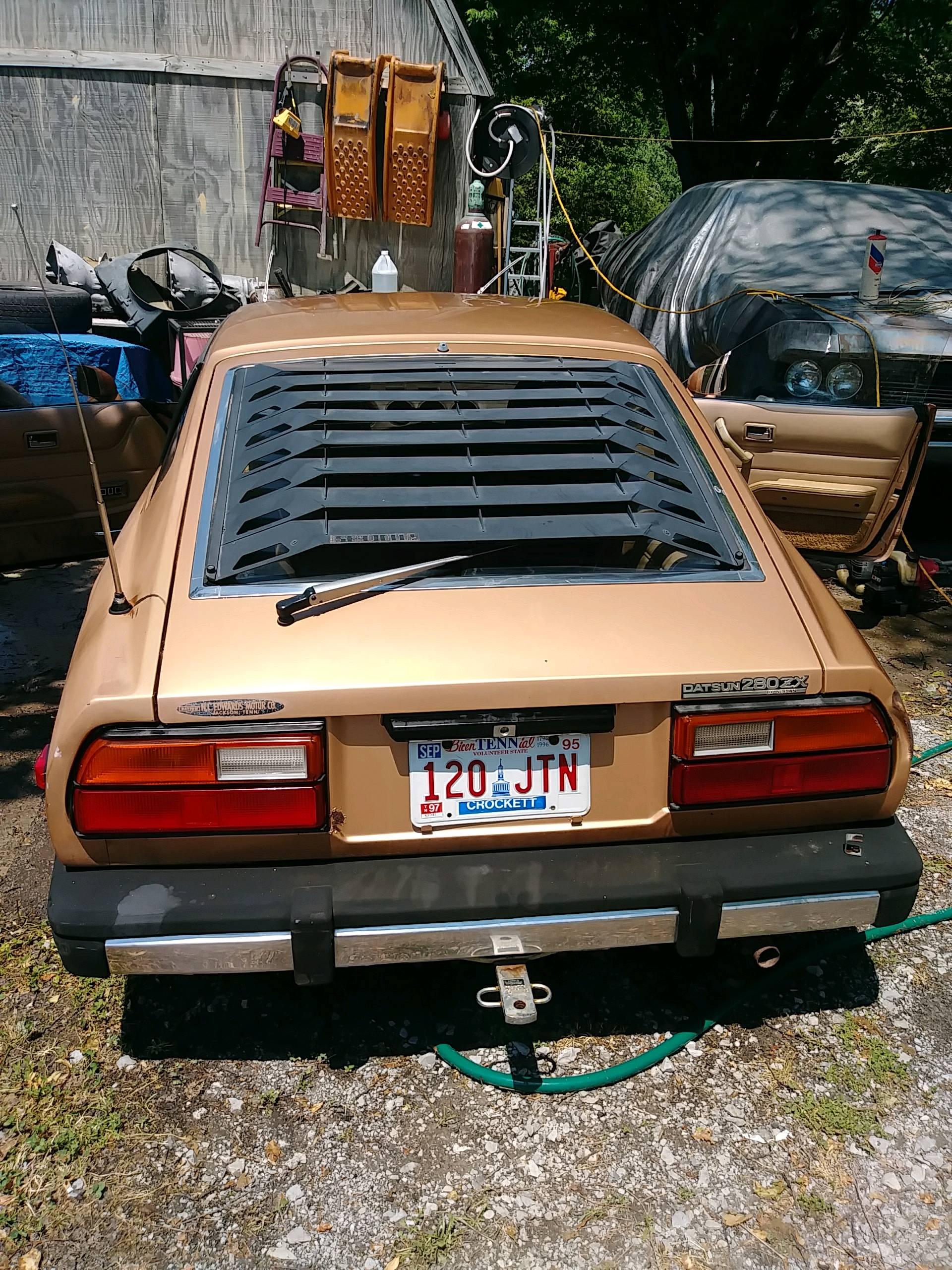
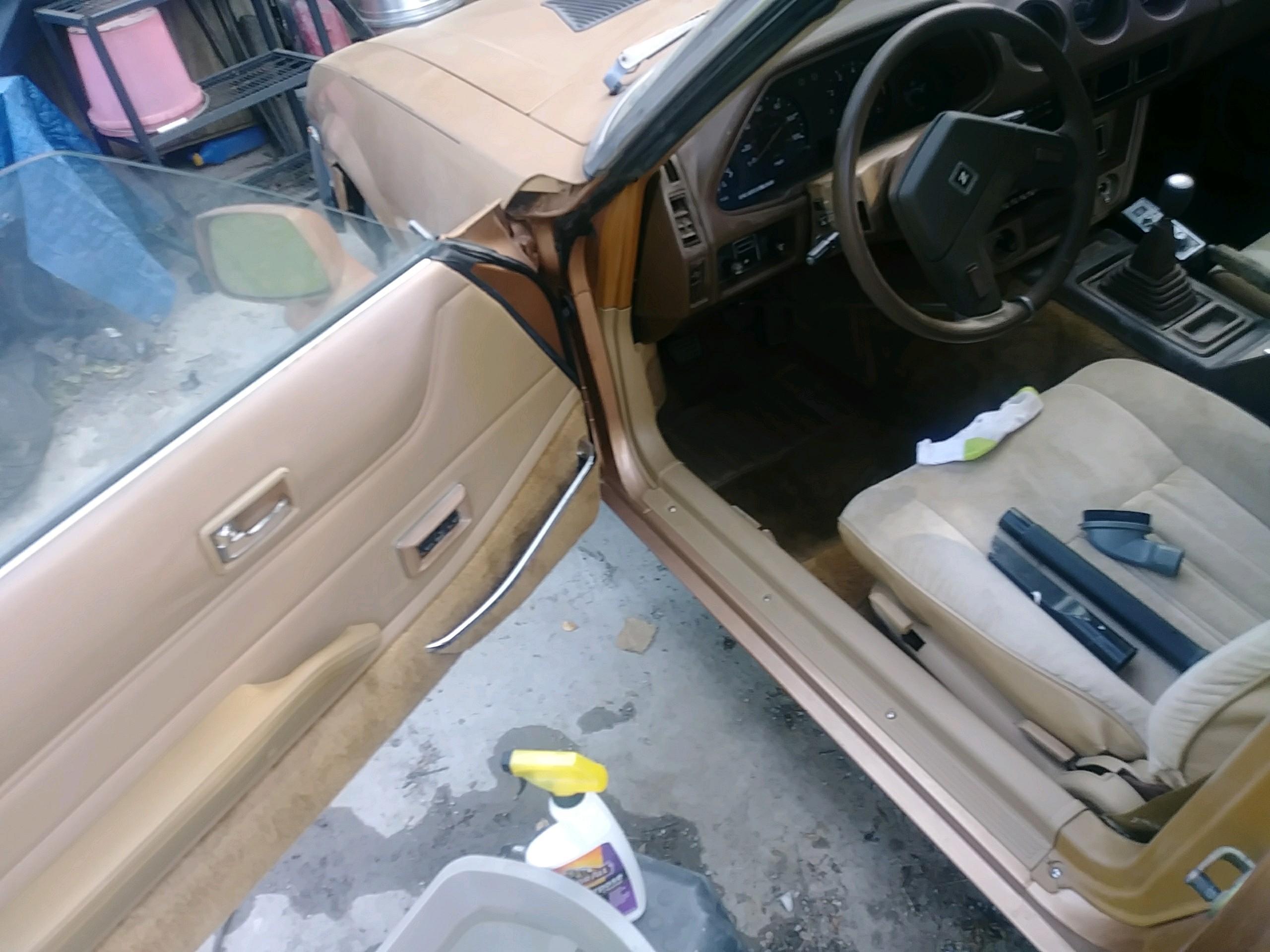
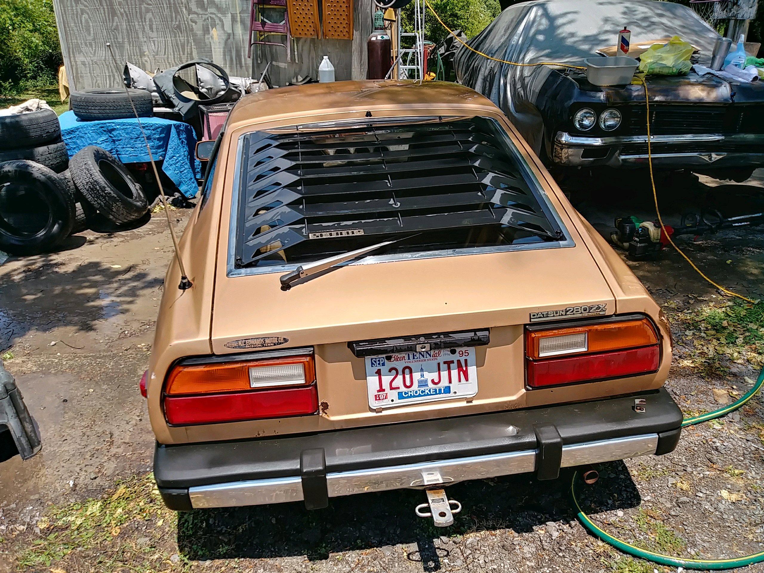
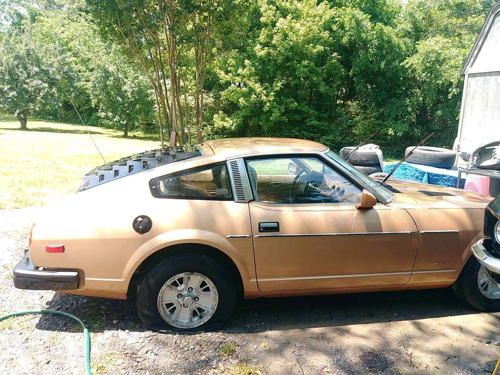
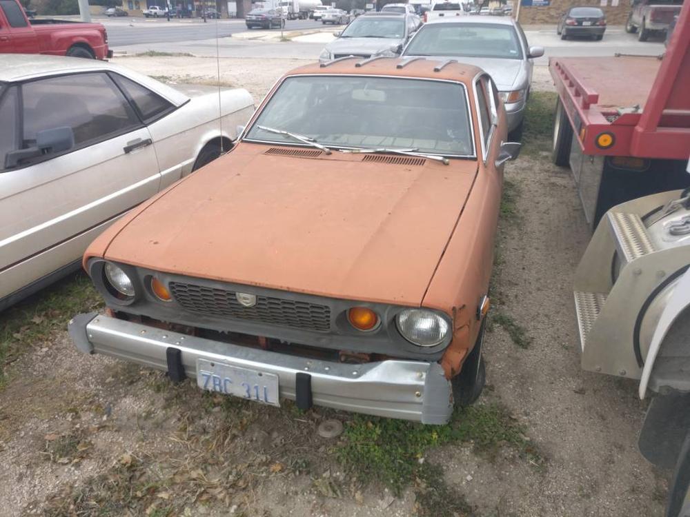
 1 pointWas a 1 owner Tennessee farm car all its life. Had sat for 21 yrs. Newer fuel tank, new fuel pump, injectors, front brake calipers, rotors, pads, hoses, ball joints, shock cartridges up front, struts in back, new clutch kit, gear oil in trans changed, new clutch slave cylinder, clutch master cylinder, brake master cylinder, vacuum lines, fan clutch, water pump, factory radiator in excellent condition. Has stock exhaust on the car. Even the catalytic converter. I have an eBay header and aluminum radiator to go with it. New rims and tires on it. I have the stock rims shown in pics. I have adjusted the valves and it runs and drives, shifts, stops and start great. Minimal rust on it. Some body damage around the rear passenger taillight and dented front driver fender. Call or text (731)432-1527 asking $4500 obo.


 1 point
 -
 1 pointIt depends upon what you're trying to do. If there were only someone who lived not that far away from you who understands S30 wiring...1 point
 -
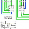
 1 pointI'm no electrical maven but it would seem that if you follow the Nissan diagram, you'll be incorporating some of the serious design flaws such as running high amperage power for lights and turnsignals thru the fuse box and combo switches. Many of us have cured those particular evils with aftermarket relay kits but there are still more weaknesses in the OE layout. You're moving from a 10 fuse setup to 21, it seems to make more sense to follow the guide of your new kit. Good luck with the project.1 point
 -
-

-
1 point
-
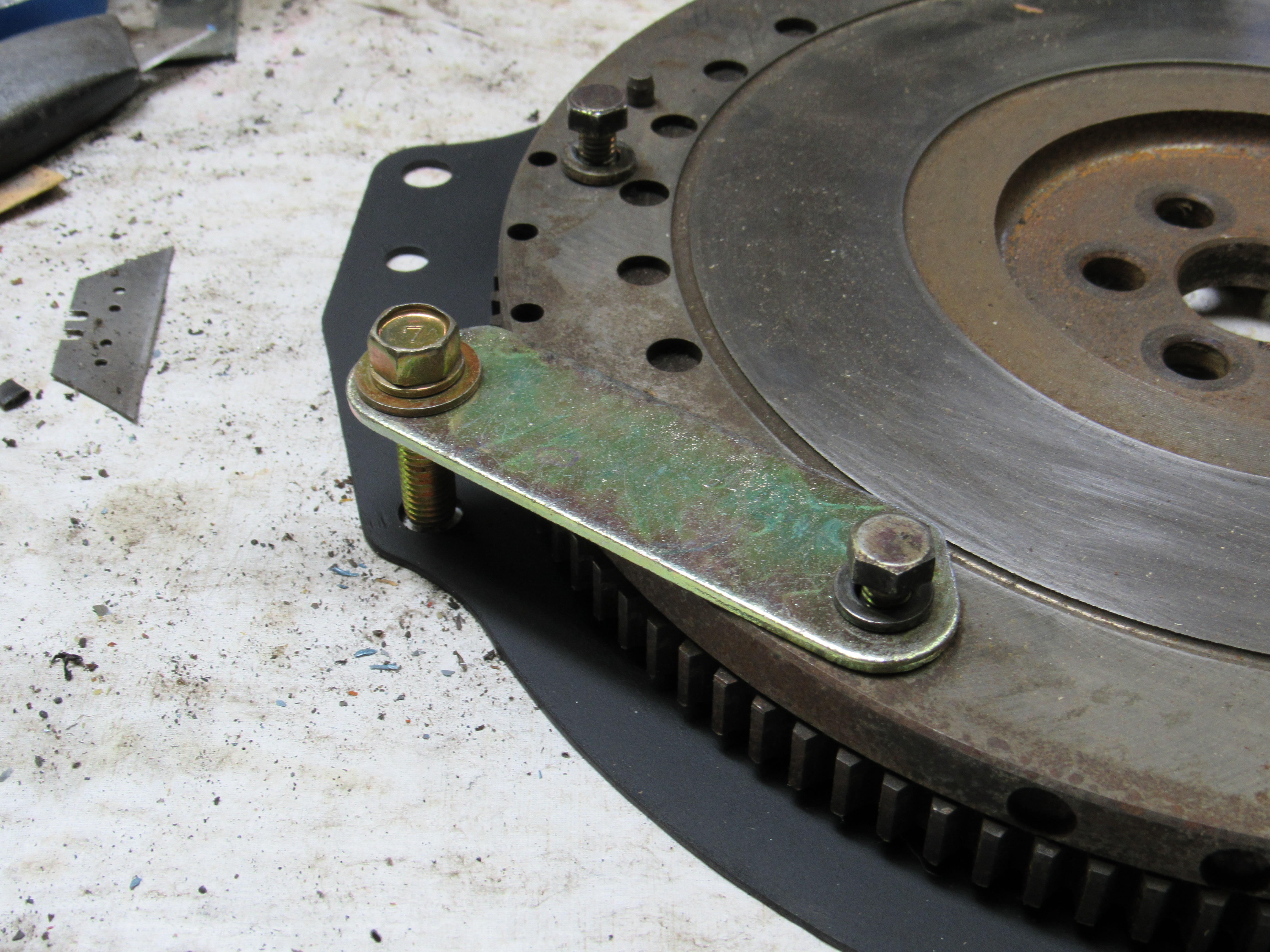
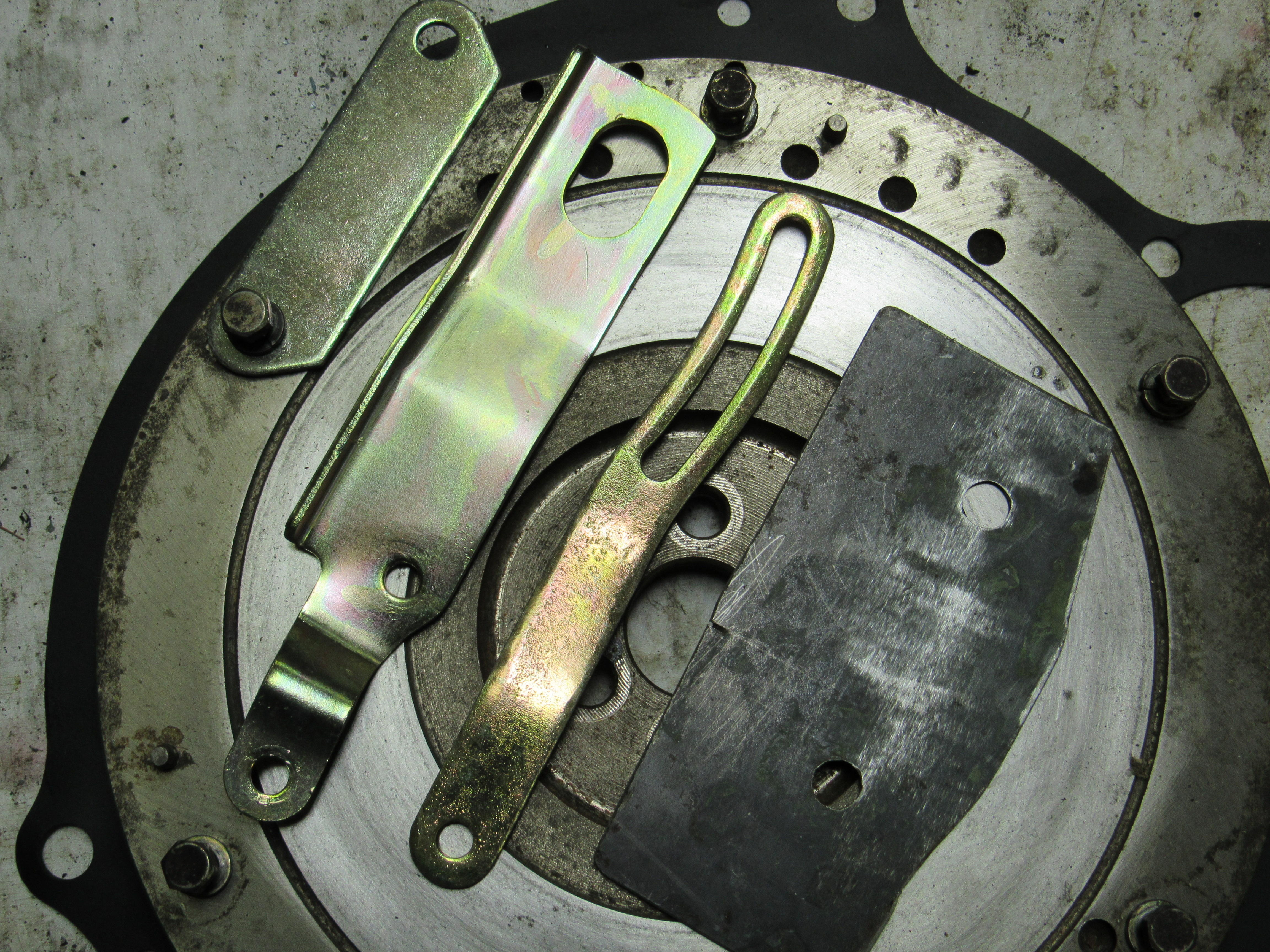
1 pointAny method of removing the flywheel bolts that uses the starter ring teeth comes with the risk of possibly breaking those teeth. This method was posted by one of the members here years ago, I can't get access to the back of the L28 at the moment but I think you'll get the idea. Our cars come with many pieces that will do the job well, even a scrap of metal with 2 holes drilled in it will work, You don't have to tighten the bolts hard and it best to use a spare bolt for the engine block hole just in case it bends a bit. Better a 25 cent bolt that a flywheel ring gear.


 1 point
 -
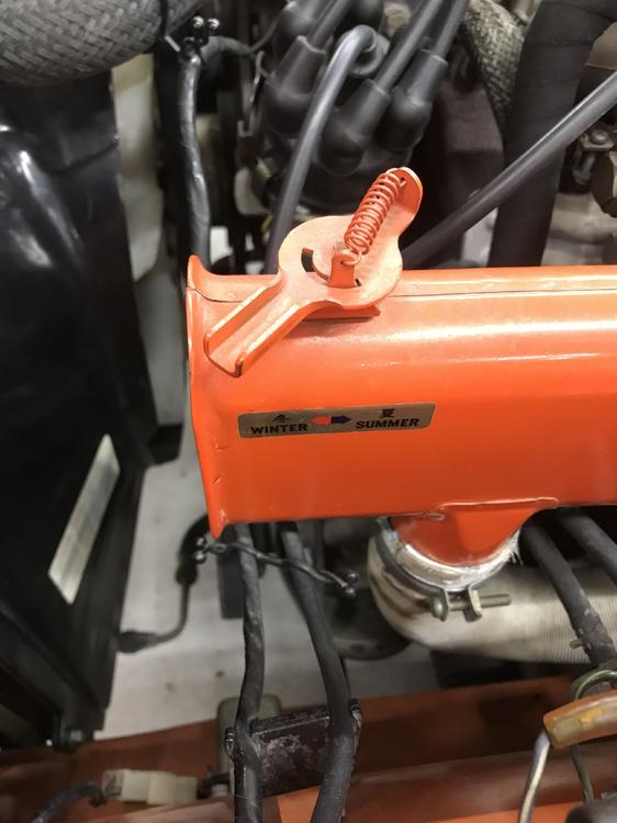
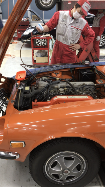
 1 pointSorry suddenly back to my 240Z story , I have a question about air cleaner horn flap , we do not have this flap in Japanese model , is this for a Northern Canadian customers ? R12 gas was filled by Mr.Okajima at Kyoto Nissan as usual. Kats
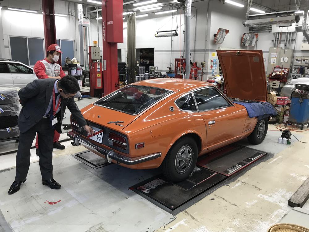
 1 point
 -
1 pointI don’t know much about Sanny ( B210 ) , but I know there are many hard core fanatics in Japan , modifying them, racing them . siteunseen , is that the car can rev up to 10000 rpm when going to 122 mph ? Type A engine ? Kats1 point
-
 1 point
 -
1 pointHaha, I guess I'm just too young to know about them... Thanks! Sent from my OP 3T using Classic Zcar Club mobile1 point
-
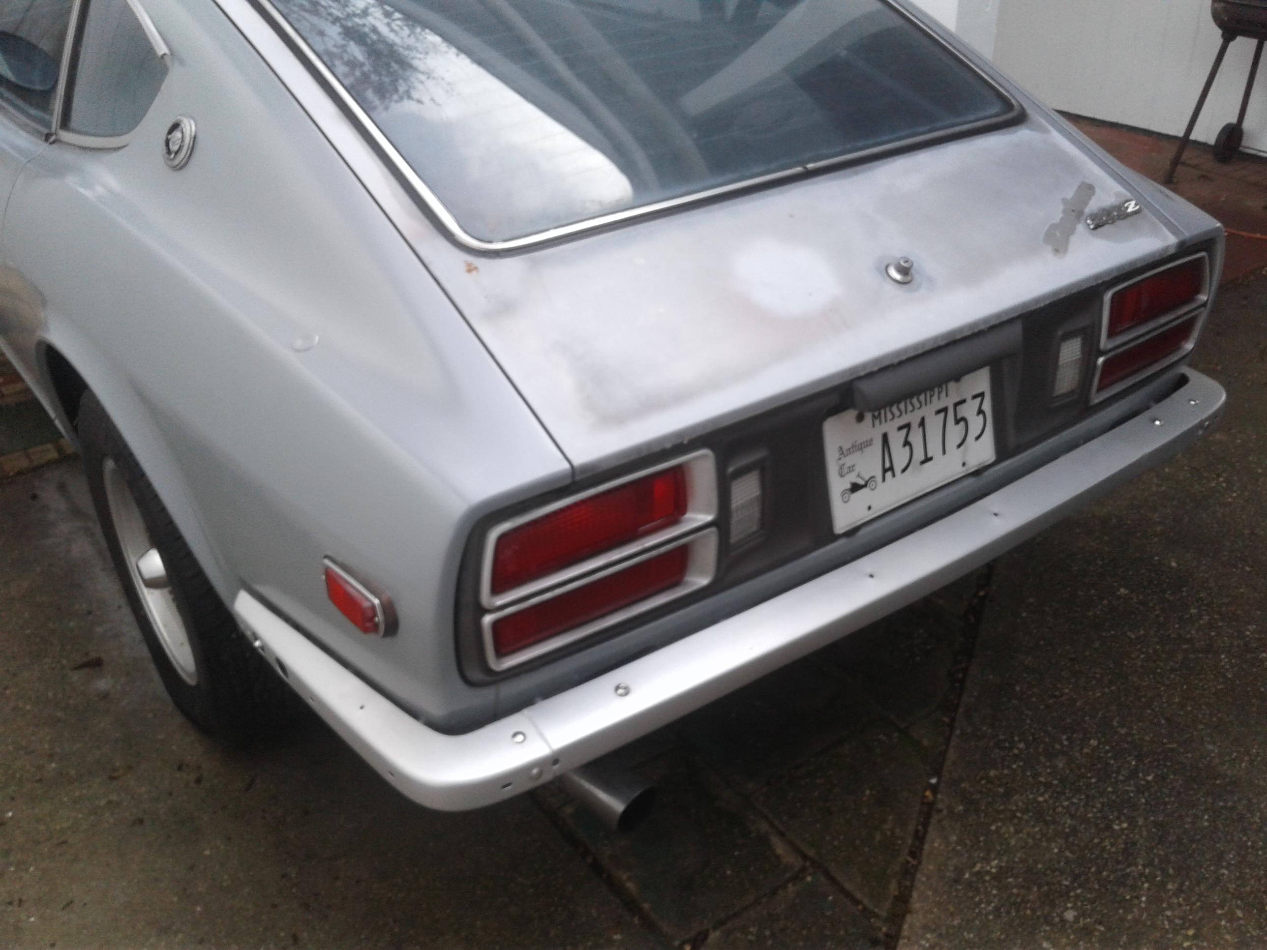
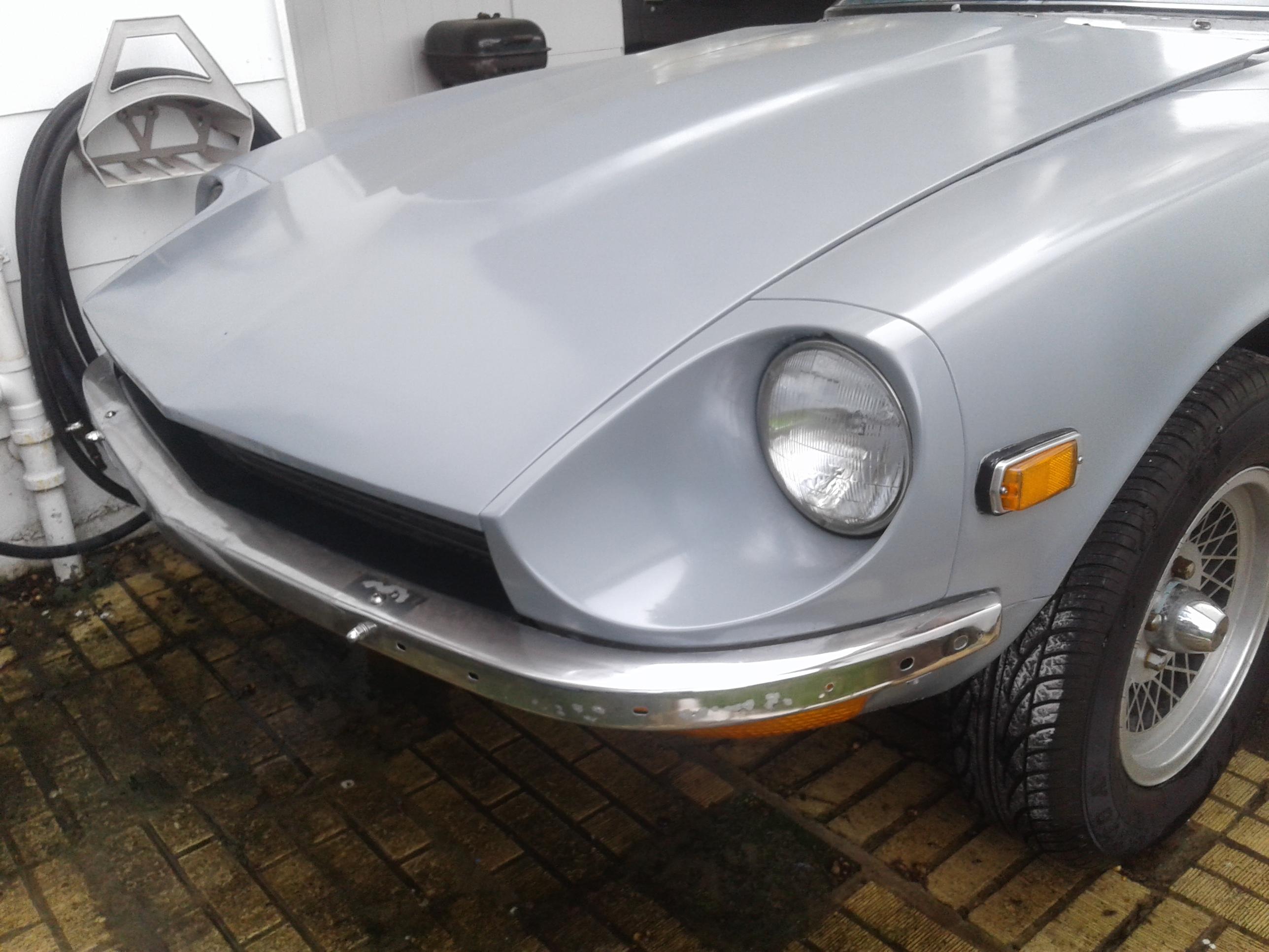
 1 pointThe car may be a 73 with an L28 block, but those are not 73 carbs. From what I can see they are 4 screw early SU round tops. So they're more like 70 - 71 carbs. @siteunseen 's pictures are pretty much like you want it to look when your done de-emmisioning it.1 point
 -
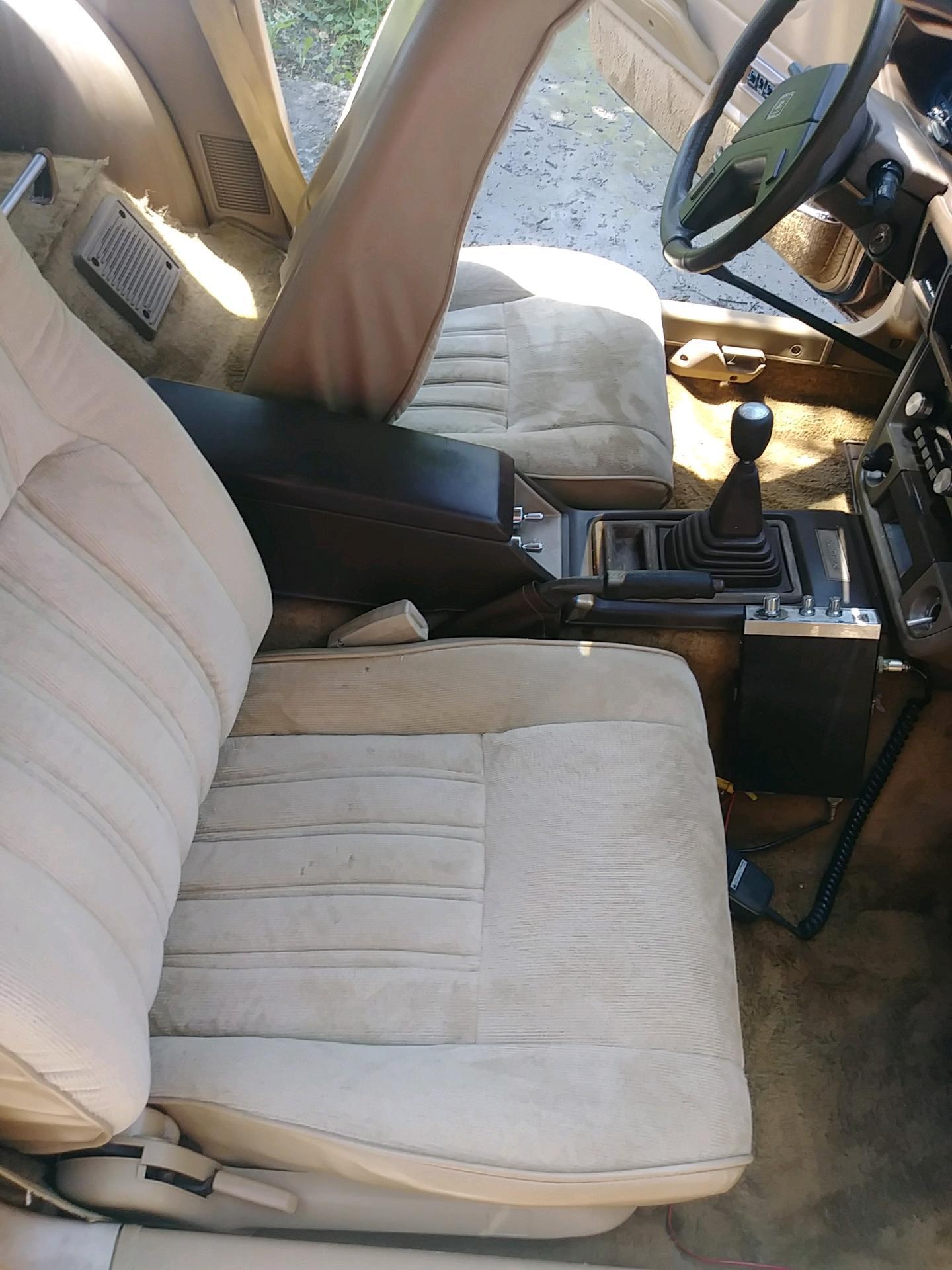
 1 pointThanks for the advice. This isn't my first Datsun I have had 4 280zx's so far. This is my 5th z car, but first Z car. I have had a lot of ups and downs with the previous ones and learned some of these lessons along the way. My drive behind this Z is I just think they are awesome cars and I wanted to own a Z since my first zx. I did a lot of modifying and body work on that one until I sold it. Then the rest of them never felt the same. I would find rust or something else to discourage me. But this being a Z makes it different. The end purpose of this car is to just have something I enjoy driving whenever I decide to drive it. It will be a weekend cruiser with Im sure some shows and track days in there. It will not be a garage or trailer queen at any point. I just love these cars and want a Z that fits what I think a Z should be. Again I appreciate the previous advice and all the future advice I will be getting. I do try to bag and document everything when I am messing with it so I know where it goes, but I am sure that at some point I will mess that up too.1 point
 -
 1 pointOMG... I have a new 401K account in my garage... oh wait, I only have 280 parts..... Guess I have to keep my day job.1 point
 -
 1 pointI made something like jonbill did from an old piece of trailer hitch hardware. Same concept, get a strong piece of metal that will jam in to a tooth. Be aware that Nissan used some pretty strong threadlocker from the factory install. Either that or somebody else did when they worked on mine. If it's never been off those bolts might take some real effort. The bolts should have been torqued to 100 ft-lbs so will need at least that to break free.
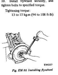 1 point
 -
 1 pointGet a box end wrench and a dead blow to simulate an impact wrench. Put wrench ( box end) on the bolt , hit wrench with 3lb dead blow to break bolts loose. It might take a couple of tries . I leave the spark plugs in to make the engine more difficult to turn over .1 point
 -
 cgsheen1: thank you. I have most, if not all the body-to-bumper pieces already. Currently, bumpers are just bolted to the 280 “crash shock” plates with two accessible bolts...an OK arrangement just to hang them. However the sides are just kinda “free floating” because I could not use the 280 body mountings. I never got any 260 side mount brackets (purchase did include front override bar and fairly decent rubber trim appearance and filler pieces). Therefore, I don’t have “donor” 260 braces to try and fabricate some small conversion piece at the body mounting ends of a 260 bracket to my single bolt 280. These possibly could be the easiest thing to have fabricated ... could anyone on this forum do this for me at a fair price? I would have to attempt sourcing good used early 260 brackets F&R... but potentially bumper distances, fillers fit, AND all mountings line up and direct mount to my 280. With my luck, that might seem the easiest but...would not be the best/practical/ reasonable $$ path....?. Any input on this? I think you are absolutely correct in your last post re: pushing sides to far forward by simple shock compression. Kills that Thanks Zed, Yes, I could either source used 260 bumper support braces to convert, taking bumpers (brackets)and car to some type of metal fabrication shop & sharing some visualization of goal. Asking them a fixed price for creation of a conversion or just building whole new brackets w/necessary side mountings. Asking them (no idea of how to identify trusted source) if they would create a “one of a kind” 4-pc custom job...for some “reasonable” cost. Perhaps only way to determine cost/ability of ever using existing 260 stuff-or is there some Z club member doing metal fabrications (or local person/place close to WNC area) that someone could refer me to and discuss how-to? I appreciate all the input I have received and truly trying not to discard any offered options. Trying very hard to remain hopeful of some positive $$ resolution before accepting my 260 bumpers only useful for 260 replacements and no conversions value! Only source of buyers=260 owners? Very hard to swallow until all experiences and input asked... My Thanks to all! Doug1 point
 -
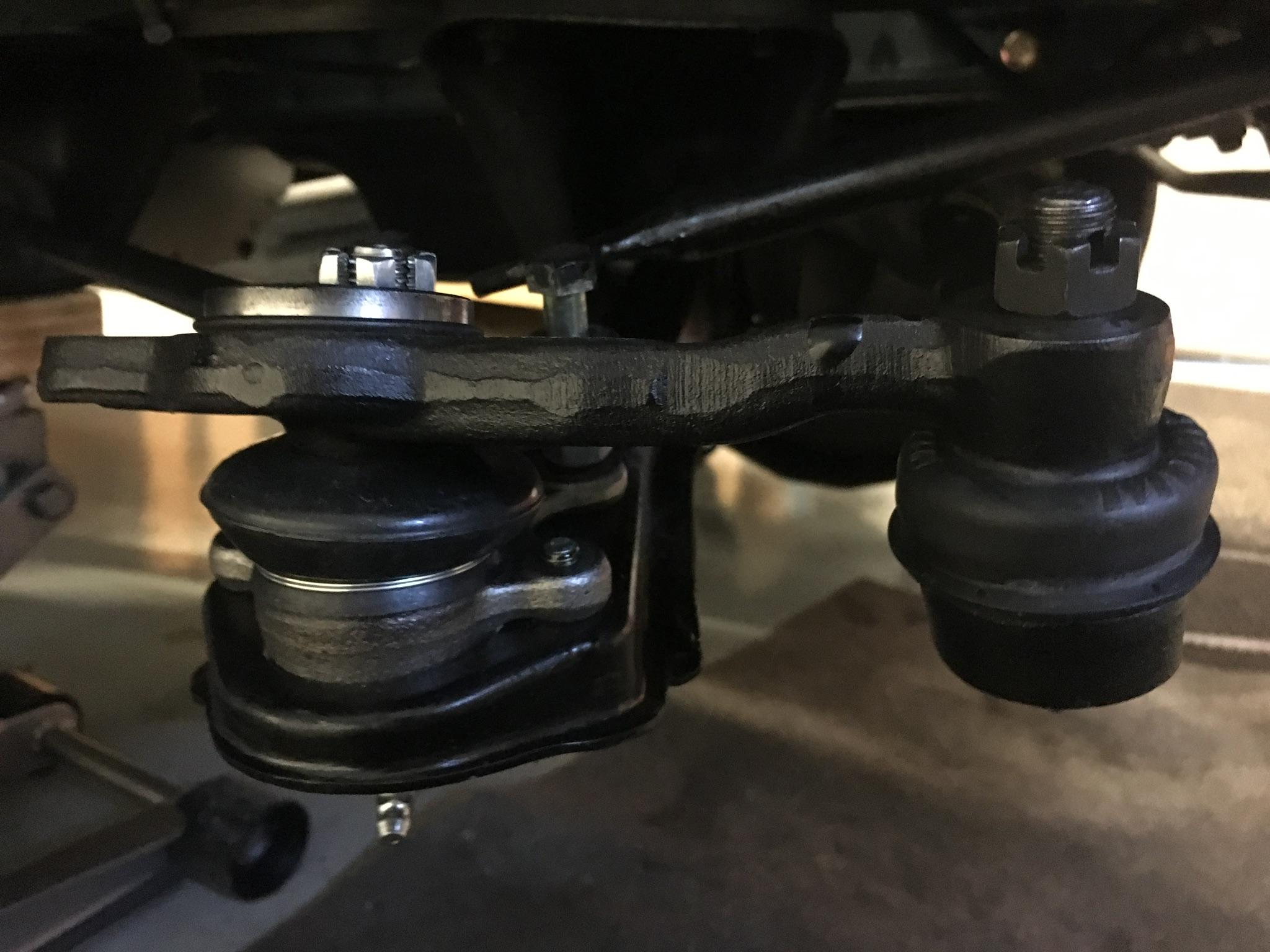
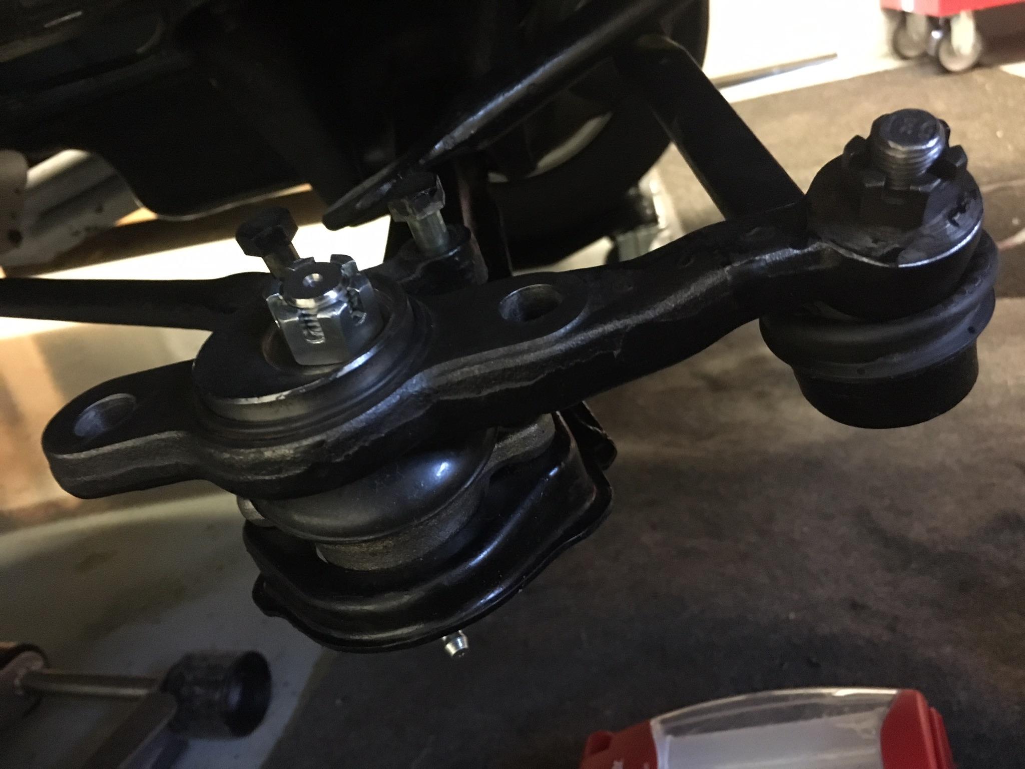
 1 pointNot sure what I would do with out all your help, sure enough the two greasy little screws were holding me up, also put the floor jack under to level it out and it came right off. Thank you.1 point
 -
 I believe that would push the ends back into / over the front wheel arch. IIRC, the front bumper "sides" are longer to compensate for the amount the bumper has been brought forward. It's been a few years since I abandoned my early 260 bumpers in favor of 240Z bumpers so I may be mis-remembering, but I think that's the case...1 point
 -
 The early 260 front bumpers can be pushed back to fit against the body if one drills the bumper shocks and squeezes the oil out of them. I think it's true of the back bumpers too but can't verify it yet.1 point
 -
 1 pointThose were a dime a dozen back in the day. I beat the hell out of a few myself. They were good gas mileage cars during the gas shortage days of the '70s. The fastest they would go is 122 mph, free falling dropped from a helicopter. Knock yourself out... https://en.wikipedia.org/wiki/Datsun_2101 point
 -
1 pointY'all are crazy going for cars like that. This is what you need! ? Saw it today, a Datsun b210. Just curious, do y'all know anything about it? Sent from my OP 3T using Classic Zcar Club mobile

 1 point
 -
 1 pointWelcome to forum. I don't think you'll get many smart arse comments on here and like was said earlier the people on the forum have a love for these cars and are motivated to help the community, so again welcome. I got on here about a year ago after buying a Z that I really had wanted for 20+ years. I asked plenty of stupid questions as I educated myself. Great people on this have guided me well on my path to restoring my car. My first question for you is, what motivated you to buy this car?..the answer will better lead people on here to what your original inspiration was. Capt Obvious had a great write up on the different paths people go with these cars when referring to a guy selling one in PA. I'll see if I can find it. Your intended usage will also be a driving factor. Daily Driver, Show Car, Weekender, Track Car and so on. You have a lot of work ahead of you, and it will require some endurance to see this through. Too many guys don't have the enduring motivation to see these project through properly. Recognize now that you are not Garage Monkey and will not be finished in 3 weeks or 3 months. These projects are sometimes a year or more into the making. I see your are already attacking the rust...the Achilles Heel of these cars. Another idea is to start a journal of your progress. I did this and its beneficial for several reasons. 1. After doing extensive research on topic but not being able act on it I was able to ensure I didn't have to do all the research again. E.g. What is a largest tire you can fit on a 280z and not rub the body without fender flares, and how will it impact steering and ride? I need tires but haven't bought them yet but I know when its time, exactly what I need because its in my journal. 2. It will help you troubleshoot your problems and finally recall things you have forgotten. My final piece of advice. Pictures pictures.....take more than you need before you disassemble something. Picture are free, so don't screw this up. Your memory will fail you I promise, especially if pulled a part off 3 months ago. Example, I dissembled my 77 fuel rail to clean it, and replace the rubber hose pieces. it sat for maybe 3 weeks apart and even with pictures I wasn't 100% confident I was putting it back together right. Without pics I would have been on this forum asking stupid questions again.1 point
 -
1 pointType 33 Only 18 produced about $10 mil https://uncrate.com/1967-alfa-romeo-tipo-33-stradale-continuation/1 point
-
They look similar, but they're not the same. They are shaped differently because they were pushed farther forward and mounted on pistons to meet the new US crash standards. They should mount on a 280 much like they do a 260, but they will remain pushed away from the front of the car. The early 260 had various "filler" pieces to cover the newly increased gap between the bumper and body (and grill). I doubt you could get the early 260Z front bumper to fit tight to the body like a 240 bumper.1 point
-
 1 pointOne more thing to think about before you go too far, is painting the floor. Makes it much easier to clean up and looks better for longer, but it is pretty hard to do once you start filling it ?1 point
 -
1 pointThat's a beautiful place. I love the landscaping around the house. Your shop is 2 1/2 times larger than mine! what I could hoard up in there! I would locate the compressor outside, but it needs to be protected from freezing. It makes it hard to start up and residual water can freeze in the lines. Distributed air is really nice. Also a lot of wall outlets 44" off the floor. That way there is counter height power everywhere. Good work benches a must. A metal topped bench is really nice. I agree on ventilation. I also want as much light as I can get. I want operating room bright. I would switch them on multiple switches so I can run what I want and get it brighter when needed. Enclosed storage is nice or even a dedicated parts room. You could make the ceiling of the parts room the mezzanine area like Jeff suggested. I can help you size the framing if you need help. I might want a partition to keep tractors, mowers and small engine tools separate from the shop area with separate access doors. Some 220v power for a good welder. Hot and cold water and a bathroom. I also have a stacked washer dryer in my shop bathroom. I wash grungy rags, drop clothes and shop towels in it1 point
-
 1 point