Leaderboard
-


240260280
Free Member15Points4,441Posts -


siteunseen
Free Member8Points14,903Posts -
Dave WM
Free Member8Points3,591Posts -

Captain Obvious
Free Member6Points9,848Posts
Popular Content
Showing content with the highest reputation on 03/18/2019 in Posts
-
5 pointsMy Dad told me when he was younger somehow or another they put plugs in the exhaust and made fireballs come out the pipes. My Dad bullshits me a lot though. Pretty funny now that he's 80 and nuttier than a squirrel's turd.5 points
-
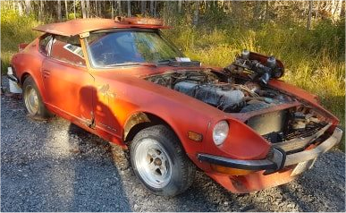
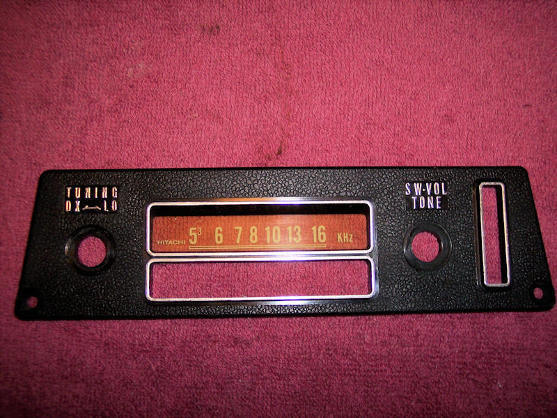
Bought a parts Sept 1970 240z to help with #147 resto. Seems to have early radio and antenna switch. Fingers crossed on the 2400 Valve Cover. I have not seen the engine yet and Sept is the final month of the 2400 cover.

 5 points
 -
4 points
-
Helped my buddy with BRE tribute. Triple Carb Linkage finished. Engine Electrical 3/4 Finished Lights connected (lots of splicing, crimping, soldering) Headlights Installed Front Turn lights installed Built 1 good licence plate lam assembly from 3 bad ones. Antenna coax fished Window bump stops installed Good day!4 points
-
 3 points........and there is absolutely nothing in the Universe nuttier than a squirrel’s turd! Cliff, I hope you never leave this site ?3 points
 -
 3 pointsNo problem at all. One of the good things about this forum is we get to discuss issues like this. I find it interesting reading and I have learnt a lot about these fusible links the last couple of days.3 points
 -
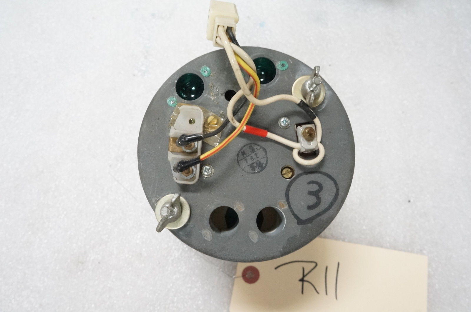
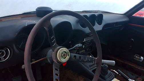
3 pointsI'm assuming we're talking about an early style inductive pickup style tacho? Back side looks like this, right?: If that's the case, then you really only need to make connection to two wires (not four). Just to get the engine to run, the only two you need to connect to are the two white wires. The one with the red tape should come from the ignition switch, and the one with the black stripe should go to the (+) side of the coil. If you don't connect the other two wires (Y/R and B), the tacho itself won't work, but that shouldn't keep the engine from running. Will just keep the tach at 0.
 3 points
 -
3 points
-
 3 pointsHi All, Big "Thank You" to Nomad, took the time to help another Datsun nut. 10 mins in my garage looking at the engine and discovered my throttle linkage was still slightly engaged, fixed. Pulled the distributor and adjusted the plate bolt so we had additional advancement on the timing and showed up with a set of SU, so he could explain the internal issues and working of the carbs. Engine is purring and we took the car out for it's maiden voyage (around the corner). Still need minor adjustments to the float levels as engine is running slightly lean but it's running. Where can I locate a new/used (working) vacuum advance for the distributor? VA is currently moving but too weak to advance the plate. Thanks to all who have given great direction on SU's.3 points
 -
the ground connections are all over the place, and there is not a real good test for them. Treat them after going thru the stuff already if nothing helps. The only way to test is to wiggle to see if they are broken, clean the spade and make sure you have good contact with the chassis ground. The really tough dogs are things like the grounds. Unrelated but still interesting, I used to do a lot of vintage electronic repairs on old TV's, vacuum tube stuff. In one set I had a very slow moving hum bar (horz bar moving upwards thru the picture, distorting the image). Generally speaking they were a result of a DC power supply that had excessive AC ripple to it. I ended up replacing the filament current with DC from a 6v battery pack before I got rid of it. Then I started trying each tube going back to AC for the filaments one at a time. when I get to the vert sweep board, it finally returned. The final analysis was there was a loose screw that secured a printed circuit board ground, not firm enough, and the filaments shared the ground stake. This low resistance allowed just enough hum to get into the ground circuit of the vert sweep tube, result, hum bar. tight the screw and bar goes away (I soldered a buss to it anyway, dumb design IMHO for rely on pressure to maintain a ground but that is EXACTLY what our cars do. Now with the car a slightly imperfect ground does not show up like it would on a CRT, but the point is pressure contacts for grounds are suspect.2 points
-
just watched the videos you def want to listen for injectors all clicking use a stethoscope. IF all click, disable one injector at a time and see how it effect idle (load test). will know a lot more based on the above answers AND a reading of the plugs. Regarding hard starting, this can be a real bear. I fought with it for a long time, I refer to it as intermittent starting, so after you get it to idle smooth and the idle bleed air working you can determine if its hard starting always OR intermittent starting (sometimes it will start right up). The good news is these engines are extremely easy to work on and the EFI works really well when everything is in spec. The bad thing is the ECU operates in "open loop system" there is no feedback on what the actual A/F ratio is so sensors must be operating correctly, the ECU can not "Learn" or "Correct" for any problems. Rough running has to be: Compression (a compression check is always a good idea). Fuel pressure readings ( both with engine off and running will narrow this down) and all the EFI Air (really proper air metering) Spark (plugs/wires/dist/timing) you are on the right track just do one thing at a time. Note we forgot to mention grounds, HUGE issue is wire and connectors and grounds. This is one thing the FSM does not go into, I suppose since no one figured the wire harness had to last 45 year or longer. there are several grounds and connectors. Just checking things can cause breaks and lets also discuss NEVER clean the engine with water, no pressure washing, leave it dirty.2 points
-
 2 points
 -
 2 pointsThank you - I have been blessed by your skillful review and I'm confident we are at the end of the revisions. I'm pretty sure you'd sleep better at ZCon... LOL.... Seriously, a huge thank you to you and Chas for being so patient with me with this revision. A special kudo's goes out to @EuroDat for starting the recent fusible link thread to confirm what was already suspected. I also wish to thank all of the private messages I have received regarding this diagram. I appreciate and am also humbled by all the kind words regarding this diagram.2 points
 -
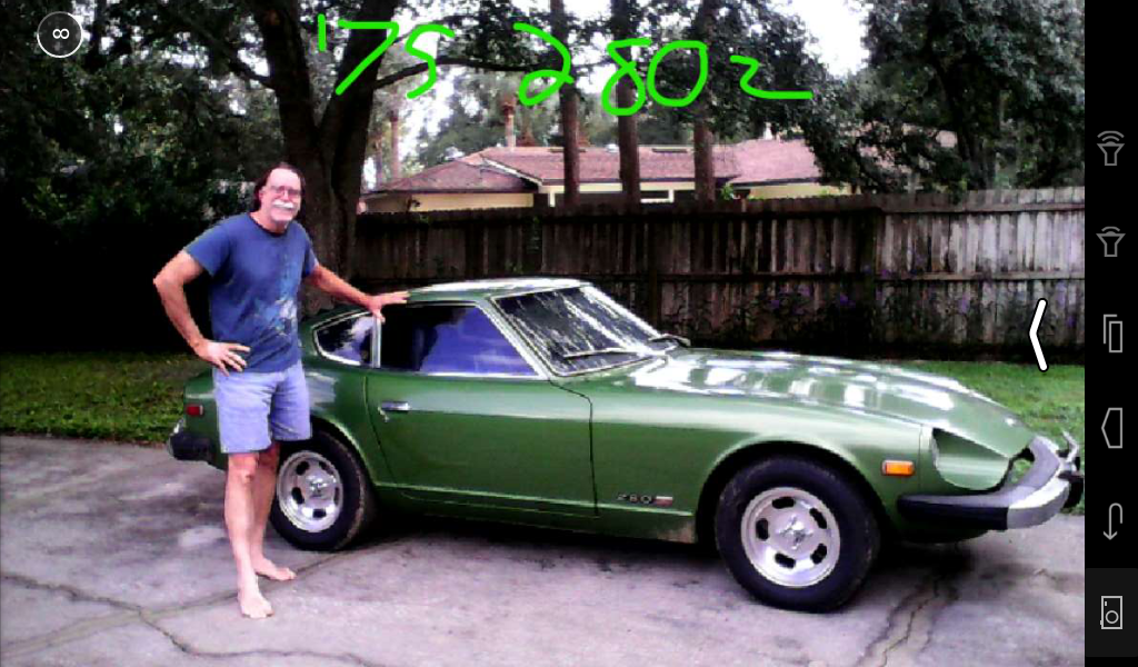
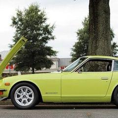
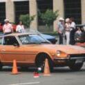
1 pointYes, Citizen Z is quite a character. I didn’t know I was going for a photo shoot when I drove up to see him. He is a Z enthusiast for sure. Funny thing is that when I went to see him I saw this 1970 he had and told him if he ever considered selling to let me know. Well I have it now. I miss those Mikunis , but can’t keep everything , I’m supporting a college kid1 point
-
 1 point
 -
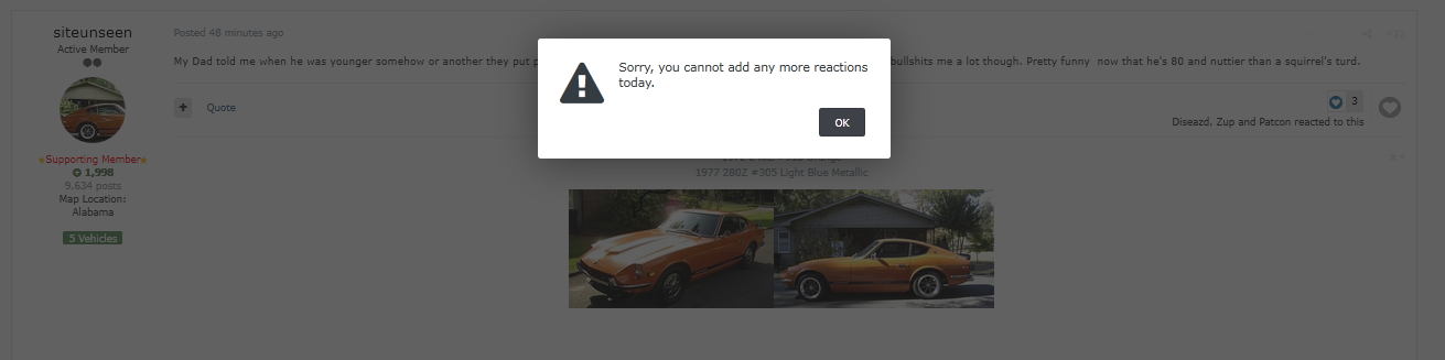
1 pointSorry Cliff, the site says I am not allowed to like you today ? Nuts! ? ?️?️
 1 point
 -
 You mentioned fuel and I don't wan to muddy things up but you might consider a bottle of fuel treatment in case you got some water in the last fill up. With the help you already have, you should be able to get this sorted. Just keep trying what they ask and feed the results back.1 point
 -
1 pointYeah, that can happen. They get rusty and then they self demolish. You could get by on points for a while but the electronic distributor is better and hotter. You would need to add the ballast resistor back in with the right coil if you want the points to last. Congrats on getting it to run!1 point
-
 1 pointPerfect. That is exactly what I am looking for. So currently I have power to the yellow/red wire but nothing coming in from the white/red, so that will be my task today to find out why that doesn't have power. FYI, I got it started yesterday!!!! I had to switch back to the old points dizzy and I was using the wrong coil and no ballast resistor, but it starts!!! Not sure if I will continue to mess with the electronic one I have at the moment as I pulled it apart and there is a lot of rust down in the bottom and the magnet is in 10 bits. I may have to look for a new refurbished one, or look for an alternative.1 point
 -
 Hi and welcome. Sorry you are having problems with your new 280. Keep this in mind though. it ran well recently so chances are you will get this sorted out and it will run well again. It worries me a bit that the prior mechanic wrote that they leaned the mixture. There really isn't a way to do that without screwing with the AFM which causes all sorts of other problems. Hopefully he did nothing. FYI, I watched your video. It sounds a lot like my 75 did at one point. I like your list of things to check this weekend. I would also remove the AFM boot(s) and check the inside of the AFM to see whether the Flap is stuck open. It should close when car is off and move freely up and down. I have seen an intake (not exhaust) backfire in a 280 cause the AFM flap to bend slightly. When this happens it can get stuck open. If it gets stuck open the car meters all the time like you are at WOT. My 75 had this problem and ran very much like yours in the video. Best of luck. Don't get discouraged. You are going to really enjoy the car once you get it sorted.1 point
 -
 1 point
 -
 1 point
 -
1 point
-
1 pointMSA sells a seal kit I have used successfully to refresh my valve. https://www.thezstore.com/page/TZS/PROD/24-5556 Apologies for the multiple posts. When I hit save, didn't work as I usually see. Sorry.1 point
-
 1 pointI had a great experience with my SU's with the stroker motor. Nearly equal performance in the low/mid range as the Mikuni 44's I had previously, excellent mileage, easy starting etc. AFR's with N47 needles on cruise at 15'ish, 12-13 at WOT1 point
 -
 1 pointHerman, I don't think the people doing the dashboards frequent this forum. You might try contacting Hung Vu via Facebook: https://www.facebook.com/hungdvu1 point
 -
Sounds like a good list. At least the car had some maintenance, maybe not recent, but some engines get no love. The AFM boots crack where you can’t see it, but maybe feel it, or remove and inspect.1 point
-
also check the condition of the boot from the AFM to the TB for cracks, unmetered air is covered in the FSM. On diagnostic that is often used is try removing the oil cap while idling. If the system is working properly the engine should sputter and die. if it runs better then you have a too much fuel situation. if it has no effect at all then its just running a tad rich at idle.1 point
-
Next most common is leaking FPR. odd readings that are not effected by vacuum would be a clue, but a definitive test is to detach the vacuum lead and look for leaks. checking the cold start valve is easy just pull it and make sure its not leaking. should not fire at all if temps are over about 70f1 point
-
Number one issue on rich running is the water temp sensor, not the sending unit for the gauge but the one that tells the ECU how cold the engine is. The FSM tells how to check and what reading to expect for given temps, Test at the ECU 36 pin connector with a good volt/ohm meter.1 point
-
1 point
-
1 point
-
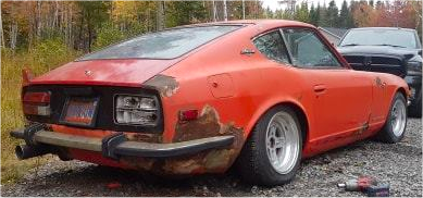
1 pointI remember your car. If it runs good put up some pictures and you'll get so many opinions you could figure out a happy medium. Seems like it was a respray red with automatic transmission?1 point
-
 1 pointIt is also the stock one for the 69-70 HLS30-UN. Conedodger I sent you a pm1 point
 -
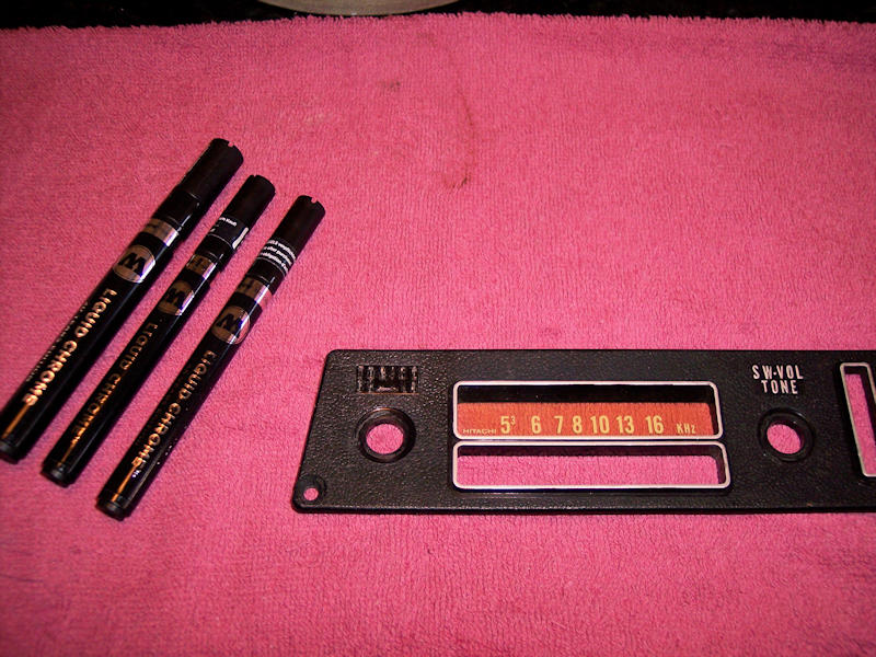
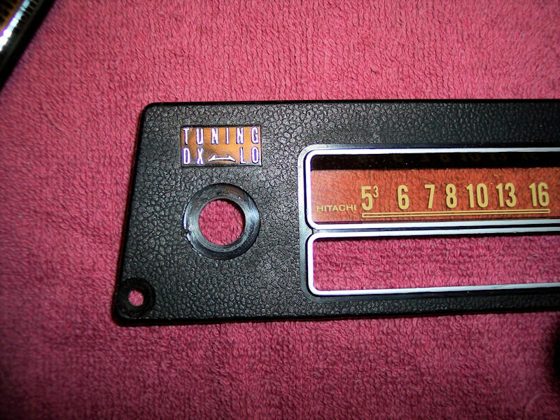
 Dan - Here's the update on the Molotow Chrome Pens: I thoroughly cleaned the lettering area at the top left with rubbing alcohol and a q-tip, most of the silver Sharpie and any prior chrome came off. Used the 1mm pen to cover the text. Cleaned the rest of the plate - note the silver Sharpie did not come off the long lines. Finished the text at top right with the 1mm pen and the long lines with the 2mm pen. I'm well pleased with the outcome - a very shiny chrome finish. I highly recommend this product, will be using it to update other areas in my car! Jim
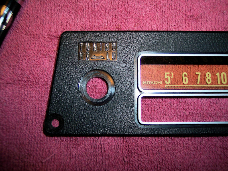
 1 point
 -
1 pointYou should call Dr. Nichols at Plexicorp. I think they're based in San Francisco.1 point
-
1 pointNow that all the (known) issues have been addressed and edited, I have updated Revision N to the download section. Changes to Revision N 1) Fixed wire colors going to oil pressure sender and tachometer resistor. 2) Changed fusible link positions to reflect correct positions on vehicle. 3) Changed internal picture of alternator. N77ZCAR-WIRING.pdf1 point
-
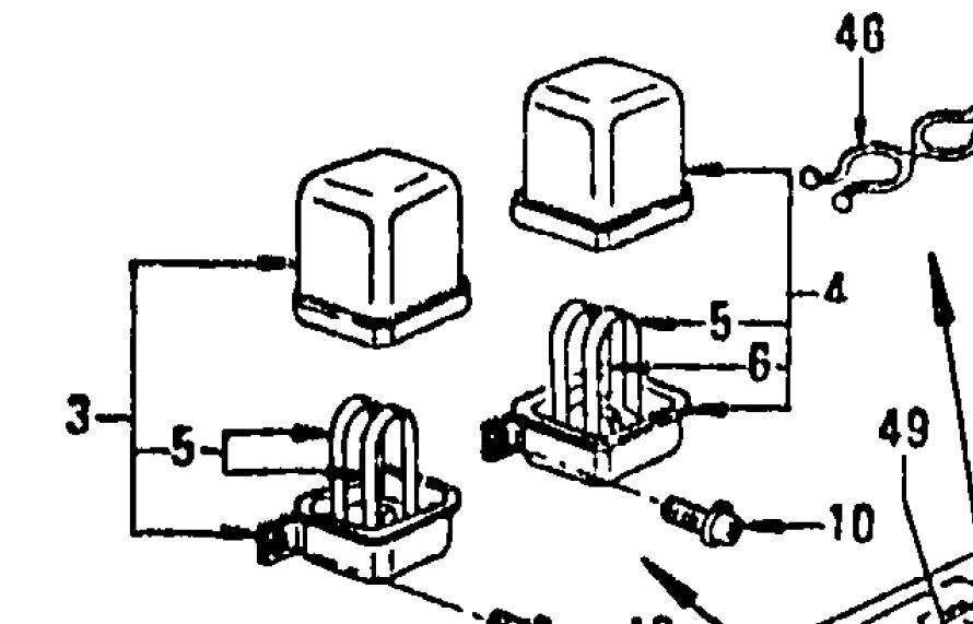
1 pointYes, indeed. I (wrongly) *thought* that you were looking at the table, and either was dyslexic or typed in the information you saw backwards. Until I opened the fiche, zoomed into that feature to 150%, it became clear to me at that point that there were 3 key #5 and one key 6 in the picture. With all the information discussed earlier, we can safely assume that the key numbers shown in the picture area are backwards. I apologize for responding that way, it was uncalled for, as well as inappropriate to add in this discussion.
 1 point
 -
 1 pointAnd without these forums everyone has to reinvent the wheel each time they come to this problem.1 point
 -
1 pointNo kidding. I think I tore a rotator cuff just looking at that pic.1 point
-
 1 point
 -
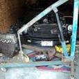
1 pointWhy yes I did! A chorus of forum voices echoed through my head as I prepped the piece... "did you mark the mating ends?", "did you mark each end separately for tranny and diff?" ... I also removed a whack of undercoating over-spray from the shaft. That must have been an issue with balance, so much of it on one side versus the other... yeesh.1 point
-
 1 pointMight as well get the kinks worked out on a stockish motor than on a built one. All the wiring is exactly the same. But at that price I would go with an assembled MS3 or MS3X which can do fuel and ignition. Sent from my iPhone using Classic Zcar Club mobile Correcting a word corrected by auto correct1 point
 -
1 pointCan't talk now, gotta get the oven back in the house before the wife gets home....1 point
-
 For the pragmatist, there’s not really a reason anymore to wrap a bundle of wires with tape. Just go to your local hardware store and buy some of that split, corrugated plastic sheathing. The ‘woven plastic’ sleeve is another contemporary alternative to tape. Re-taping a wiring harness with tape is for purists only. Decide which camp you belong to and proceed accordingly. Adhesive-backed electrical tape doesn't really belong in the engine compartment of a car. Sure, it'll look good after you've finished. And it will probably continue to look good for a few months afterwards. Over time, though, it's said that the temps under the hood will cause the adhesive to begin to weep out of the seams, after which the harness becomes a grime magnet and a gooey mess (won't be easy to clean either, I expect). In hotter climates, this may even be a problem for the under-dash wiring harness. I recommend that you look into using 'loom tape'. ‘Loom tape’ is just wider-than-normal pvc electrical tape that uses no adhesive. Back ‘in the day’, this is what vehicle manufacturers (including Nissan) used. Loom tape is more expensive than high-end electrical tape, but it’s still relatively inexpensive in the grand scheme of ‘things automotive’. I bought mine from a muscle car restoration parts supplier located north of Toronto. You should have no difficulty finding a comparable supplier in your own area. A 100’ roll sells for about US$13.00. Find vendors by searching on, ‘automotive loom tape’. Loom tape is typically 1.25” wide. Other commonly-available widths are ¾” and 1”. The loom tape that Nissan used on the S30 appears to be metric-spec -- on my 70 Z’s Engine Harness, it measures as 30mm wide (1.18”). That’s only 5% narrower than 1.25” tape, so they’re essentially the same. Metric-spec loom tape is available from vendors in the UK, apparently sold only in a maximum width of 25mm. Also offered are 15mm and 9mm widths. Loom tape is typically wrapped with a 50% overlap. To create this, the tape needs to be wrapped at about 30 degrees off perpendicular. Or, at least, that’s a good guide for getting started. After that, you can just adjust on the fly so that you get and maintain the 50% overlap. The S30’s Engine Harness measures about 0.70” in diameter at its fattest part (i.e. about 2.2” in circumference). When I stripped my 70 Z's engine harness (damaged and also covered with paint overspray) , I found that Nissan used the equivalent of 22 wraps per foot over the fat part of the Engine Harness. Long story short, that means that a 100-ft roll of 1-1/4’’-width loom tape will be good for the equivalent of 26 ft. of the fat part of the Engine Harness. Of course, the S30’s Engine Harness only runs at its fattest diameter for about 2 feet. Conclusion: A 50-ft roll should be all you need. A 100-ft roll will leave you with lots left over for other places. For the skinny parts of the harness, I laid a 6-ft length of tape out on my workbench and then slit it down the middle with a razor to create two lengths 5/8" wide. Wrapping with loom tape is a two-handed affair. You cannot wrap the tape around the harness using just one hand! You have to pass the tape roll from one hand to the other on every single wrap, while also maintaining a bit of tension during the transfer (warning: over-tensioning the tape serves no useful purpose and may, in fact, cause problems). No amount of words can explain the actual wrapping process, but it’s not rocket science either and you’ll quickly figure out your own routine. Probably impossible to do with the harness still in the car, though. Tape all of the branches of the harness first. Start about 3" from the 'device end' of the branch, wrapping towards the end. When you get there, turn around and wrap back towards the harness trunk. When you get to the trunk, do a couple of figure 8's, then wrap down the trunk for about 3". Cut off the tape, and use a bit of regular electrical tape to hold down the loose end (you'll be wrapping over top of this when you're doing the main trunk). Do all the branches first. Then finish up by wrapping the main trunk. I recommend starting at the firewall end and working towards the front of the car. Once again, use figure 8's at each of the branch junctions. When you get to the skinny part of trunk that goes across the front of the car, switch over to the 5/8" wide tape. There's a very elegant technique for finishing a wrap. It involves pulling the loose end of the tape back under the end of the wrap. Too complicated to explain here (although I found it easy to perform after a couple of practice attempts). Most people, I think, just tie off the loose end. If you do all of this properly, you should only have one end where you need to tie things off. I think you'll be pleased with the results. Bonus of using loom tape: If you make a mistake, just unwrap the tape and try it again. Good luck!1 point
 -
1 pointIt's actually been explained many times: And it's documented completely in the FSM in the BE section with the wiring diagram.1 point
-
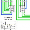
1 pointYou're lights are wired correctly. This is the way they come from the factory. The high/low switch decides which side gets grounded (RW or RB) while the common bulb terminal is fed constant +12 via two fuses. The Dave Irwin relay upgrade harness reverses this situation without issue in a most elegant manner. All is fine, carry on with your day.1 point
-
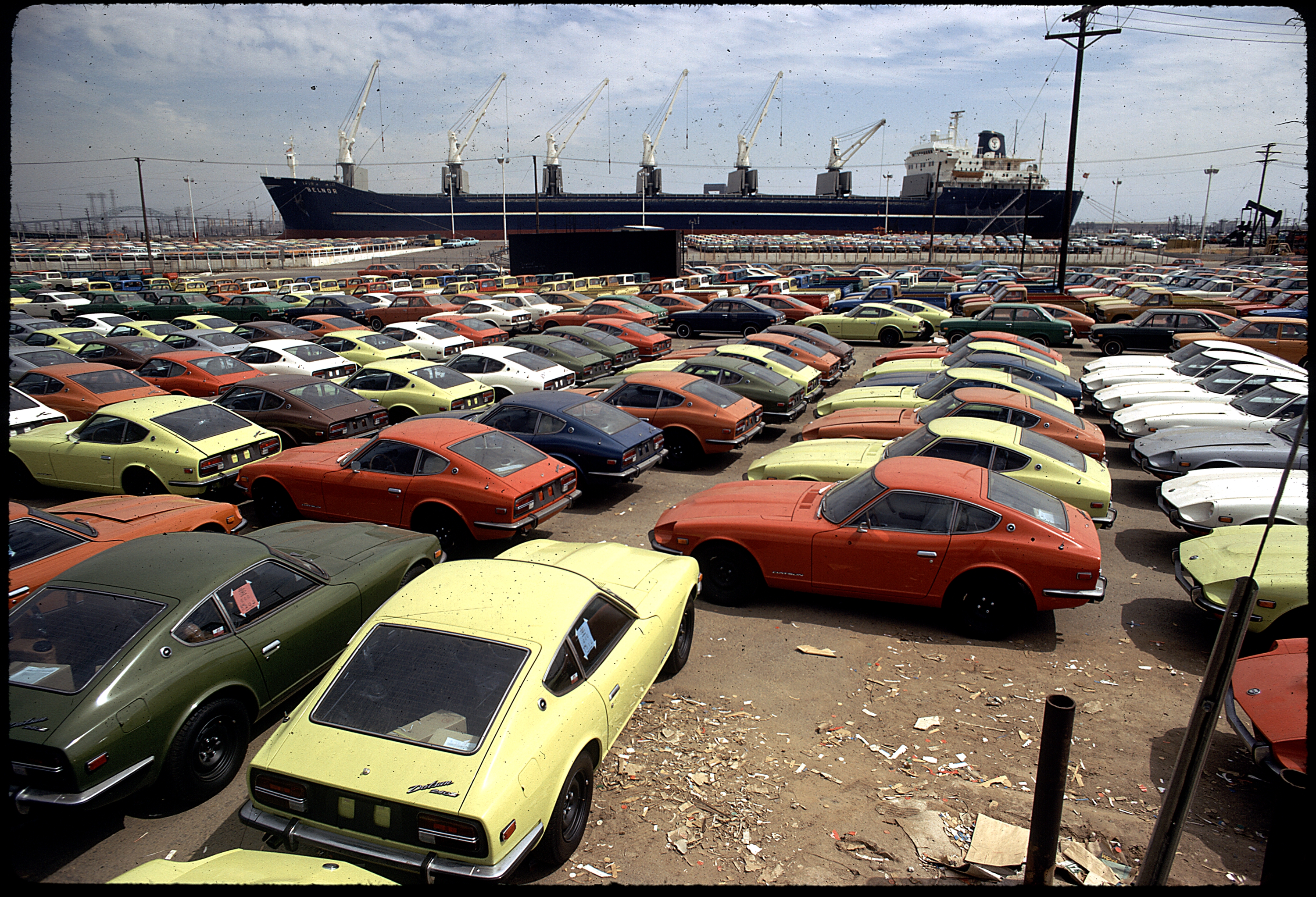
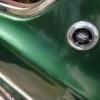
 This picture of Z's at port looks like the same slate/charcoal grey for both the tail light finisher and the license plate lamp when you zoom in, I also agree that they look best being the same color. Here is the full picture, I don't remember who first posted it but thanks to whoever it was.
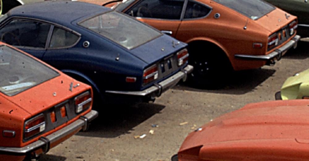
 1 point
 -
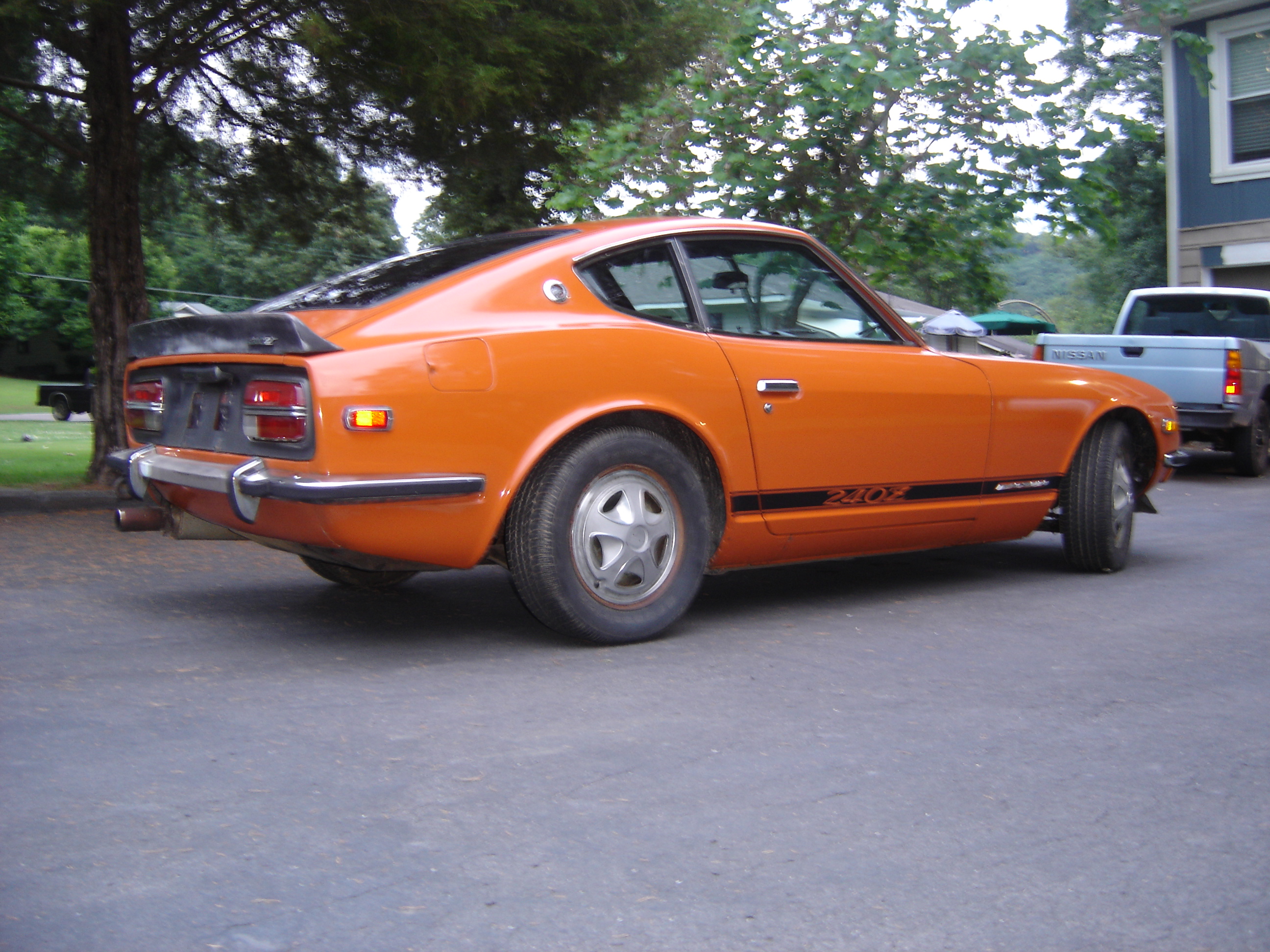
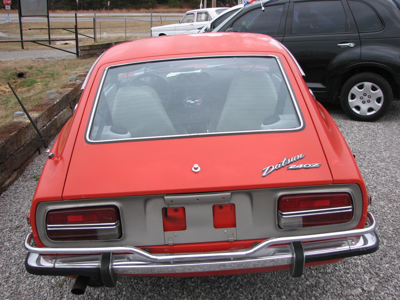
I painted mine back to the graphite color when I bought it. It was painted black as was the finisher. I've always thought the dealership did it when they put the black rocker stripes and the black spoilers on. The reason for thinking that is behind the tag is the only part of the car that's painted black, like they didn't pull the finisher off. Just taped off the lights and stainless strip and sprayed it with no tag. My other 240 is the body color behind the tag, not black. I think that metal is to keep the bulbs from melting the clear lenses, my guess. Here's a picture from the day I got it home. You can see the black where the tag holder is. Here's the other one;

 1 point
 -
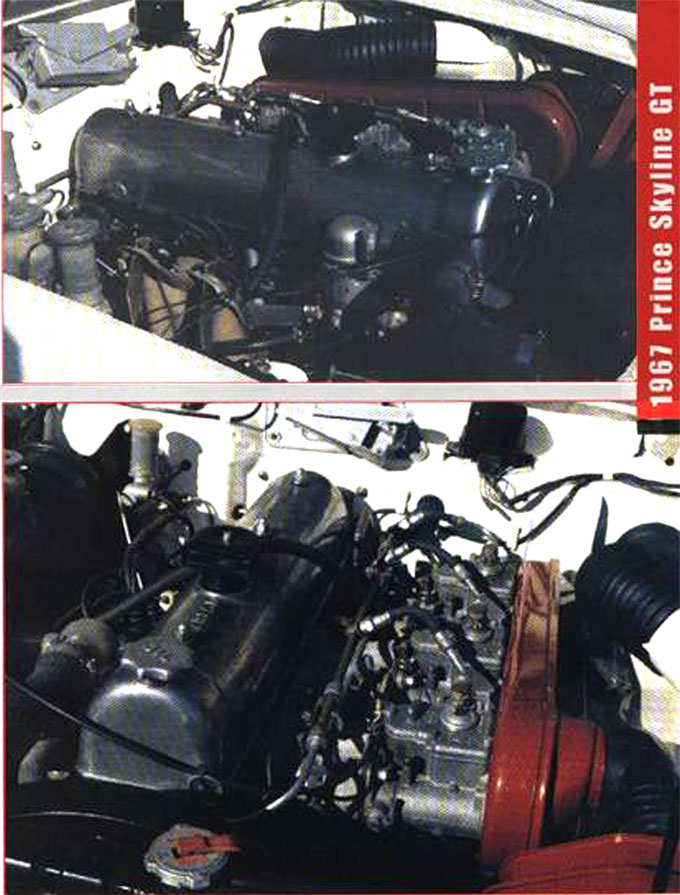
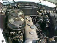
 1 pointHi Will (everyone): Interesting point and based on everything I can find, it would seem to hold some truth. Lets continue the discussion a bit farther... and see if we can find out where the valve covers in question came from..... With the merger of Prince into Nissan starting in 1965 and being completed in early 66, the development of Nissan's racing program and engine development efforts were halted, and the Prince R-380 was advanced. Prince had far more experience in both competition and the design of OHC engines... so why not put it to use. Actually the Prince G7 of 1961 looks amazingly like the Nissan L20 of 1966. (picture below as used in the Skyline 2000 GT A & B from 64 thru 67) Both in turn reflect the M/B engine of the early 50's... with intake/exhaust and spark plugs swapping sides of the engine. One of the first design jobs the engineers from Prince (in addition to the Competition Development efforts), were assigned at Nissan, was the development of the overhead cam & associated head for the 2000 Roadster. The result was a new head with overhead cam, mounted on the older Austin derived block - aka the U20. With twin S.U's a 150HP 2.0L introduced in 67. While all this was happening in 65/66, our friend Mr. K was lobbying Nissan Motors Ltd. for a 1600cc engine in the upcoming 510. As originally spec.'s the 510 was to be a 1300cc, but Mr. K felt that was too small an engine for his US Market. Not getting the support from the management chain in either the Design Department or the Export Department, he felt was critical to the success of the 510 in the Export market, he called on an older friend, whom he had known from MITI and who was then a high ranking Nissan Official... a Memo ordering the 1600cc engine for the 510 was drafted, signed by Mr. Matsumura and sent down the management chain in April 66. (there is a chapter about this in Halberstan's "The Reckoning". - and this is part of Mr. K's troubles with H.Q. over the years) The L16 was thus born in 67 and introduced in the 1968 510. This is the beginning of the "L Series" engines we all know and love today. It was in fact a complete new engine design. new block, new head, new "Valve Cover". One might call it the next generation of Nissan L Series engines at Nissan; where one Parent was Nissan and the other Prince, but it was not otherwise related to their previous "L" Type engines. In 67 when Mr, K ask for an L24 for the Datsun Z, the L16 In-line four, became an L24 In-line six. 1595cc/4=398.75cc x 6 = 2392.5 aka 2393cc. Same bore/stroke, valve train components etc. In effect the L16 with larger valves and two additional cylinders. (this kept parts inventory and mechanical training common to the two engines used in the export market). In this case the L24 might be viewed as simply the Grown Up version of the younger L16. In 68 the Cedric G130 received an L23, which would appear to be a shorter stroke version of the L24. (bore 83/ stroke 69.7). It would be interesting to see what the block casting numbers are on these engines. In 69 the Cedric G130-U received the L24. The L20A that by the end of 1969 was standard in the JDM Fairlady Z's. must have come into being some time after the L24 was specified and design started. Why would I think that??? Mr. Matsuo tells us in his book "Fairlady Z Story", that he had concerns that the L24 specified for the Z (around Aug. of 1967) would meet with very high taxes in Japan, thus resulting in a model too expensive to sell in the domestic market. When he expressed these concerns to Nissan Management, he was told to use the Prince S20 for the JDM market version (this eventually became the famous Z432 model incidentally). So at least we know that in Aug. of 1967 the L24 with both Standard and Automatic transmissions were planned for the Z and that the S20 was specified for the JDM by Nissan Management. The L20A must not have been around at that time - otherwise Mr. Matsuo's concerns about engine size for the JDM market, would not have existed at that point. It would appear that by Oct. 69 the L20A had been conceived, and was already starting production, as it showed up in the spec. sheets, press packages etc. Of course in Oct. of 69 the spec. sheets/ sales brochure outlined an L24 with triple solex side drafts, 10:1 compression and 175HP for the Export Market at that time too. (sad we didn't get it as planned;-( So our L24 Valve Covers are simply streatched versions of the L13/16 valve covers. I think there was an L16 valve cover that said "DATSUN OHC" on it. Maybe I'll try to get one, and have to modified to fit an L24. That would be a conversation piece! FWIW, Carl B. Carl Beck Clearwater, FL USA http://ZHome.com
 1 point