Leaderboard
-

Captain Obvious
Free Member3Points9,849Posts -

SgtAngus
Free Member3Points9Posts -

kats
Free Member3Points2,209Posts -

RIP260Z
Free Member2Points358Posts
Popular Content
Showing content with the highest reputation on 02/24/2020 in Posts
-
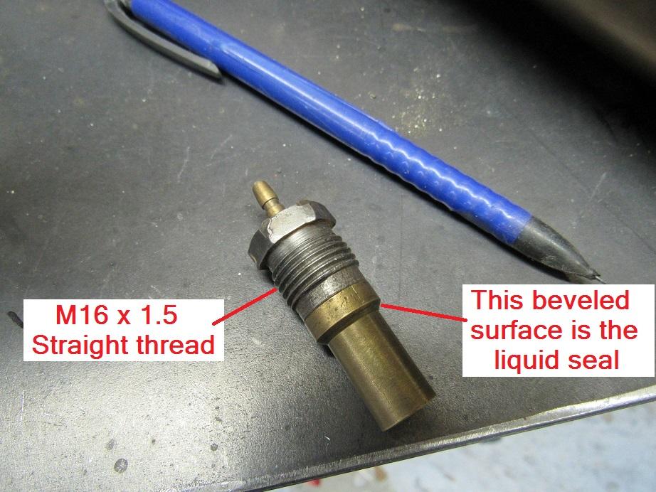
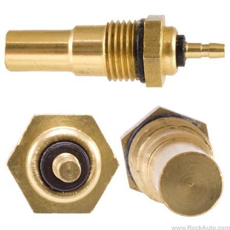
3 pointsAnd although nobody asked (rarely stops me), here's some additional info about those sensors. The original sensors are actually two pieces. A steel threaded portion and a brass sensor portion. The steel part uses a straight thread and the reason they can get away with a straight thread (not tapered) is because that's not what holds back the coolant liquid. The liquid sealing surface actually has nothing to do with the threads. The liquid is sealed by the small beveled edge further down the sensor. Taking liberties with Granny's photo: Some of the newer aftermarket sensors are all one piece brass like the below. Note that the O-ring does not hold back the coolant. All it does is keeps dirt and junk out of the threads. The same beveled surface is what keeps the coolant in:
 3 points
 -
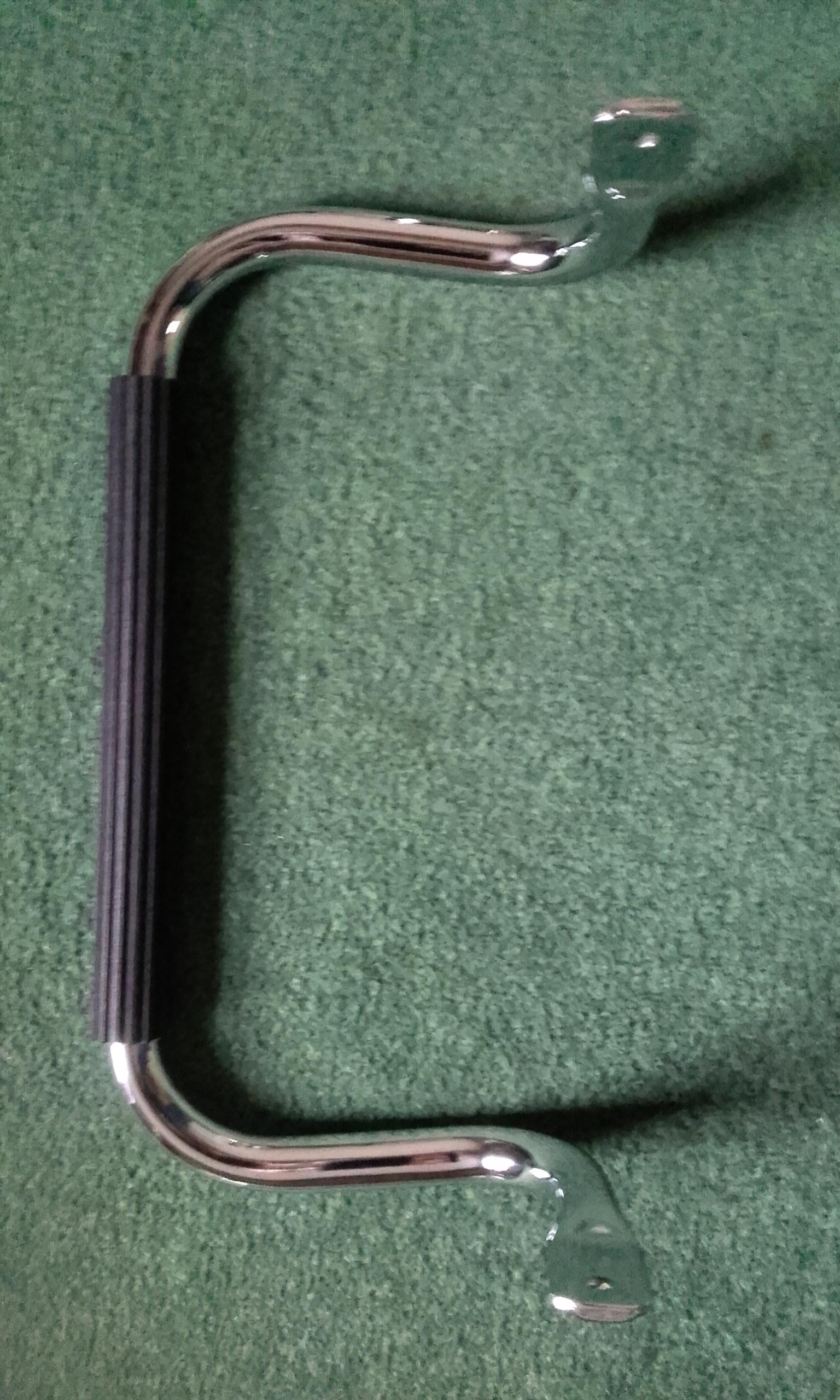
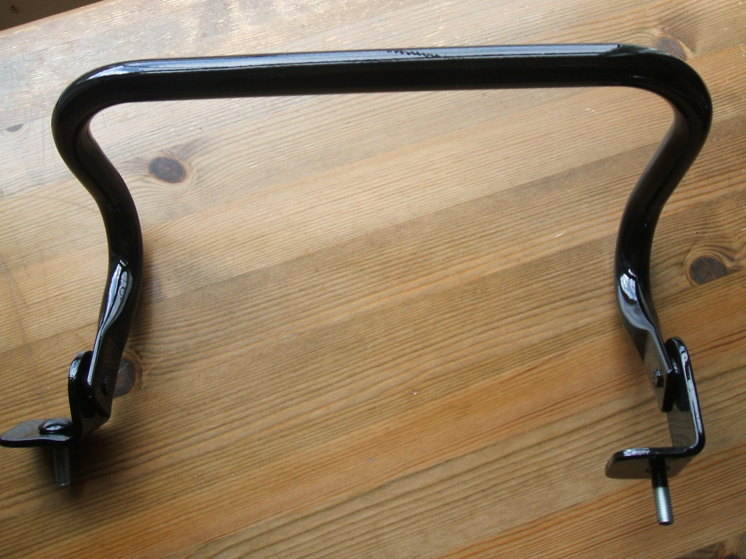
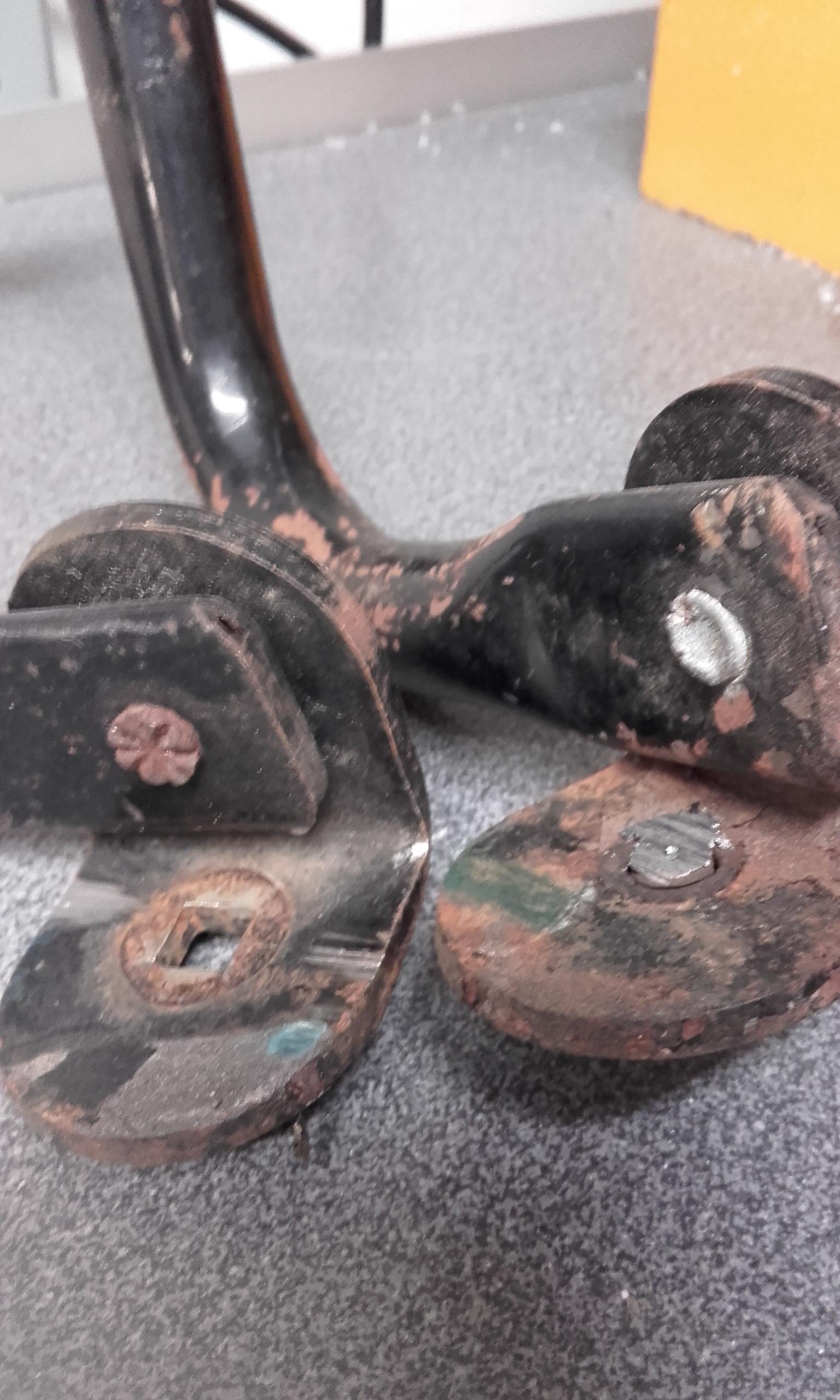
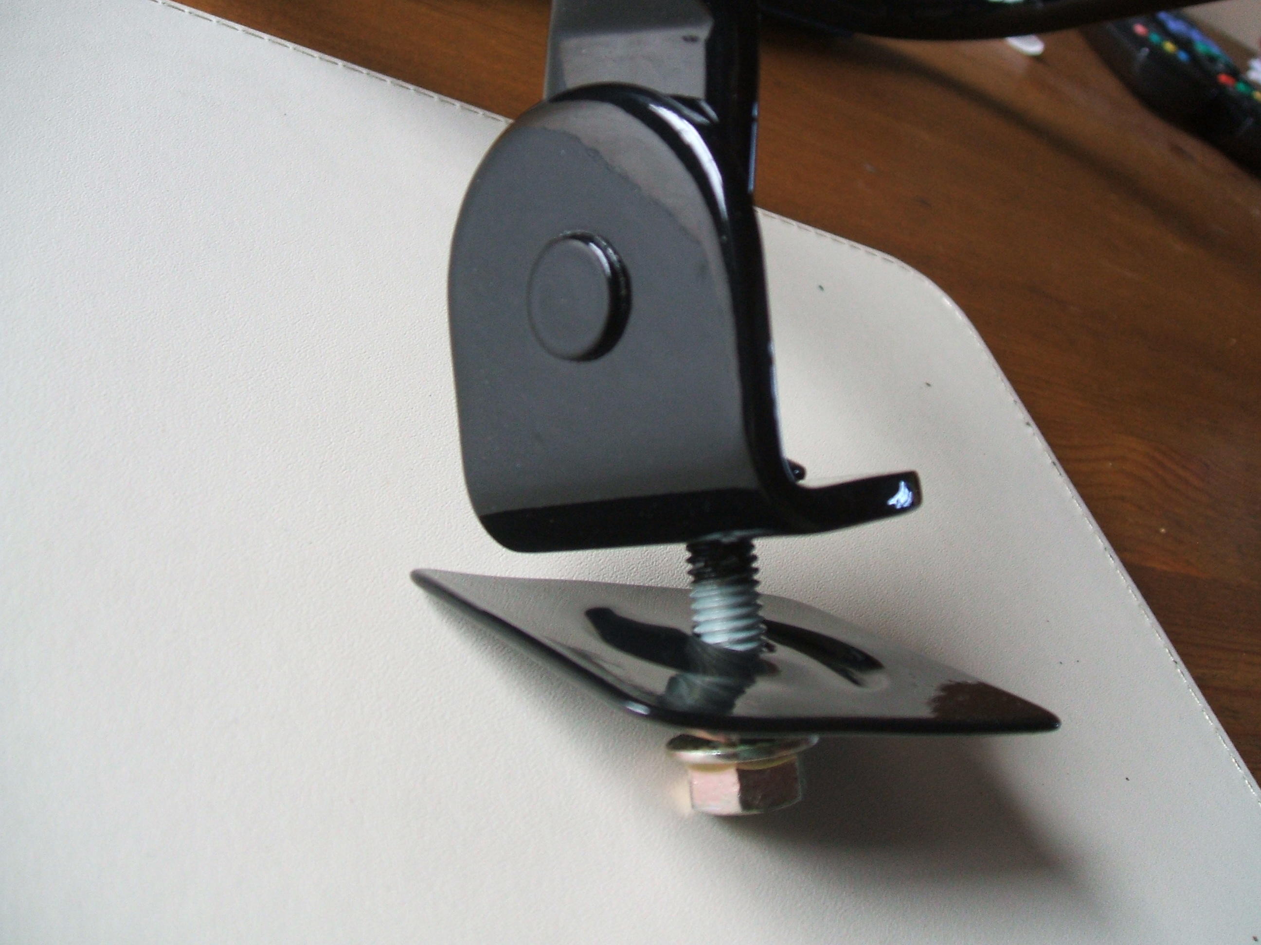
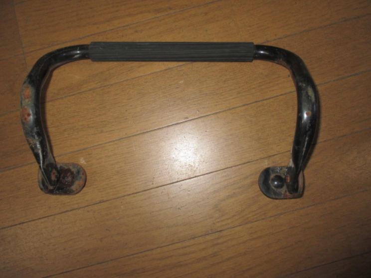
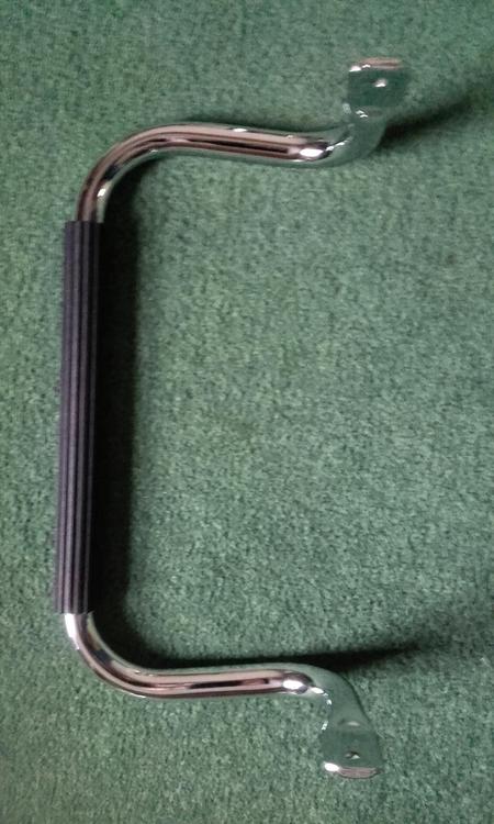
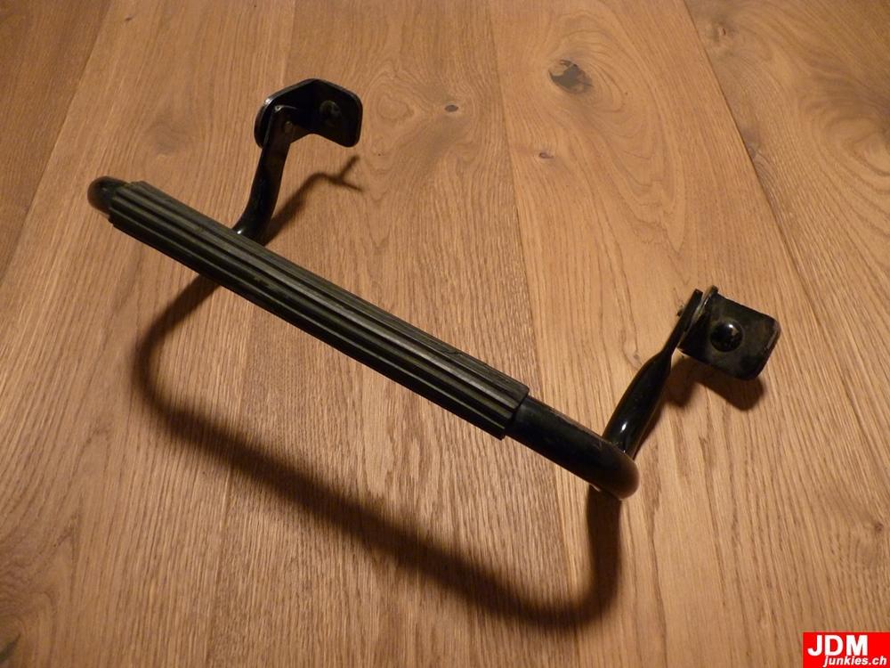
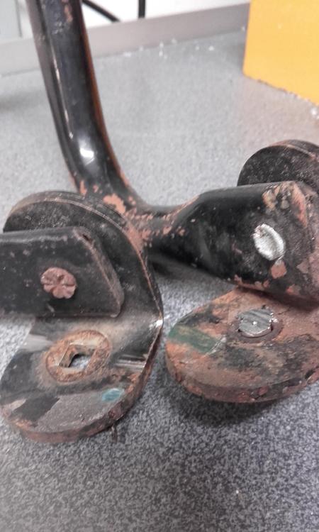
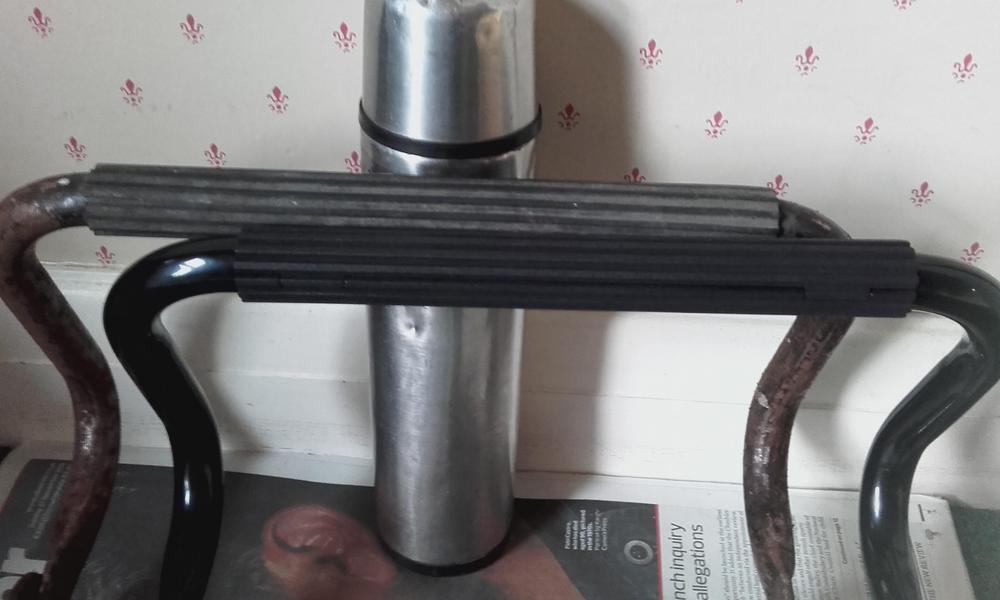
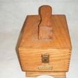
2 pointsAs I mentioned on page 22 of JDM'junkies build thread, I have seen differences with the passenger footrest, which HS30-H says was standard equipment on 'DELUXE' models in Japan, and an extra-cost showroom order option on 'STANDARD' models , within that thread. This is by no means comprehensive, so, please correct, add info. Lets start with a S30 footrest Kats says (in the above thread) is from Fairlady Z from the beginning (Oct 1969 ) to 1973 or later . I think the footest we see on the S30, originates from a preceeding model, the SP311/SR311, as my understanding it was an option from 1967 on, part number 74340-25500. But, the "hoop" part was chrome, with black "feet", and the feet were mounted inside the hoop. Maybe the feet were mounted inside, as the floor pan is narrower. Did this SP/SR footrest make its way onto the prototype/ pre-production S30's or did Nissan go straight to the black painted one? Interested to know. Did the footrest go further back in the Nissan model range? I haven't seen a -25500 one, just a grainy photo, but here is the start of my reproduction one; It's not finished, I have to reproduce the rivets to hold the feet. Anyway, back to the S30 one. Here are some differences, I have no idea how they fit in with models/timescales. The "hoop" shape doesn't really change. It is mainly the feet and how they are fixed. In no particular order; As mentioned in the above thread, JDMjunkies footrest he got, had differing feet ( and for me the rivets say its original, see further down); The feet on the first image from Oct 1969 to 1973, (top of post), has rounded feet, and both feet face inwards. JDMjunkies, has a more square feet, and one foot faces outwards. Which brings me onto this one, The right foot, as you look at the image, is substantially longer than the left, so when mounted the footrest would not be level. Does it mount on a block? It is original, as the rivet holding is correct.The original rivets cannot be removed without destroying them. On all the footests, there is a white/opaque plastic washer/spacer between the hoop and the foot. Which nicely bring me onto rivets. There are two types I have seen, unless replaced by someone with a bolt and nut. The left rivet, has an inside head that is cross hatched, as if its been hit with a chisel/tool to swell the end to hold it. The other side is flat and rounded (see below). The right rivet is aluminium/soft steel, and isn't as strong. I don't have an image of the other side. Maybe going to the right rivet was a production/cost change? The other difference is the bolt that holds the footrest to the passenger floor. On the images above, they have a domed head, with a coachbolt square shoulder below, which lines up witha square hole in the foot. The later (?) type is; A much narrower, taller domed head with a slot in the top. Again, with a square shoulder to line up with the foot, and also a round hole. I am fairly confident this is original, as I have had about 3 footests come my way with this same fitment, and all with the same hoop to foot rivet. Did the footrest came with some specific washers (for under the floor), like the one a couple of images up? The ribbed rubber foot grip is usually ripped on on original un-restored footrest, so finding one intact is good. Sometimes the original rubber grip looks like has been put on in a hurry at production, and can have the ribs running crooked. There is a Nissan part number for this, which is NLA. There is a re-production one on Yahoo auctions, but it doesn't look right. Yes, you could use some ribbed floor matting, but the finding the correct ribs, and then they look wrong as they are designed to lay flat. Not round a metal bar of a tight radius. The effect is the ribs are too splayed. So, I had to reproduce my own, 3D printed, so it looks correct. Original behind, reproduction in front. I hope that gives some an insight to the footrest. Cheers Ian


 2 points
 -
 2 pointsSo for future reference here’s what a ZX and Z oil pick-up tube look like side by side. Approximately 1.5” longer on the ZX one. Oil pan going on today. Sent from my iPhone using Tapatalk2 points
 -
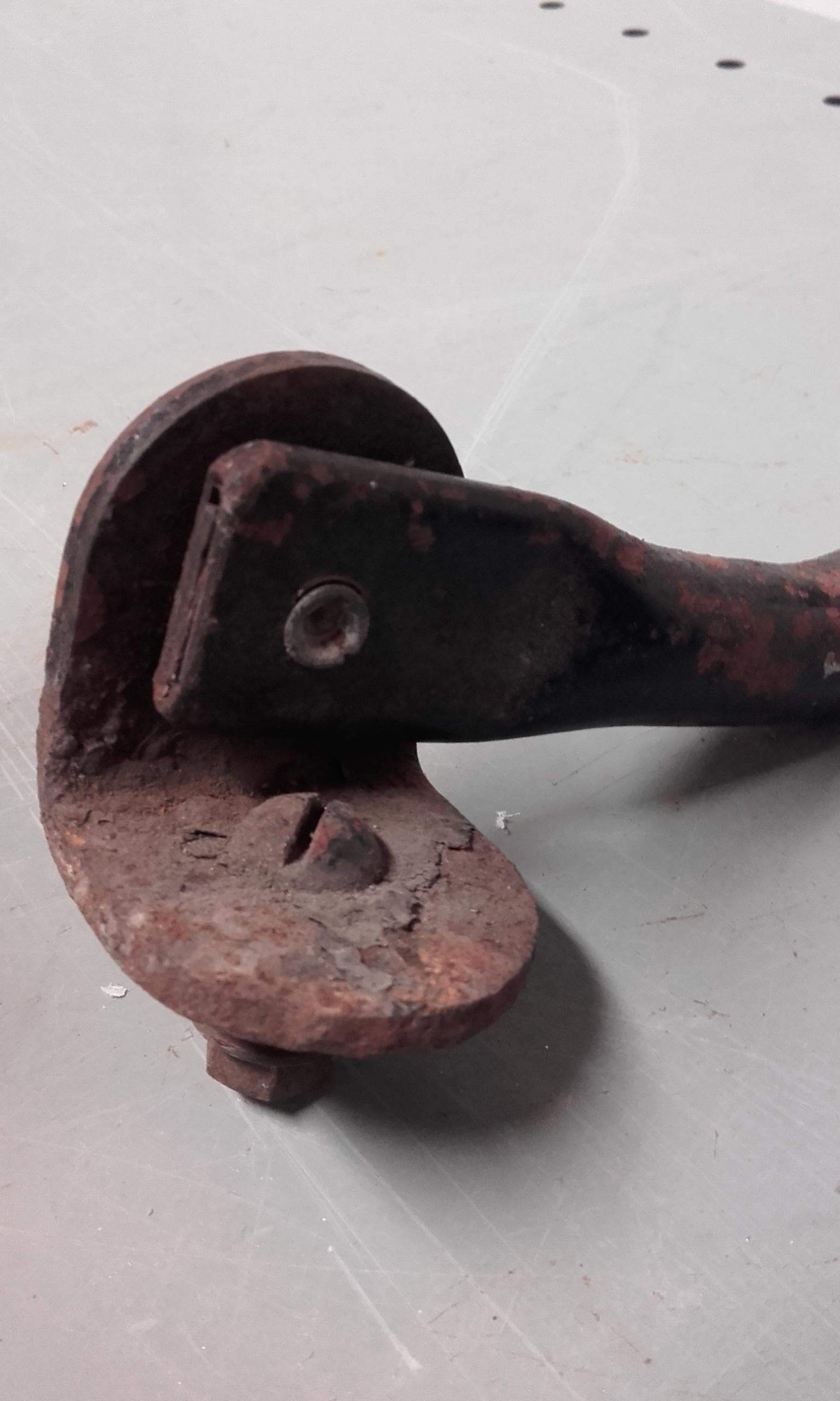
 I really think if your nut threads on just fine, there is no reason to not reuse it. To ensure the staked section ends up in a new spot, make a thin spacer from some brass or thin steel stock. I’ve got a method of releasing the original stake without harming the metal or breaking it. The nut metal is surprisingly soft. In fact I have been successful twice now by simply undoing the nut WITHOUT doing ANYTHING to remove or push up the staked part of the nut! It just gets pushed up as it engages the threads. That 2 ft long 1-1/2 wrench makes it easy to twist that sucker right off. Of course you’re all cringing, “how dare you risk buggering up the precious threads on the shaft, you monster!” But in every case so far, there has been 0 effect on the threads. The shaft/thread metal is about 15 times (professional estimate...) harder than the nut. Then when I put the nut back on and torque it down, I just re-stake in the same spot. Yes after a couple of these I’m sure the staked area will fatigue and break out. Then do the spacer thing to move the stake location. Regarding the reverse switch, Every one I’ve ever taken out hasn’t had an oring or copper crush ring, and new ones I’ve purchased don’t come with them, including Nissan ones. Just clean it and the case where it seats and snug it down. If it leaks, use a thin crush aluminum or copper washer crush washer or a dab of gasket maker goo. Don’t add too much thickness or you may cause the switch tip to not contact the shift rod and render it intermittent or inoperable.2 points
 -
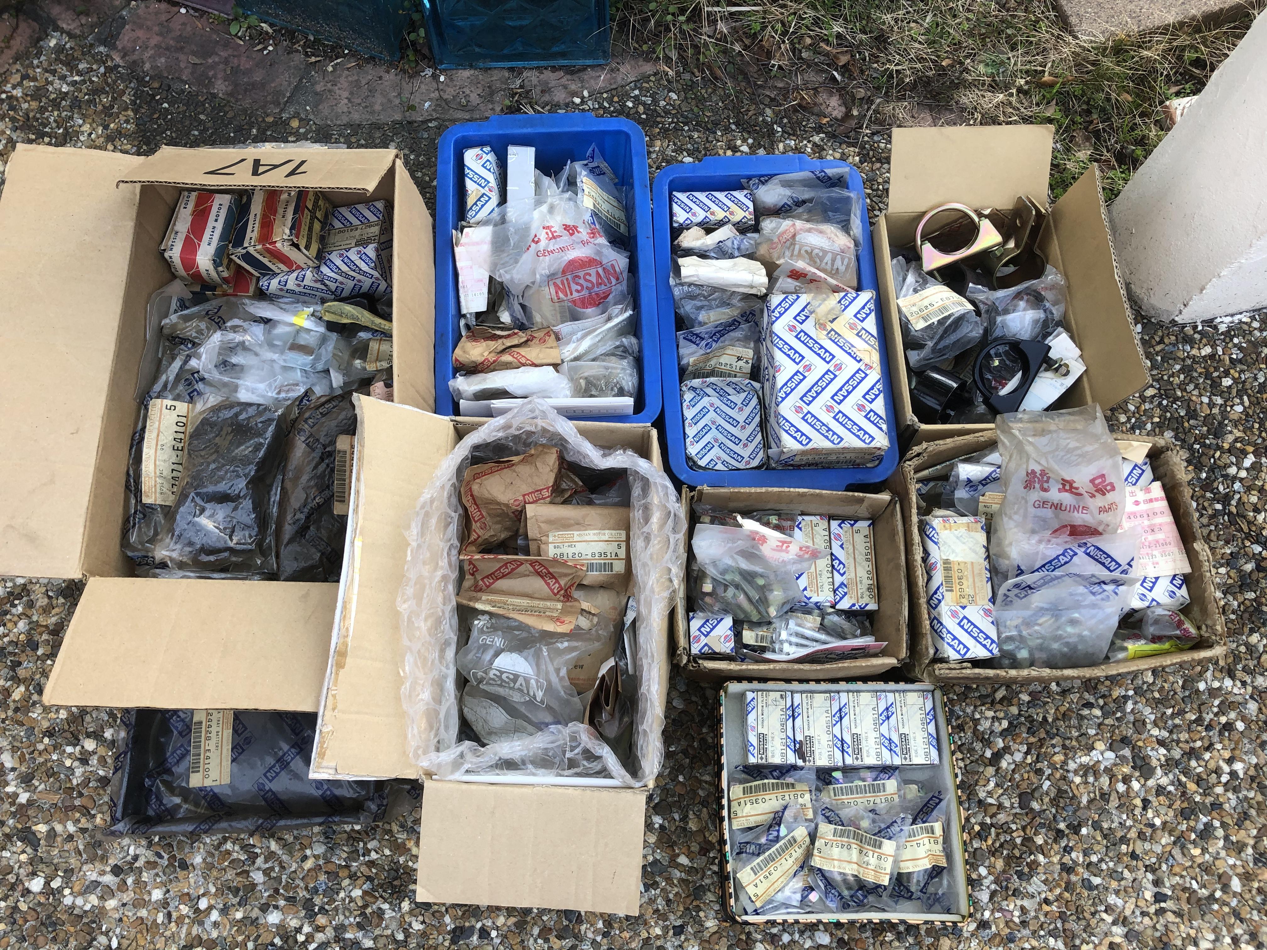
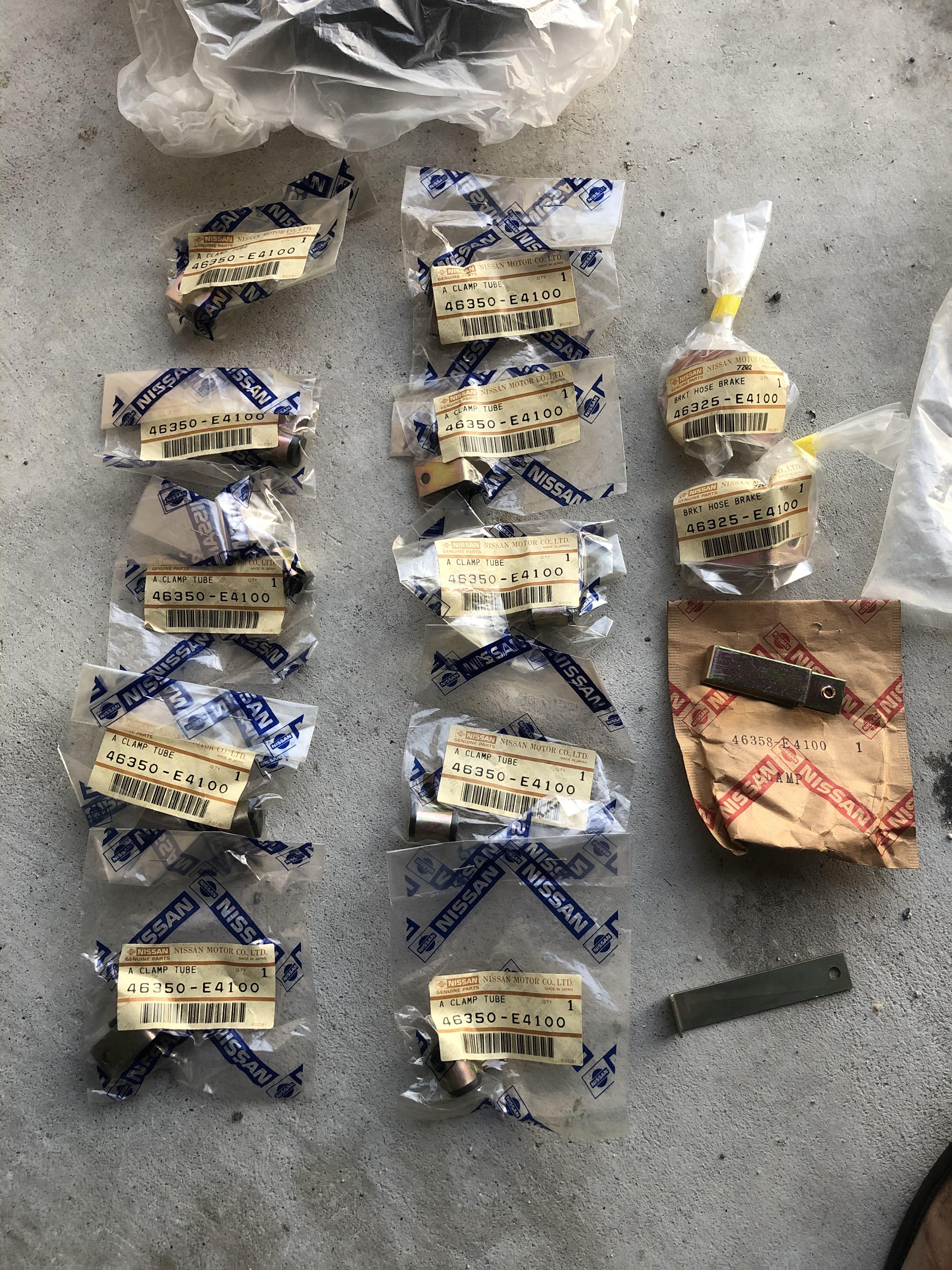
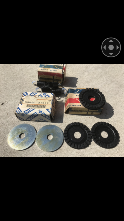
Hi , I hope you enjoy the ride , and the restoration for your 1970 car . I am sure you can get a lot of advices here and you can search everything you need . I recommend when you go through the suspensions, do the drive train i.e . the propeller shaft and the two drive shafts , the diff mount insulators , hubs , brakes etc . If the shocks and coil springs are new but the drive shafts and the propeller shaft are not restored , you will not be happy with your car when you driving it . The engine , the transmission, and the diff are need to work properly of course but that would be next time as I see your car is now in a very good condition. It is fun to order bolts and nuts to the Nissan local dealer ,I hope you can get most of them . Use correct fasteners are very important especially the places where need to be correct tightening torque. It is OK to re- use old bolts and nuts but new ones are always better . And it is beautiful , and you will be highly rewarded for sure . Kats


 2 points
 -
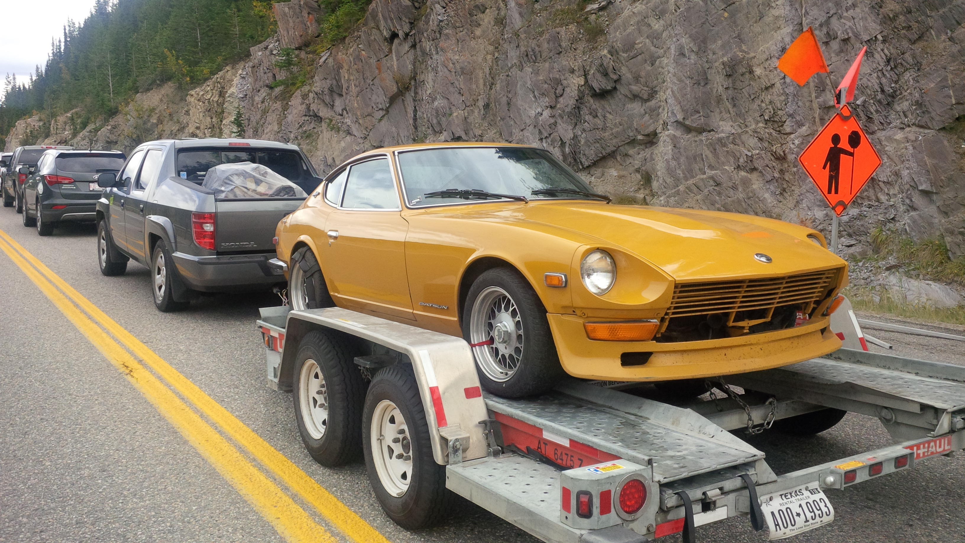
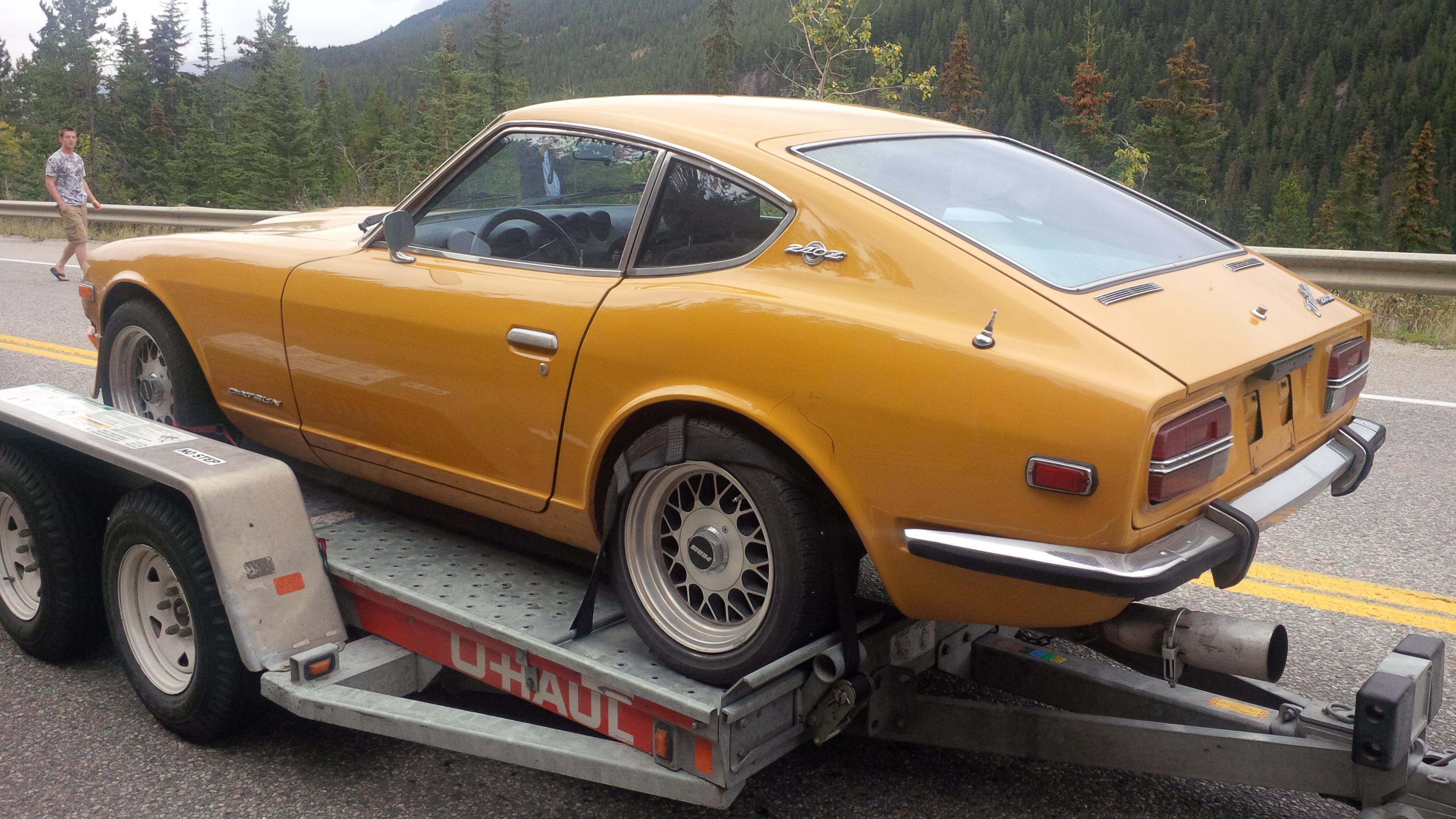
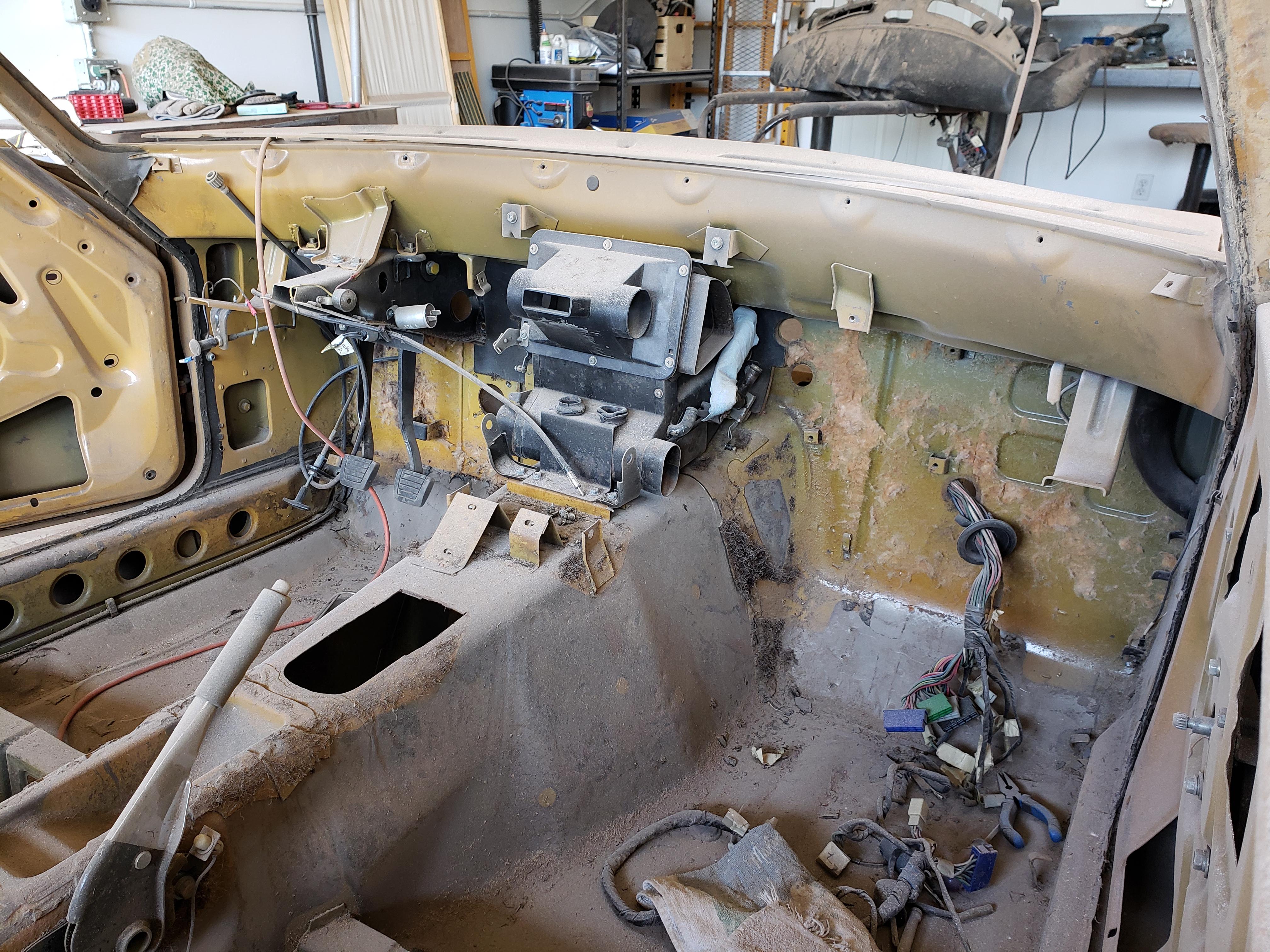
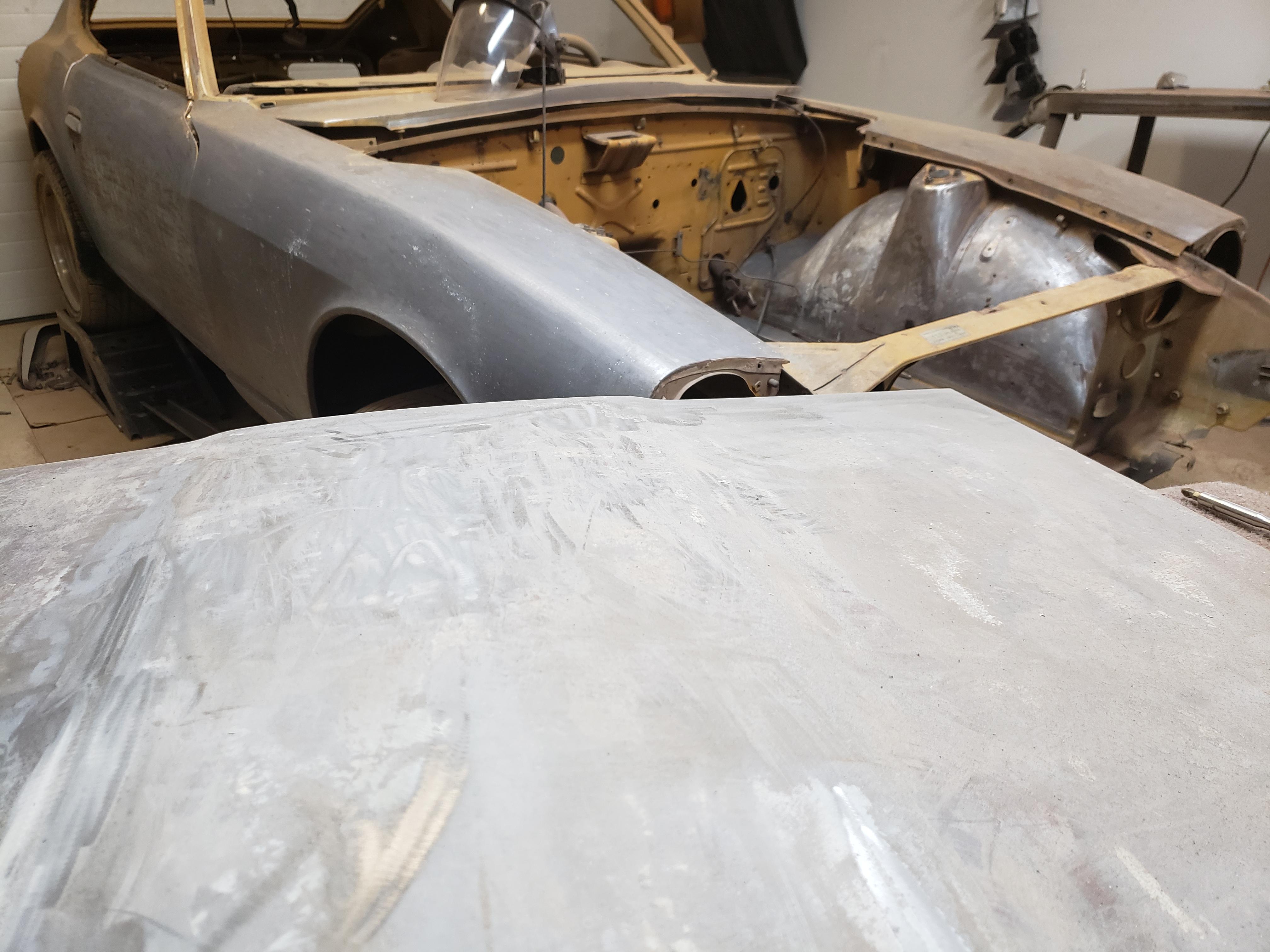
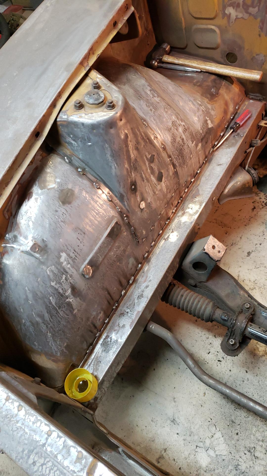
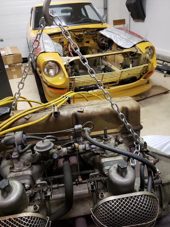
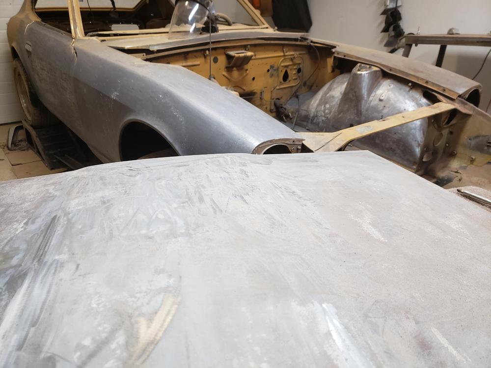
1 pointHello, As a number of folks have asked about my car in my 5 speed for sale thread I thought I'd start a little build thread. A little over six years ago I found the car in Smithers, B.C. and arranged to buy it. The seller has accumulated a bunch of spares for it as he had been storing it in his garage for a number of years waiting for his son to get old enough to restore the car together. Unfortunately, his son did not care for cars at all- bad for Dad, good for me. Having shipped the spares pallet, he drove HLS30-10714 3 hours to Prince George and met me there. We did the deal and I brought the trove home to Calgary, where I lived at the time. Note the classy exhaust extender he used to keep from gassing himself on the drive there... I got it home and covered it for a few years as work was all consuming and I wasn't ready to begin the project. We moved to Dunmore and got a bigger garage in the bargain. I made good use of the exhaust extender and drove it 3 more hours on the highway to our new place. Painful with a 4 speed and stock engine! Once there, the Datsun moved inside and a year or so later the project began. First up was pulling the drivetrain. Then came removal of everything else and lots of labelling. Then stripping the whole car to bare metal. A little paint stripper, and a lot of paint stripping wheels! After spraying the bare metal with Ospho, I began stitch welding the unibody. The battery tray was in mint condition but as I'm placing the battery in back I removed the tray with a spot weld cutter. Anybody need a clean '71 battery tray? While doing the engine compartment stitch welding I cleaned up the fender wells and firewall. The engine compartment welding is now done and this weekend I got a good start on the interior reinforcements. Got the passenger side floor, seat mounts, and rear bulkhead completed. Also added a pair of stylistic elements to the rear bulkhead.


 1 point
 -
 Maybe this?? Not sure if they are still available but worth looking into. A better Auxilary Air Regulator - Fuel Injection - The Classic ...1 point
 -
 1 pointI have seen new style injectors sold as a replacement, IIRC something with 4 hole heads, short tails that have been modified to work with reg hose, and they are designed to not use the resistors to drop current flow due to different coils. sounds like a lot of differences from the recommended replacements. I wonder if the lower pressures would effect them as well?1 point
 -
 Ah, ok gotcha. I thought the reverse checking assembly was datsun speak for the reverse switch. Thanks1 point
 -
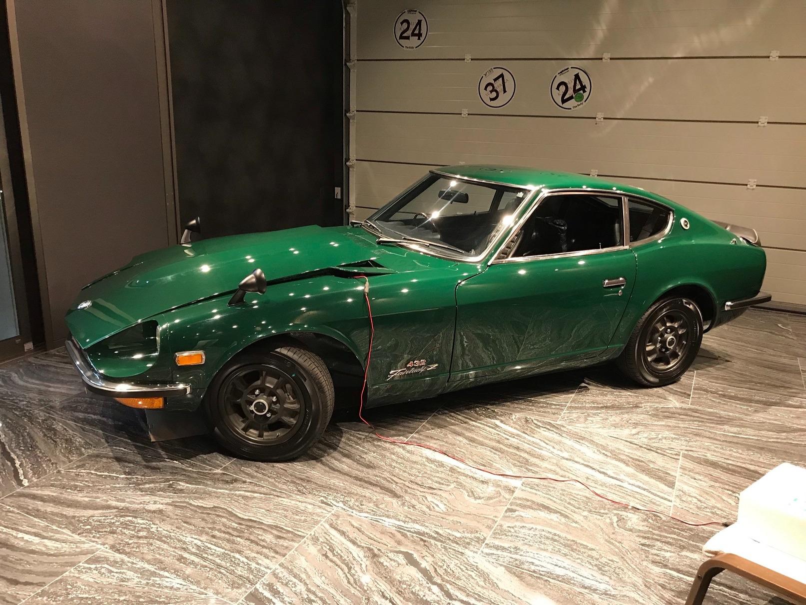
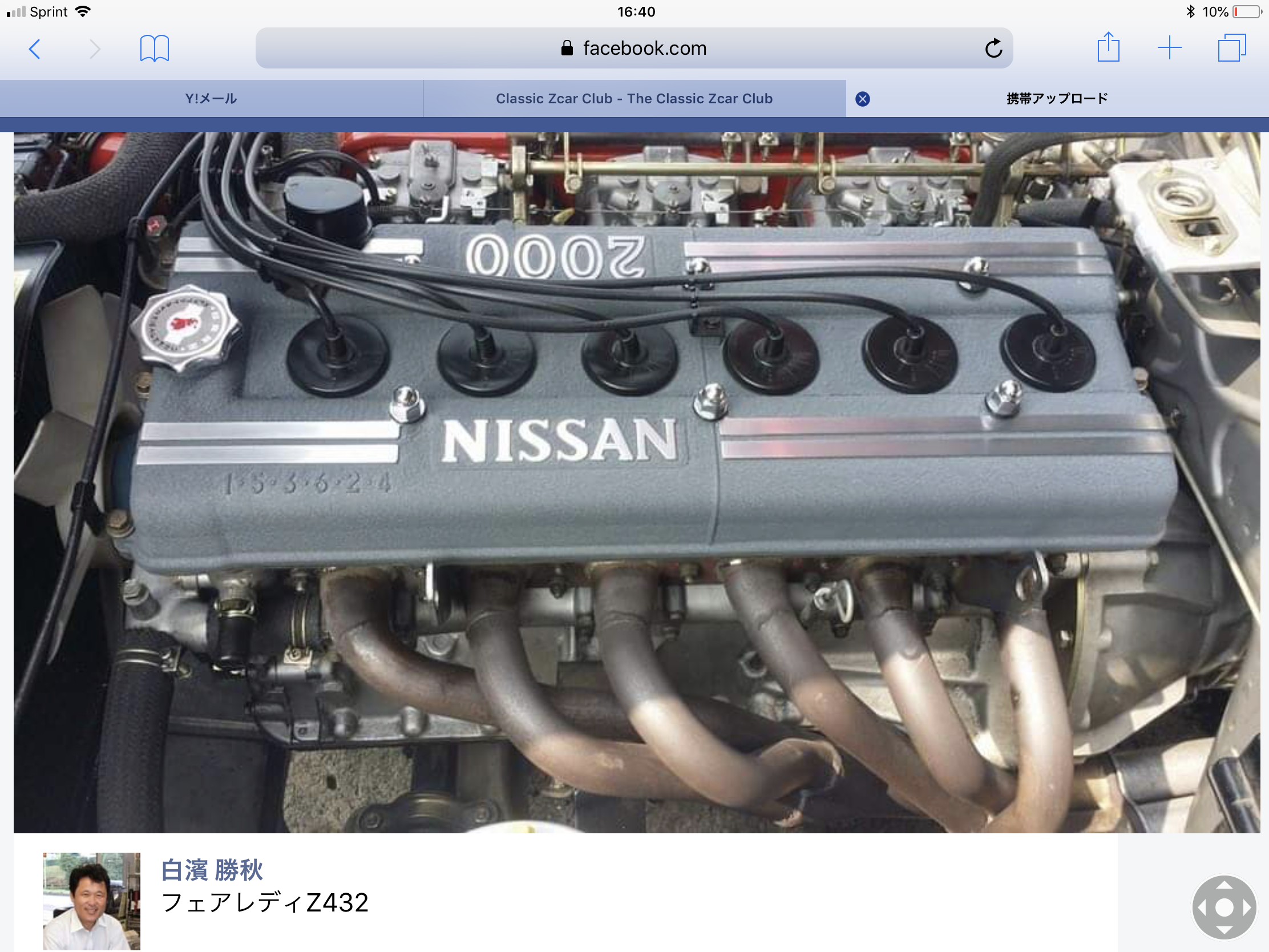
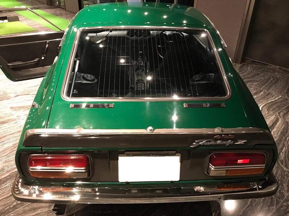
1 pointHi , the green Z432 was ( still is ? ) for sale at 2150 0000 JPY when I heard about it . Lack of some original parts , and need to have proper size tires for stock appearances . Kats


 1 point
 -
Thanks, it looks a lot different than that now. At Wheee's recommendation I started a build thread: https://www.classiczcars.com/forums/topic/63609-71-240z-project/1 point
-
 1 point
 -
Hello! Thanks for the welcome. I work in Calgary and commute from Dunmore every week. My '71 240z #10714 is a very clean original California car imported to Canada by the fellow who sold it to me. I found it on Trader in Smithers BC. The owner drove it three hours to Prince George to meet me and had shipped his spares pallet by FedEx to give to me. I bought it on sight. Got the pallet loaded into my truck at the freight depot and brought the car to Calgary on a trailer (see pic). He had it in the garage for 7 years waiting for his son to be old enough to restore it with him. Turns out his son didn't care for cars. Bad for Dad, good for me. Later on I drove it to the Hat and began the build. Painful drive with the stock engine and a 4 speed! It has solid floors, battery tray and spare tire well but rust in the bottom of the dog legs. Stripping the whole car by hand revealed one repaint and minor fender benders on the DS quarter and PS front fender where the panels had some bondo over a small repair. It had the original driveline. I've been working on it for 18 months but as I"m out of town during the week it goes slowly.
 1 point
 -
 1 point
 -
 1 point
 -
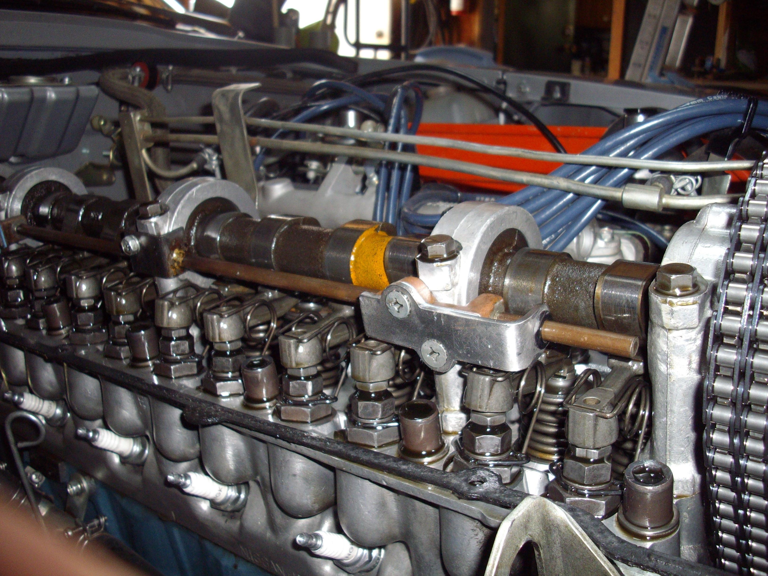
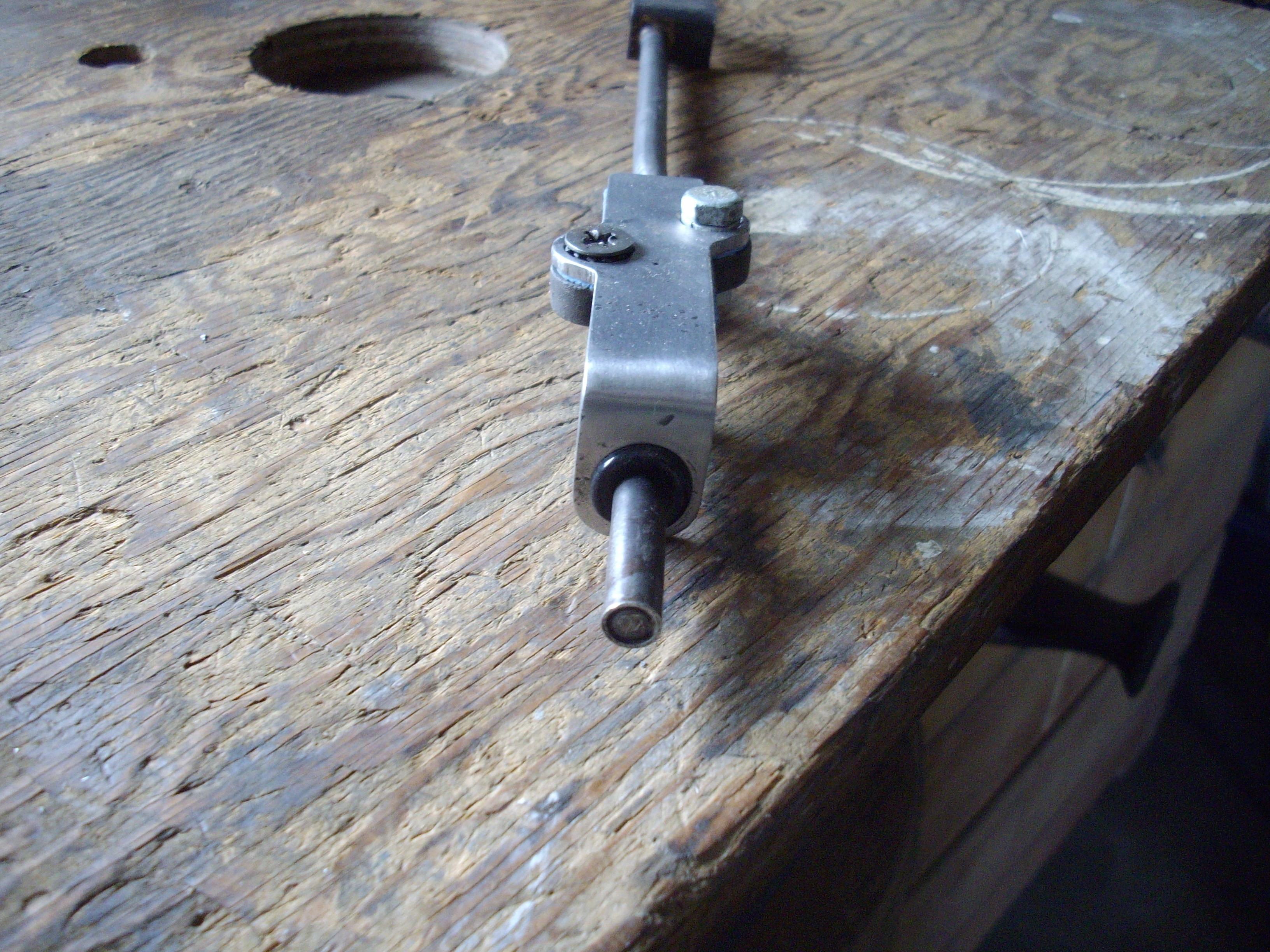
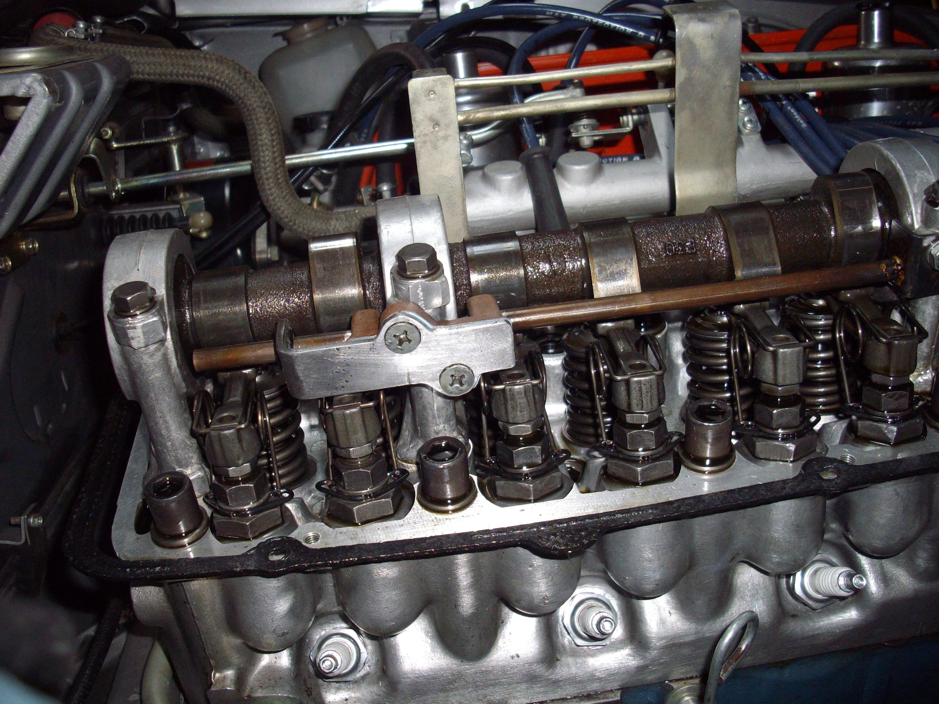
 1 pointSo after seeing what happened to my cam oiler tube, and talking to another Z owner who had the same problem with major results. The front tube fell out and got caught in the timing chain. Trashed the bottom gear and of course bent a bunch of valves. So I decided to try to come up with a way to stop the tubes from fall down into the lower engine if they failed and am trying this to see it helps.

 1 point
 -
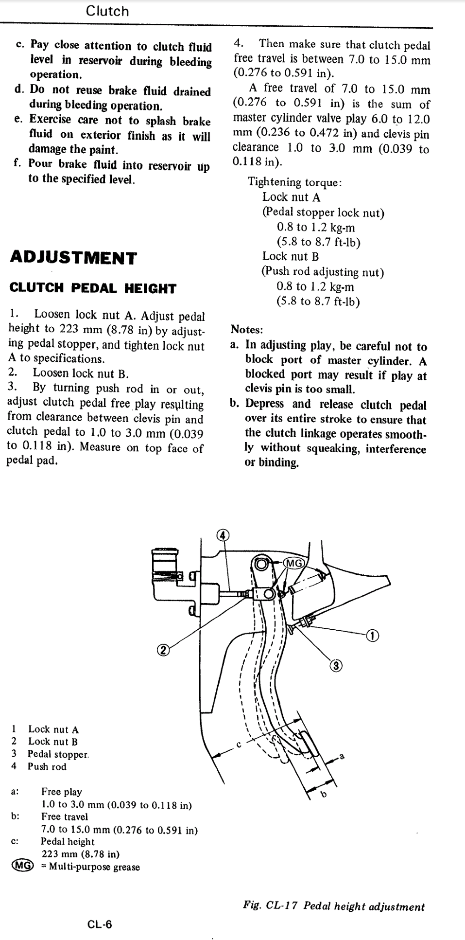
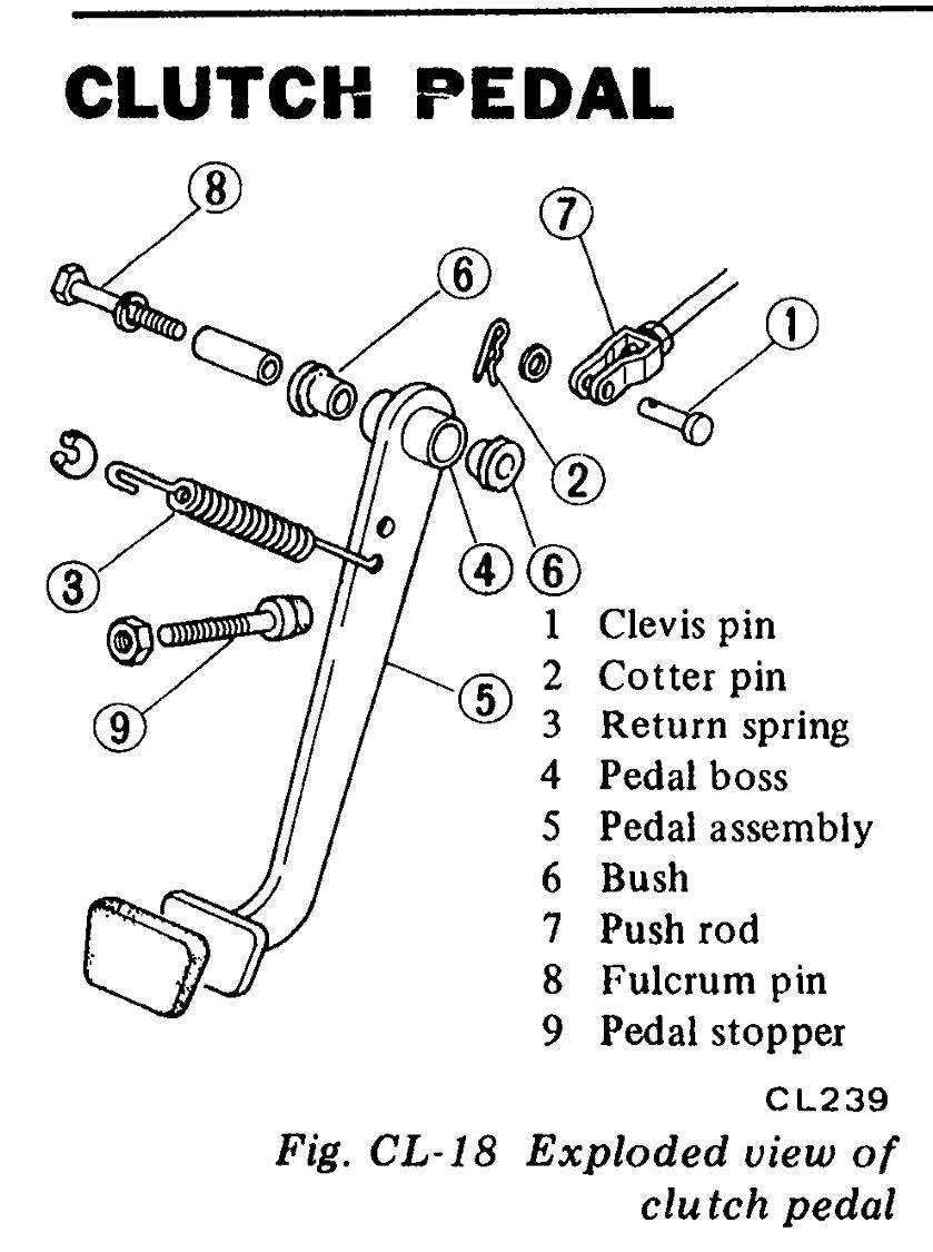
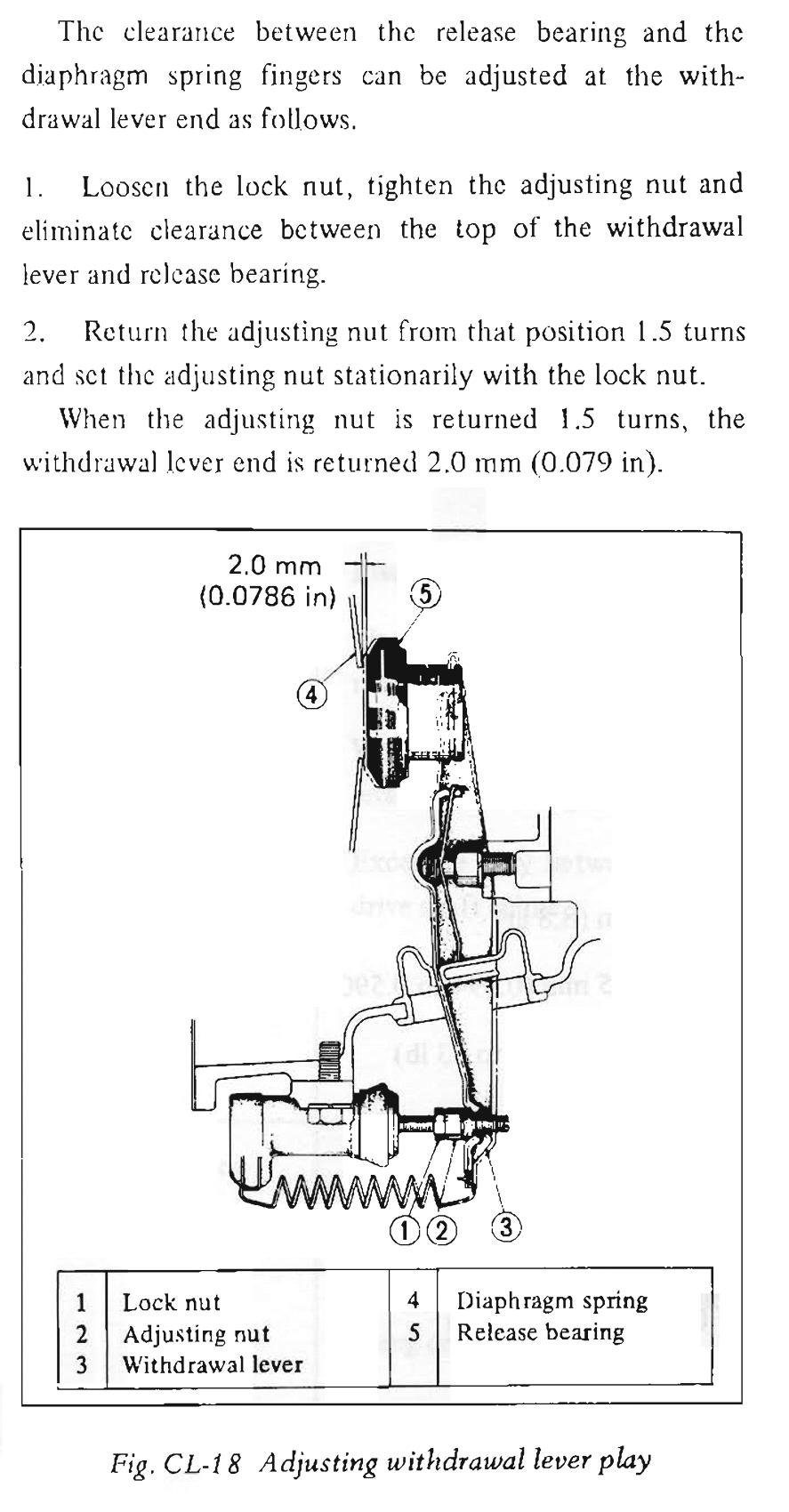
 1 pointI have not seen any measurements fro the pedal adjustment. Did you follow the procedure in the manual for adjusting the pedal and slave cylindrr rod? Don't assume. Do the checks and tick of the list. A blocked port in the master cylinder or insufficient pedal travel can cause a lot of hartache. Push the pedal to the floor and note where it touches. Measure from that point. I made some screenshots of the 72 FSM for the slave cylinder and the 77 FSM for the pedal adjustment. I find it a little clearer. Though it helped (me) to read it twice?.

 1 point