


Leaderboard
-

7tooZ
Free Member8Points1,038Posts -

siteunseen
Free Member6Points15,089Posts -
Captain Obvious
Free Member4Points10,063Posts -
AK260
Free Member4Points999Posts


Popular Content
Showing content with the highest reputation on 10/07/2020 in all areas
-
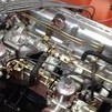
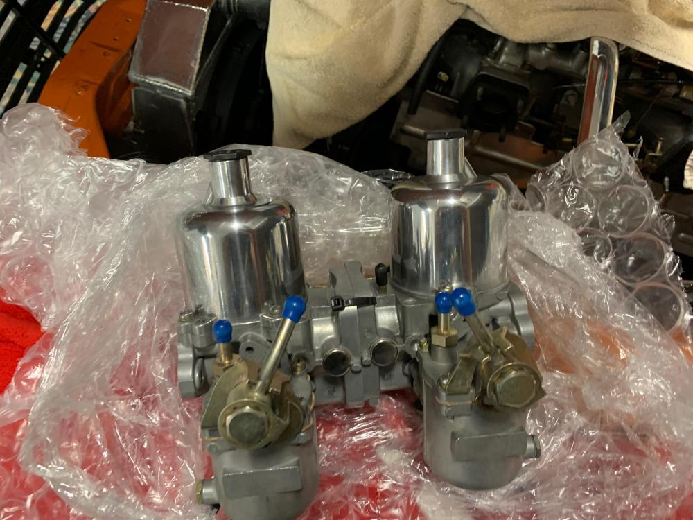
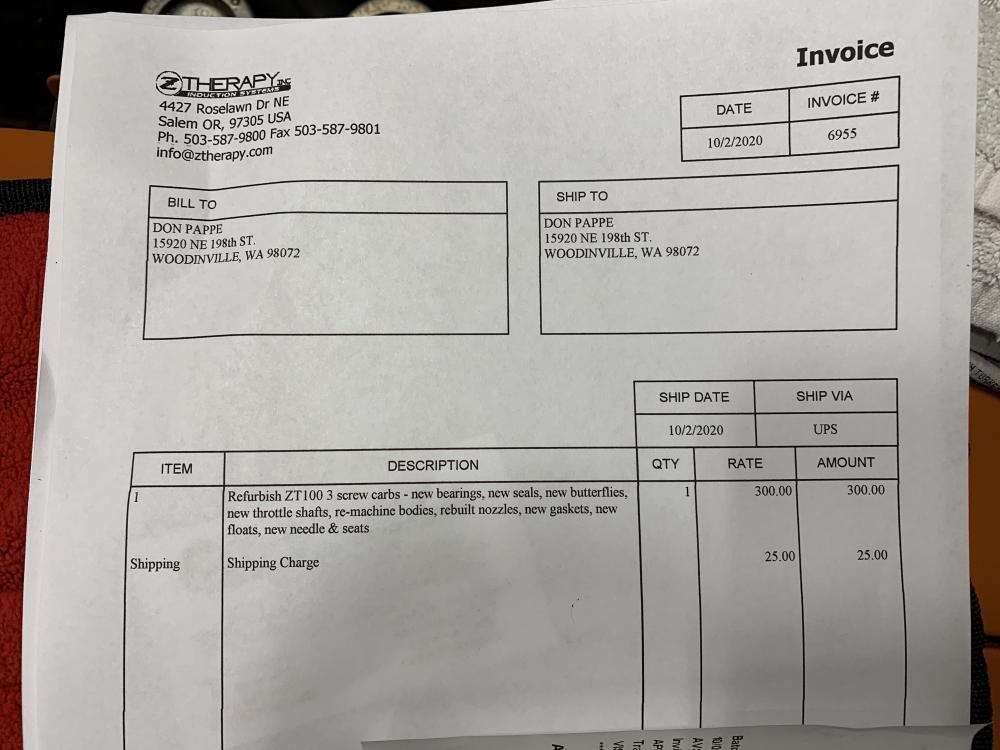
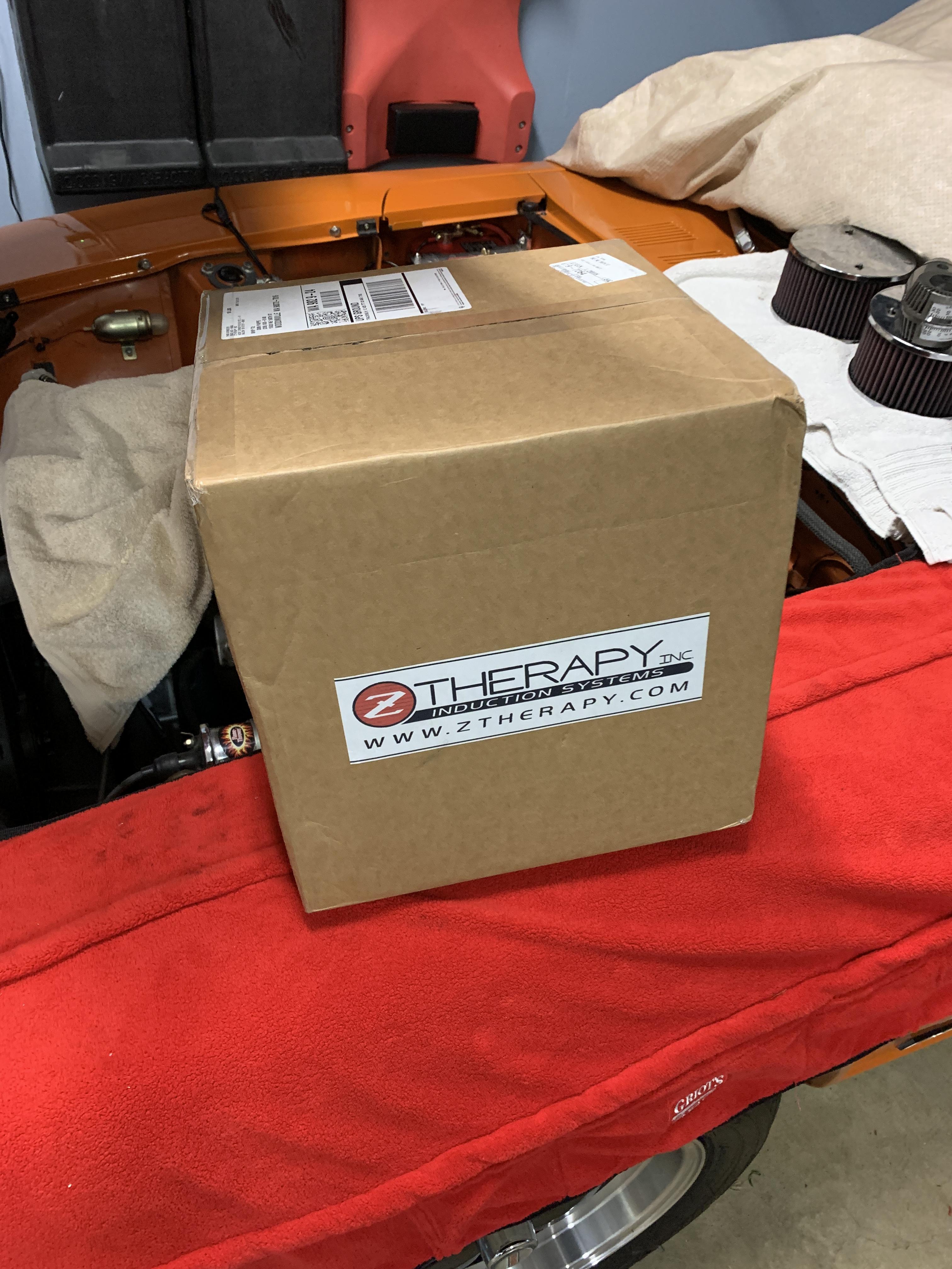
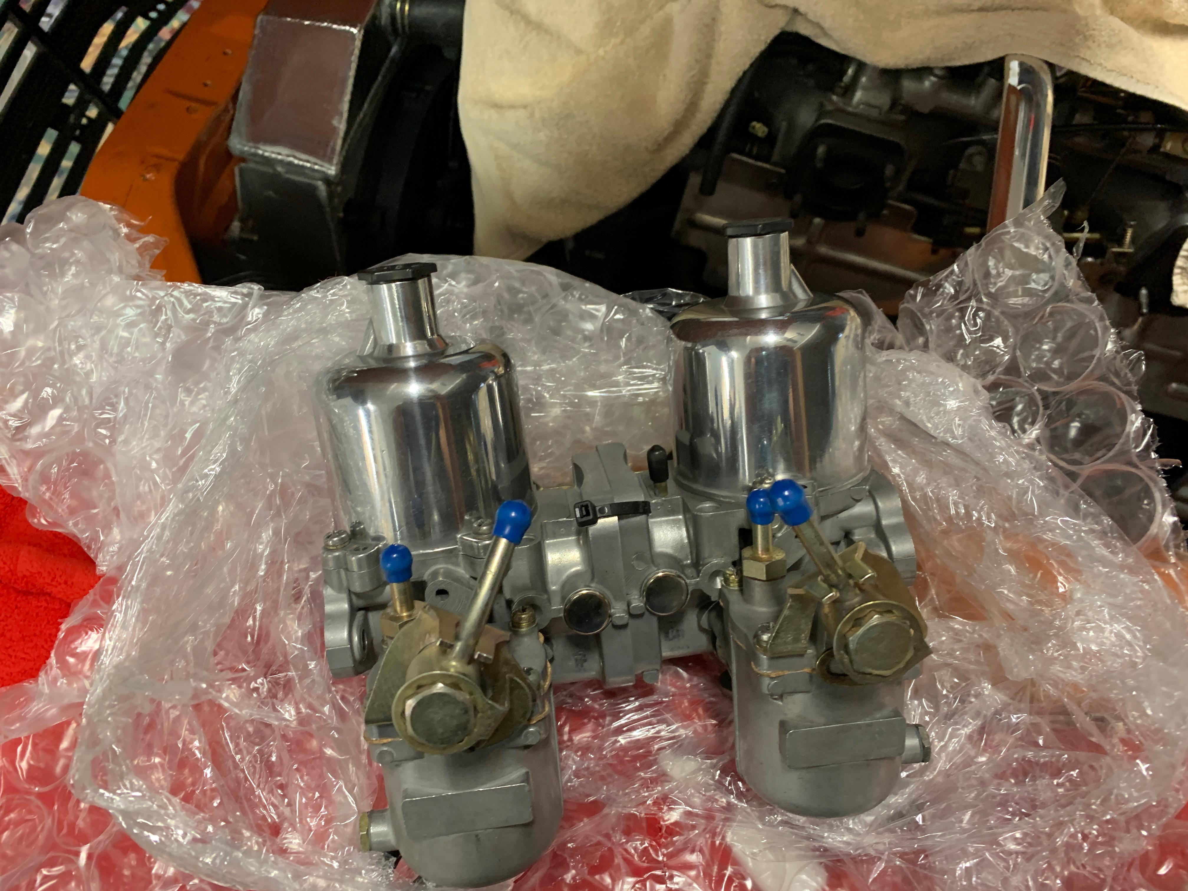
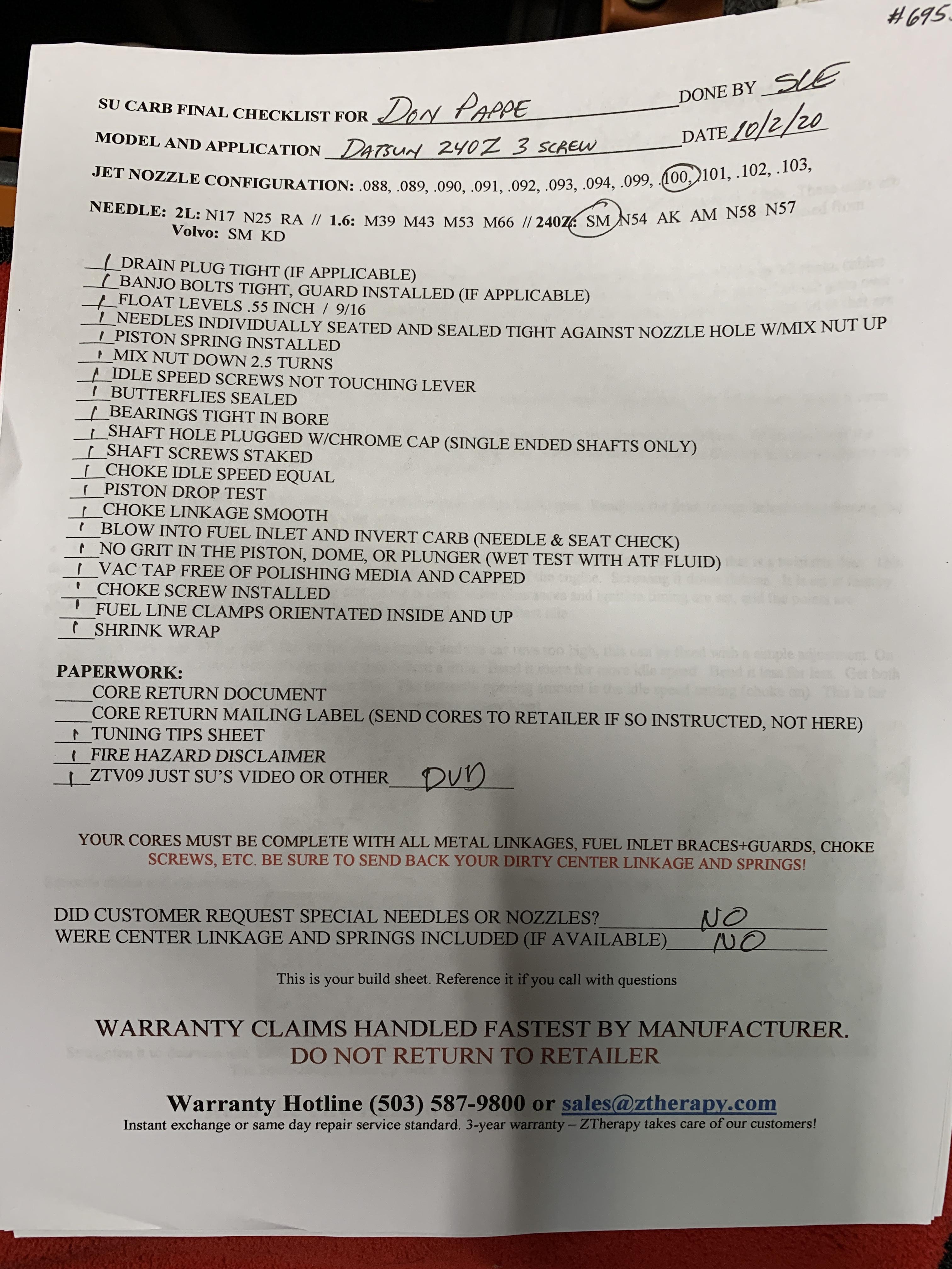
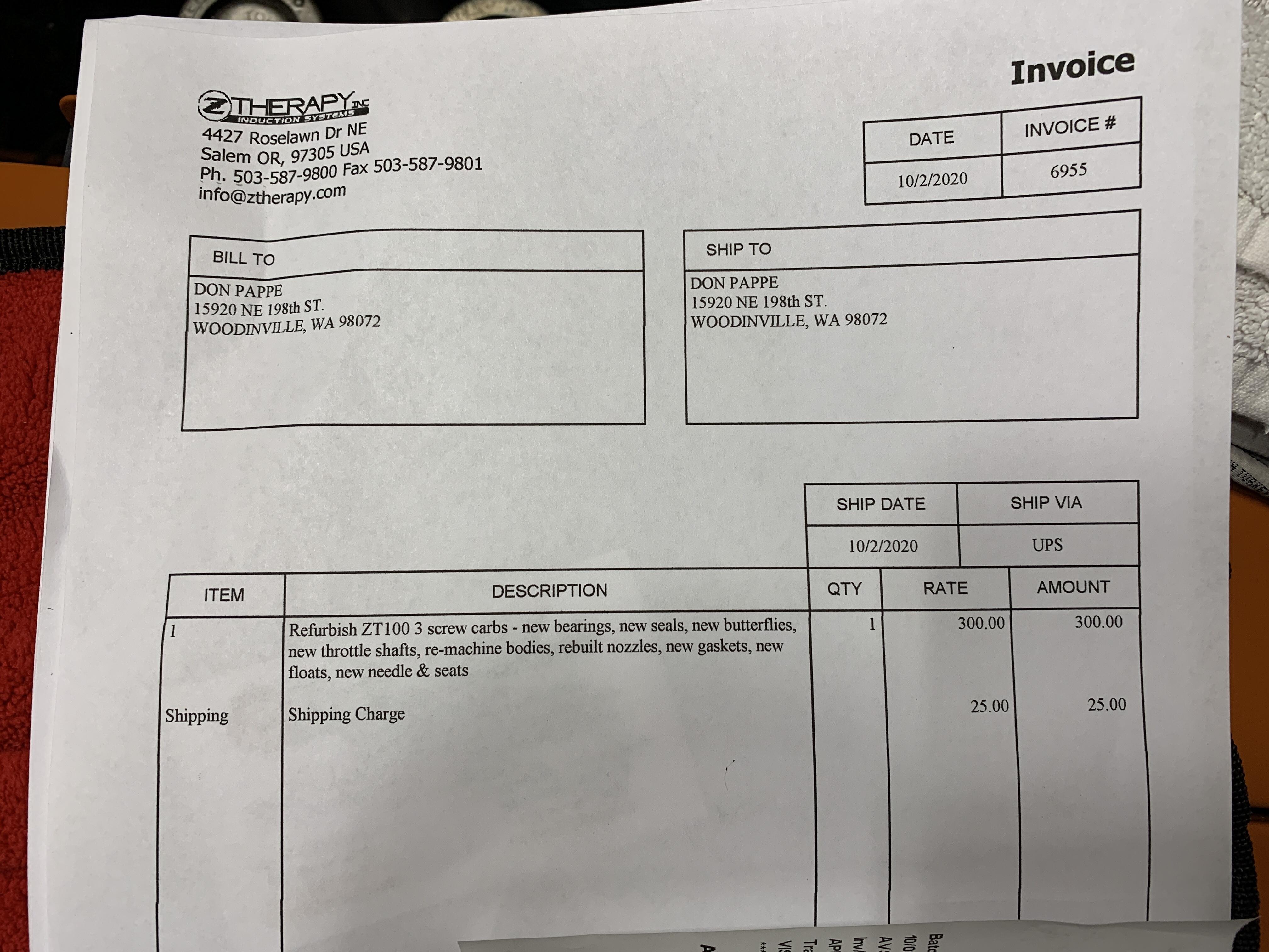
8 pointsReceived a package today with a couple gems inside. For the last month or so I have been chasing a lean condition just off idle on my 240 motor. Cold it was hard to start even while being choked, a condition I have not experienced since purchasing my Ztherapy carbs in early 2001. Trying all of the normal problem solving I finally did the “starting fluid test” and found that when I it sprayed on the rear side of the back carb the idle was effected. Closer examination I discover the shinny silver cap over the throttle shaft was missing and covering the hole definitely changed the idle. Engine ran good at 2500+ RPM. Steve at ZT called me back and we discussed the issues and he advised me the throttle shaft seal was probably blown out. (A backfire can do that). He offered check the carbs if I would send them to him. That day I UPS them off to him and in less that two weeks I received a package back. My 20 year ZT old carbs look brand new and based on the cost of a ZT rebuild kit the price was a steal. They are one of those companies that you can’t say enough good thing about. THANK YOU STEVE .


 8 points
 -
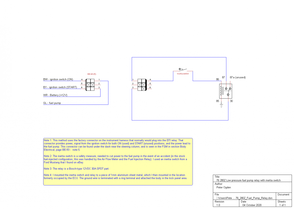
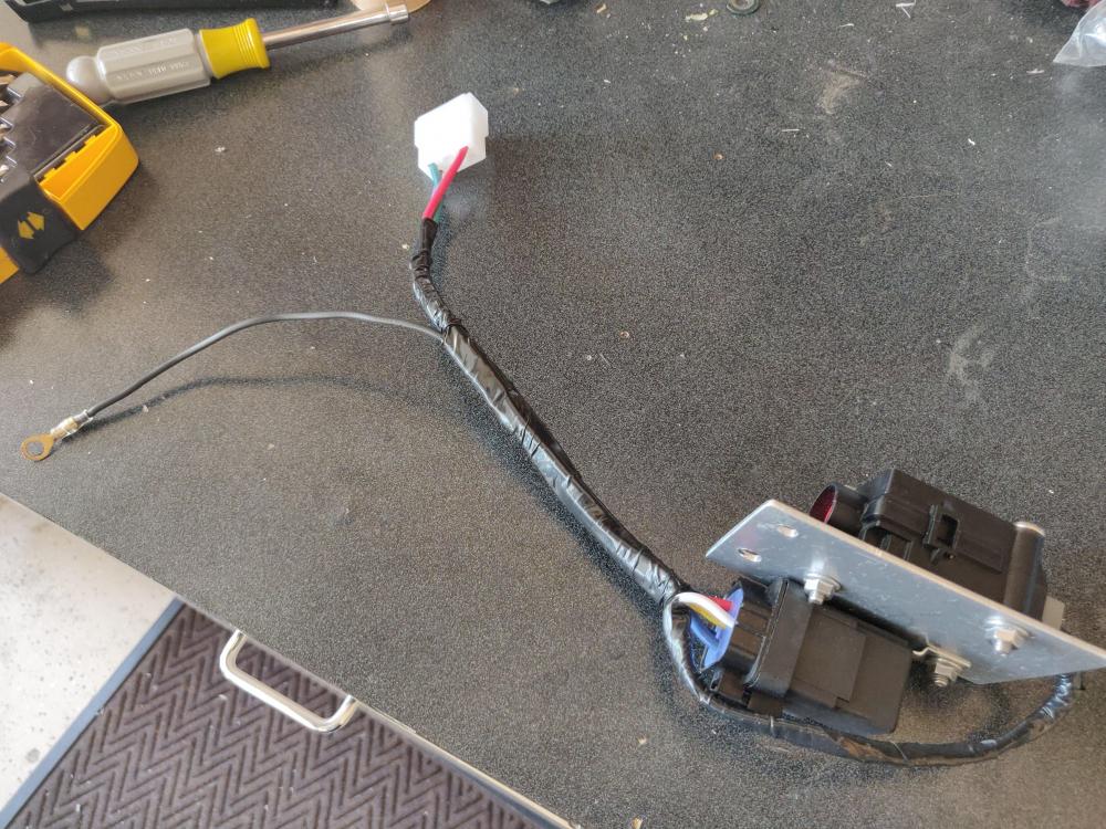
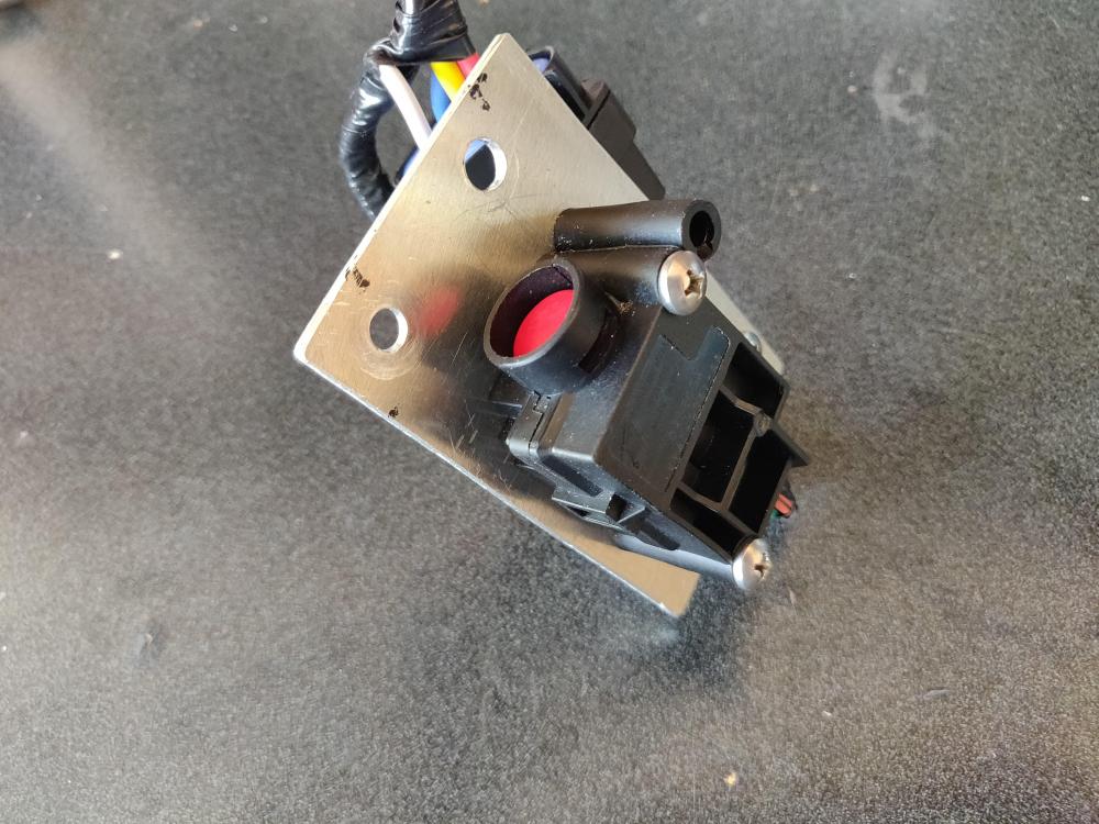
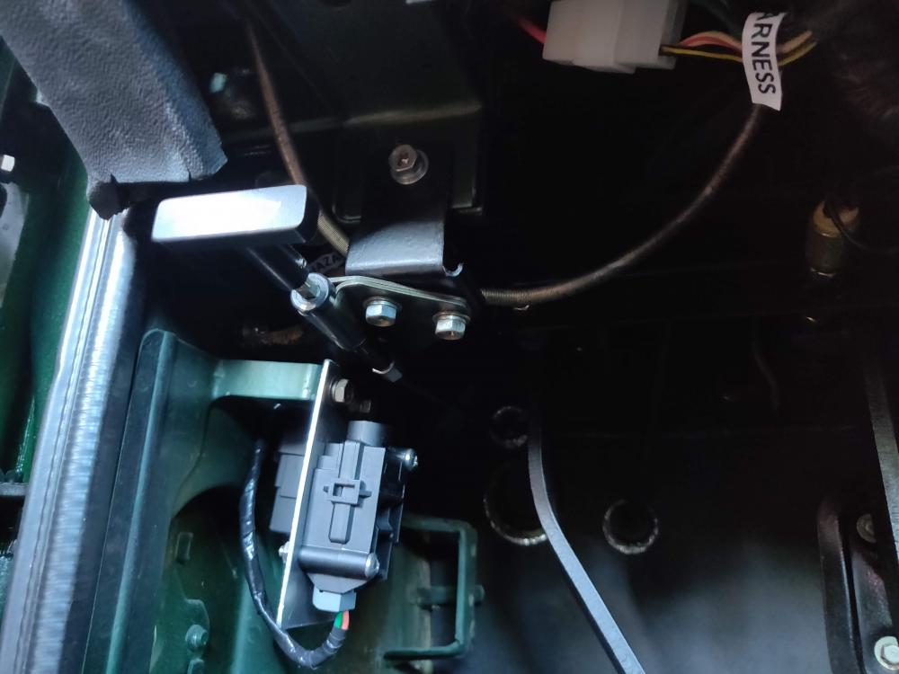
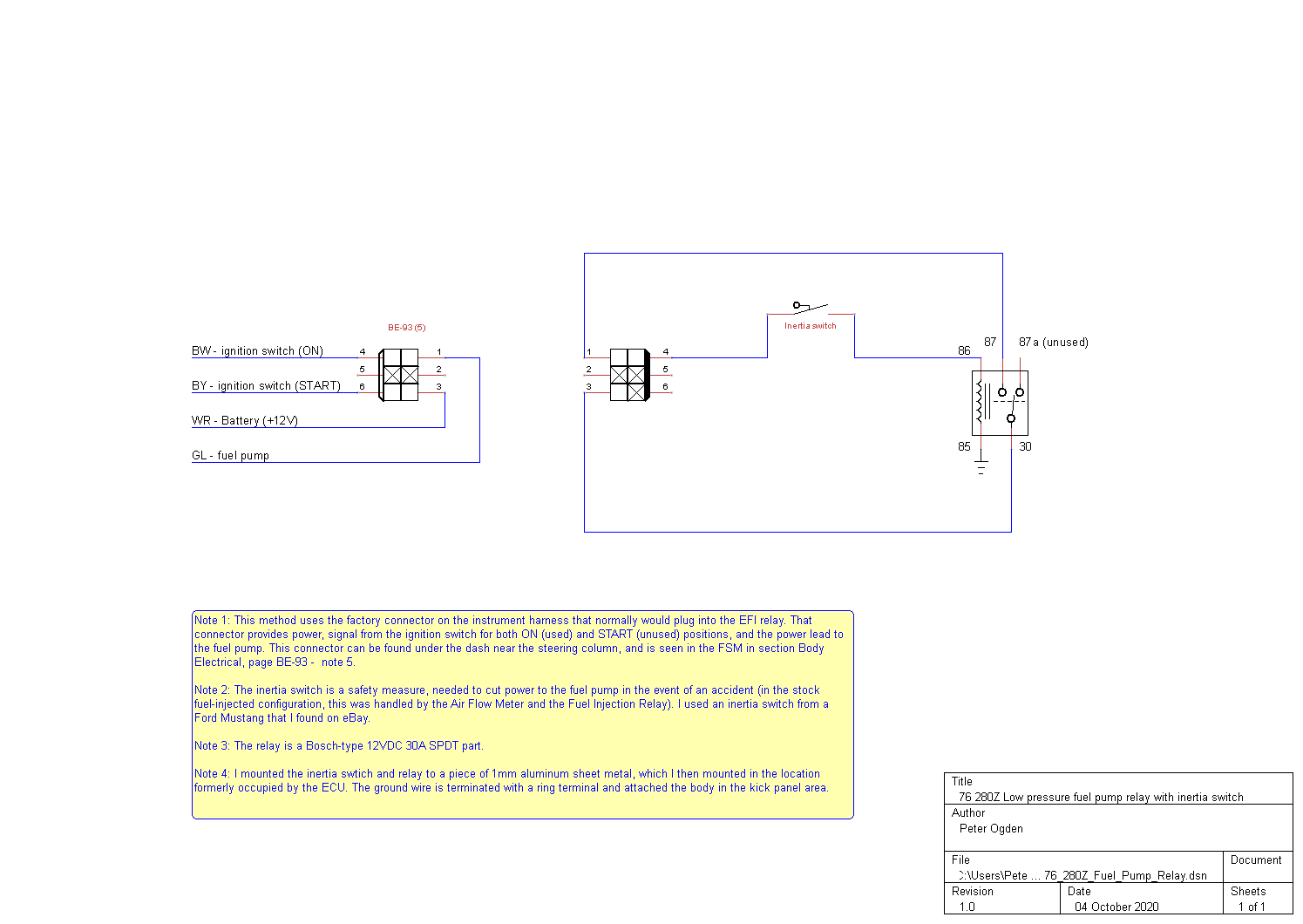
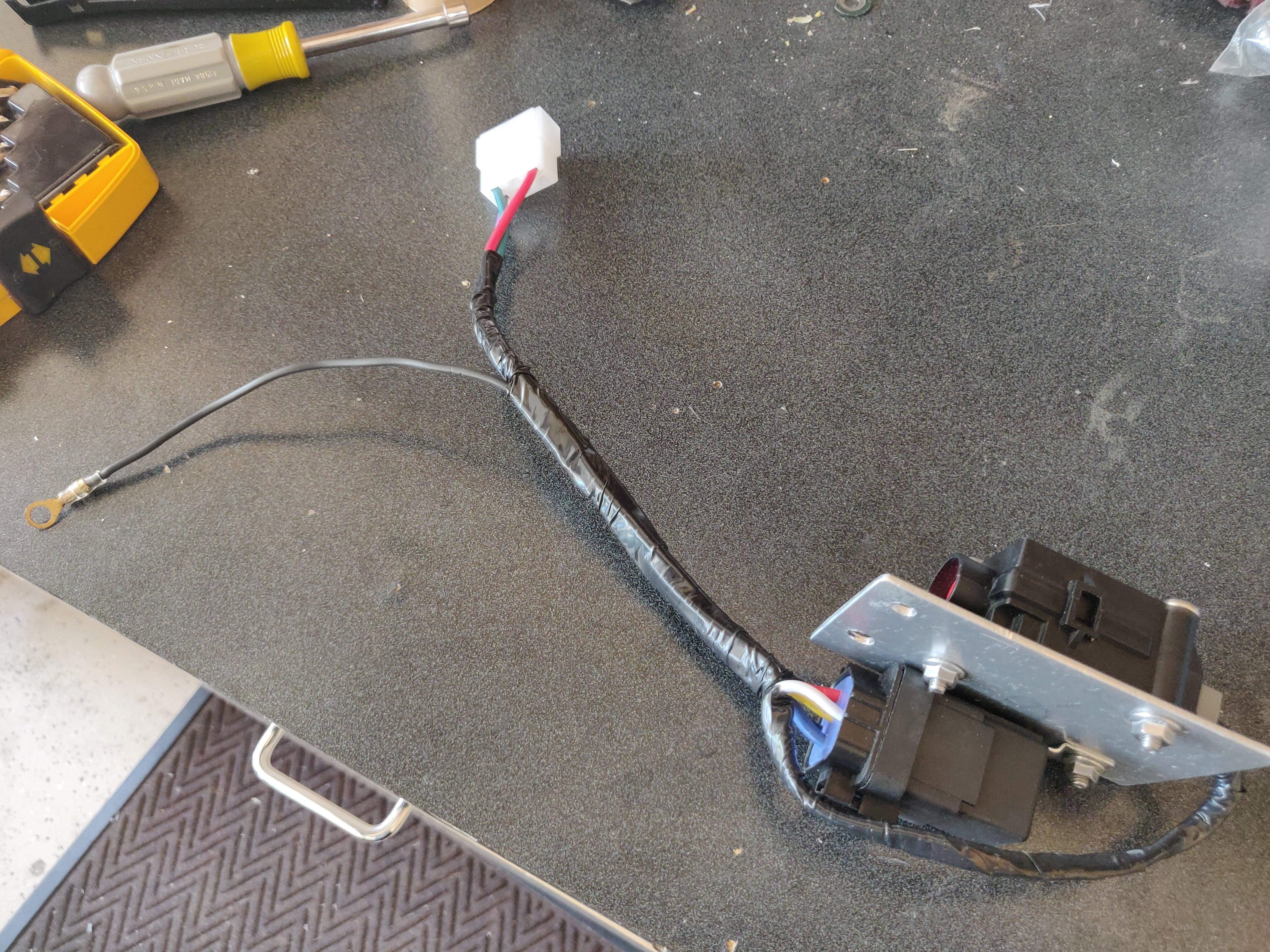
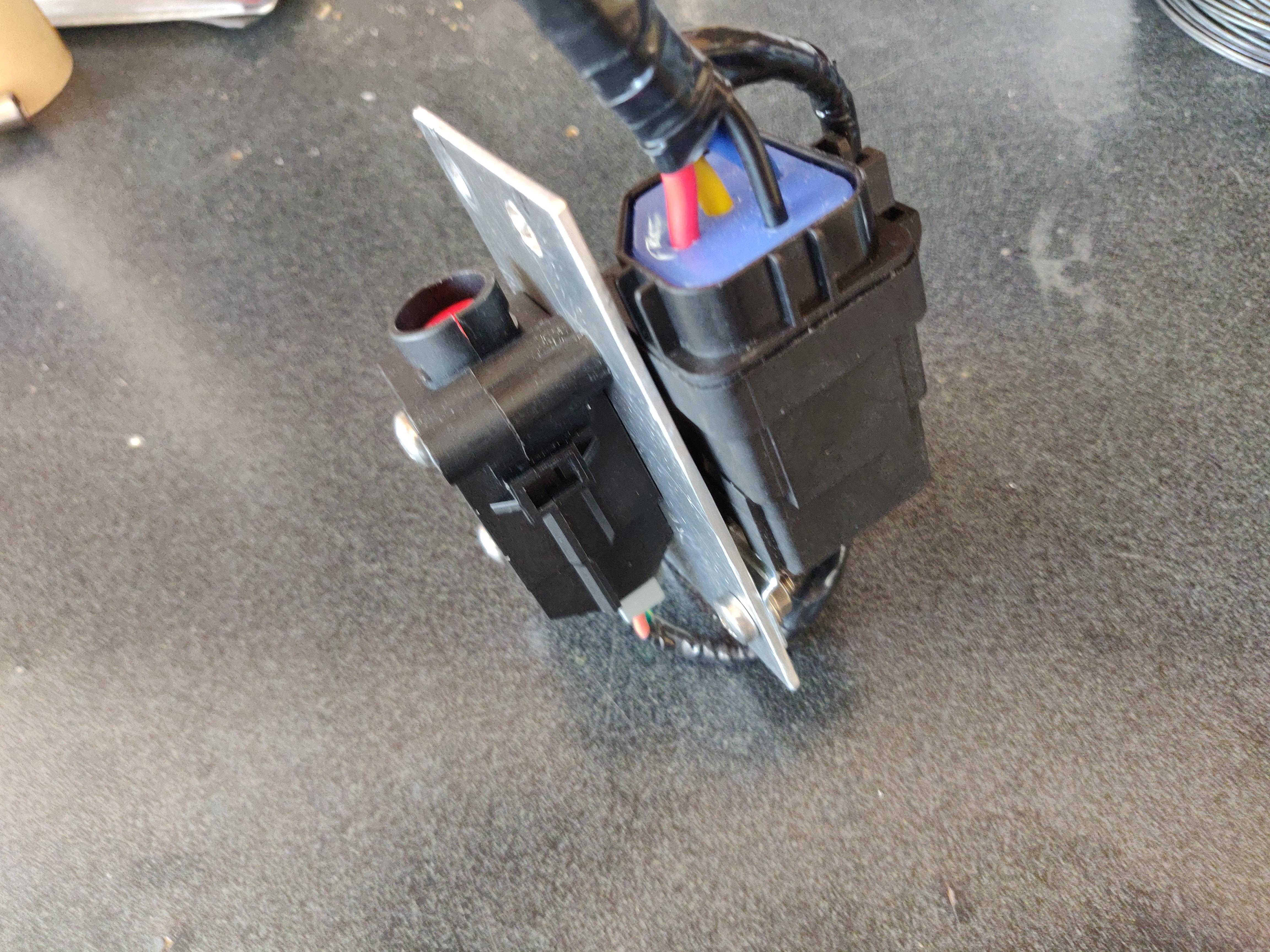
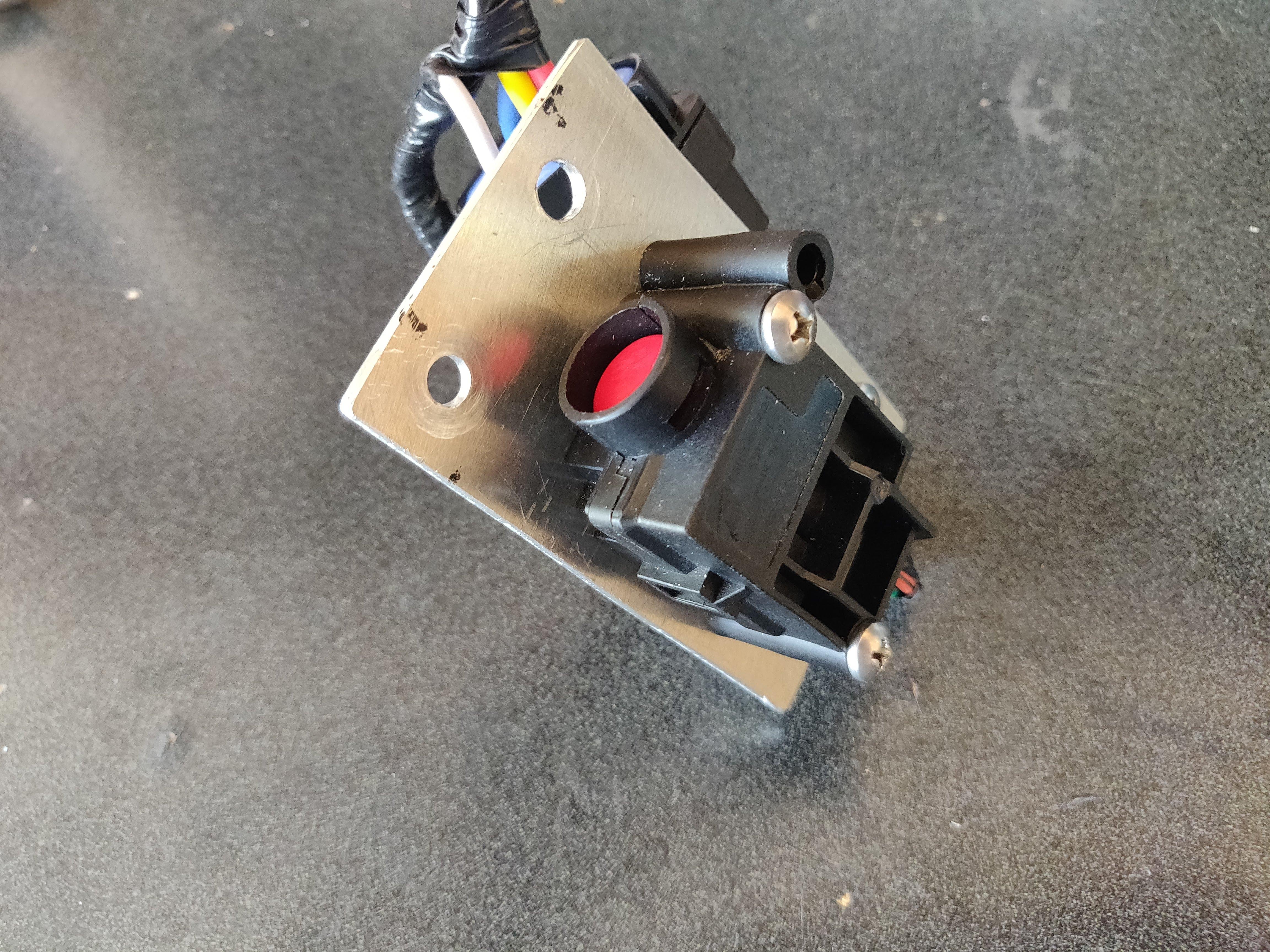
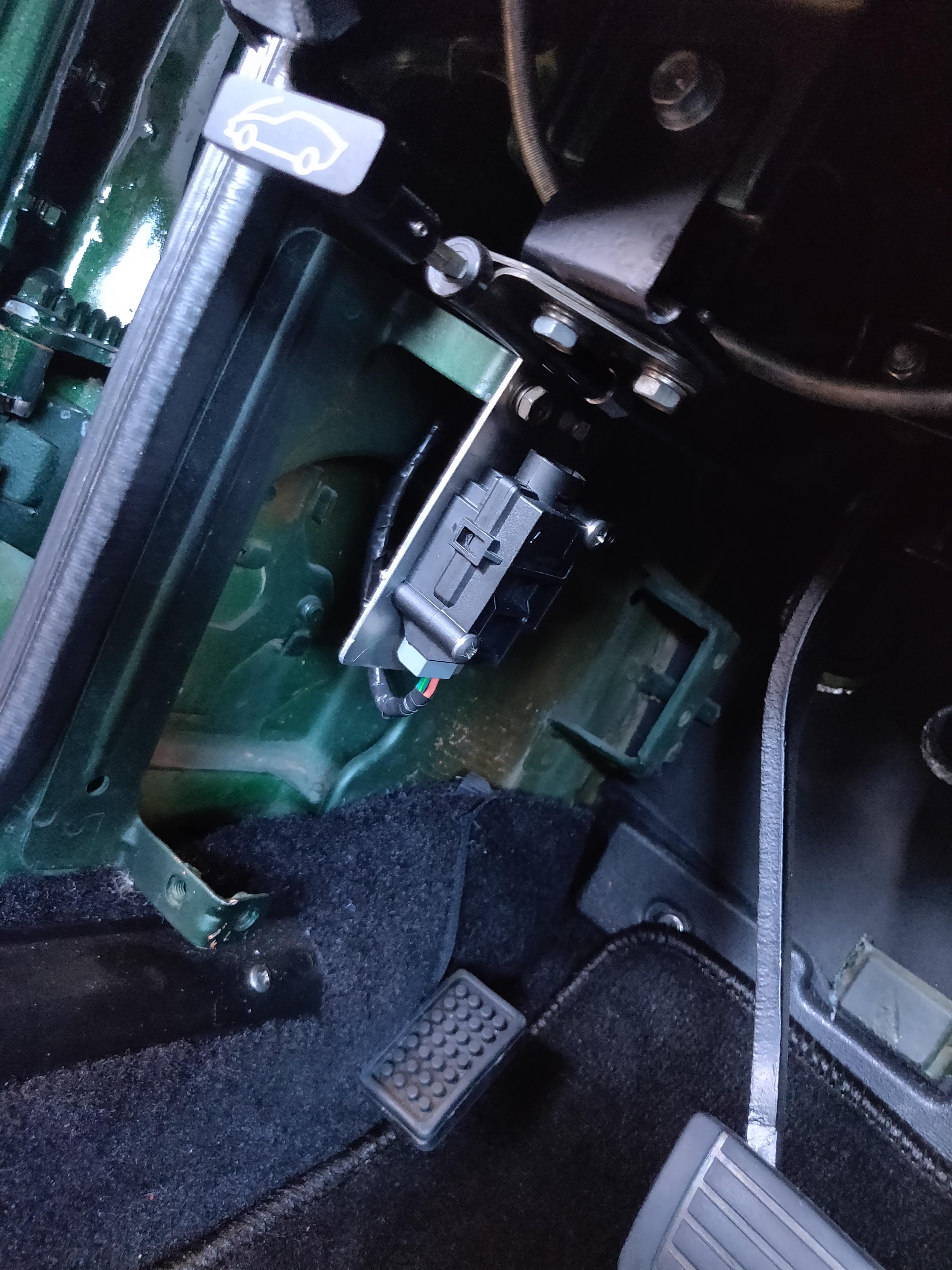
I have a 1976 280Z that was converted to SU carbs by the previous owner. The mechanical fuel pump was crap, so I replaced it with a GMB part which didn't seem to work very well. I replaced that with another GMB pump which seems to work fine. I am aware that some have reported problems with them, so I also installed a NISMO electric pump. In reading on this site about how to wire this up I saw lots of advice about adding an inertia switch for safety. From the FSM and wiring diagram I also learned that the factory fuel pump in my car was controlled by the fuel injection relay, which had been deleted long ago from my car. This article describes one pretty clean way of wiring in a relay and an inertia switch to provide power to a low-pressure electric fuel pump in a carb-converted 280Z. Background: In the 280Z the fuel injection relay is actually two relays packaged together: the EFI bible refers to these as the Power Relay and the Fuel Pump relay. When the ignition switch is in the ON position, the power relay sends sends power to the fuel injection system (ECU, fuel injectors, AFM); the fuel pump relay sends current to ... yep, the fuel pump. The current sent to the AFM doesn't power the AFM; rather, the AFM closes a set of contacts when the engine is running and air is flowing, and it opens those contacts when the engine is off. The current required to operate the fuel pump relay runs through those AFM contacts so that the fuel pump relay closes only when the engine is running and air is flowing. If the engine stops, the AFM contacts are opened and so is the fuel pump relay. It's a little more complicated than this (related to how the Start position of the ignition switch sort of overrides all of this so that the fuel pump can run in order to start the engine), but that's not really important for this discussion - I want the fuel pump to run when the ignition is in the ON or START position, unless I've been in an accident. It turns out, there's an easy way to do this. The connector that (formerly) ran to the Fuel Injection relay is part of the instrument harness and is found under the dash by the steering column. I just replaced the female 6-pin connector (only 4 pins are used) with a similar one from Vintage Connections and then wired the male part to the Ford-type inertia switch and Bosch-type 12VAC 30A relay as shown in the diagram and pictures below. I just mounted the relay and switch to a piece of 2mil aluminum plate, and mounted the whole thing by where the ECU was located. It seems to work: the fuel pump comes on with the key in the ON position, and if I tap (well, smack) the inertia switch to get it to open, the fuel pump turns off. I haven't driven it enough yet to know whether the inertia switch will "break" when I don't want it to (going over bumps, etc.), but it's easily reachable from the drivers seat.


 2 points
 -
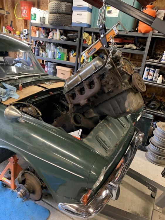
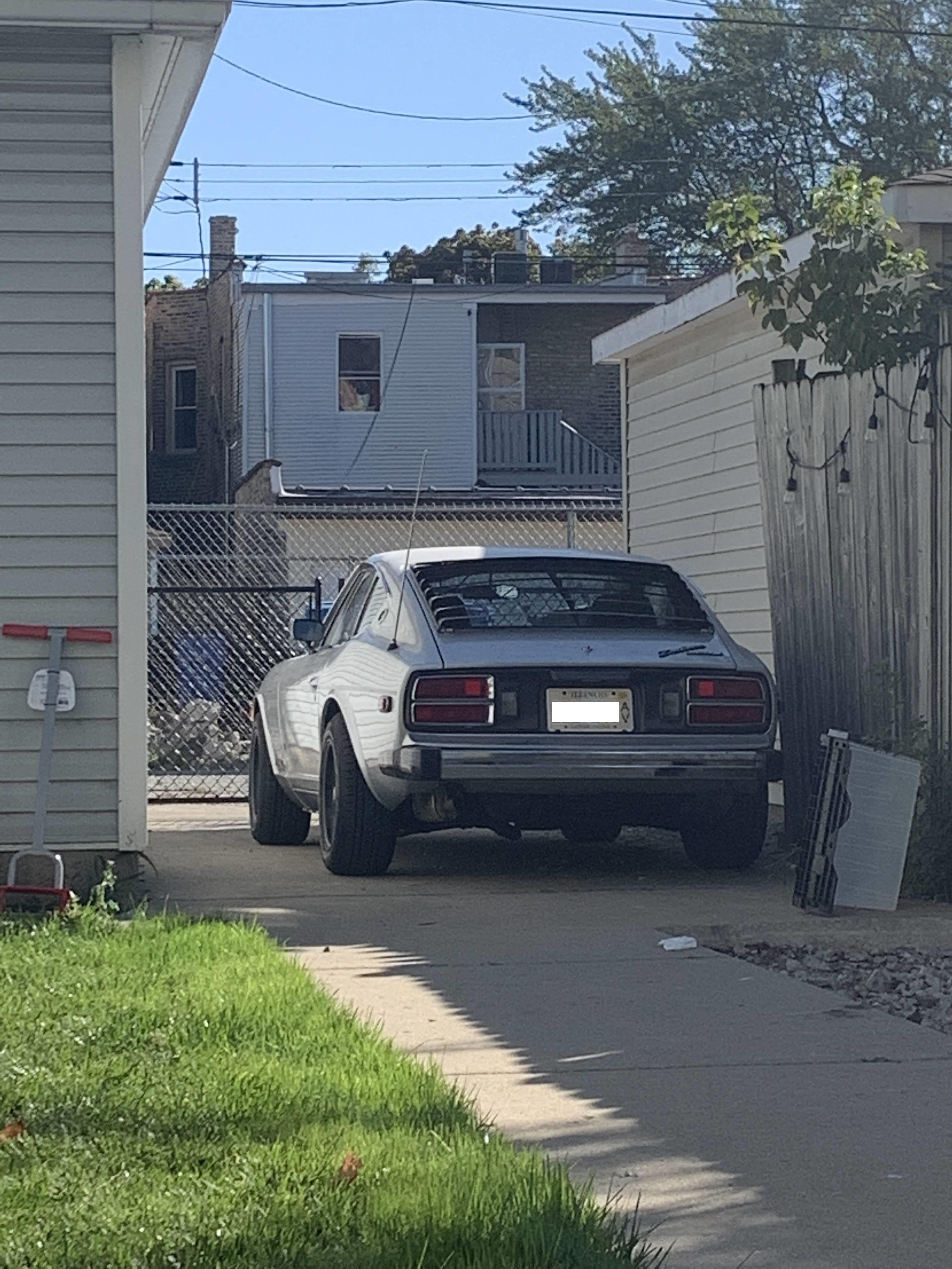
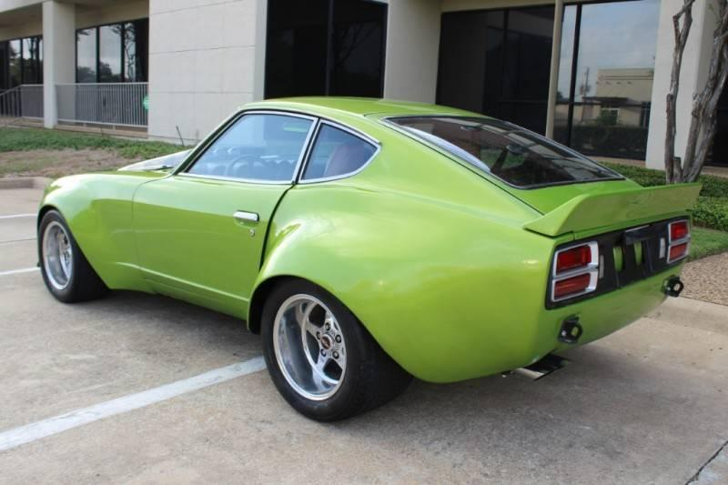
2 points@iscnetwork Planning to give her a bath tonight since she is covered in dust from sitting all year, so more photos to come tonight. In the meantime, something to get your started.
 2 points
 -
2 pointsI bet he doesn’t have problems with exhaust gases in the passenger compartment, eh?2 points
-
2 pointsDon’t even!!!! What you are doing is widening or narrowing the annulus area of the jet by doing that and using different parts of the needle. Do it right and do it once! Otherwise you will waste a lot of time chasing your tail. Ask me how I know. The float adjustment being right is mega important on these carbs.2 points
-
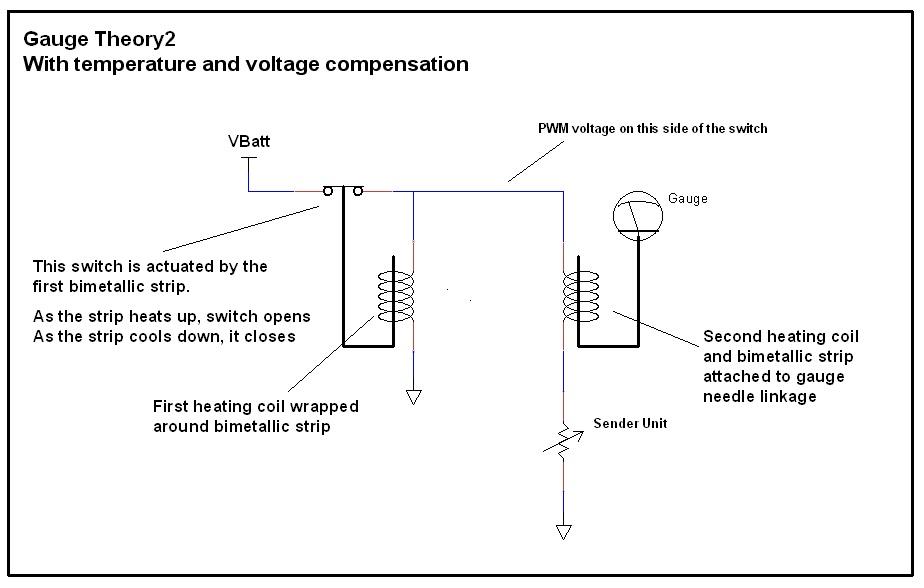
2 pointsLOL. I'm pretty much out of TV shows too. I get it. There are two "stages" to the compensated gauge. One of those stages is he simple gauge we already talked about above. The other stage is the compensating or regulating stage. It's job is to compensate for changes in ambient temperature and varying system voltage. The compensation stage consists of another heating coil wrapped around another bimetallic strip. This bimetallic strip forms an electrical switch such that when the strip heats up, it breaks contact. And when it cools down, it re-establishes contact. The trick is, that it makes and breaks contact to it's own power source and the power source for the simple gauge stage. The result is that this second strip/heating coil combo will make and break the power source such that it will always achieve the same average temperature. Of course the temperature is rising and falling some, making and breaking connection, but the AVERAGE is always the same. Colder day? Power to the compensation strip will have to be on longer to reach the temp that bends the strip to the point where it breaks the switch connection. Hot day? Just the opposite. Power will be on for a shorter time. Low system voltage? Again, power will have to be connected longer in order to heat the strip to the desired temperature,. And conversely, if the voltage is higher, it'll take less time. The result is that the compensation stage creates an ON/OFF/ON/OFF pulse train whose duty cycle and frequency will change depending on the ambient temperature and system voltage. This effectively creates a voltage source that will always supply a constant amount of POWER to the gauge system under all conditions. Clear as mud? Connect that constant power source to the simple gauge from above, and you have this: If you put your key in and turn it to "ON" you should see the gauges start to rise. Don't start the car. Just pick a needle and watch carefully. You'll see the needle start to rise, but probably before it reaches it's final position, it'll pause... Then start rising again. Then pause again. This will continue until it finally reaches it's final position. And even then, if you watch carefully, you'll see the needle actually wiggles a tiny bit. This effect can most easily be seen with a needle that's moving well above minimum like a full tank of gas. That pausing and wiggling is the compensation stage opening and closing.
 2 points
 -
1 pointThanks I like seeing photos of other Z cars. I miss not being in a big city where there is a club of Z owners close by.1 point
-
1 point
-
1 pointCouldn’t agree more! Ztherapy is how all businesses should be run! Bruce and Steve are the best.1 point
-
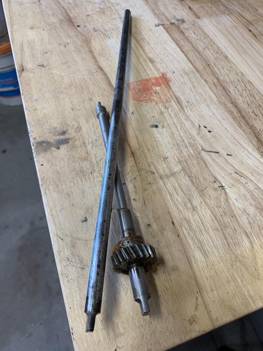
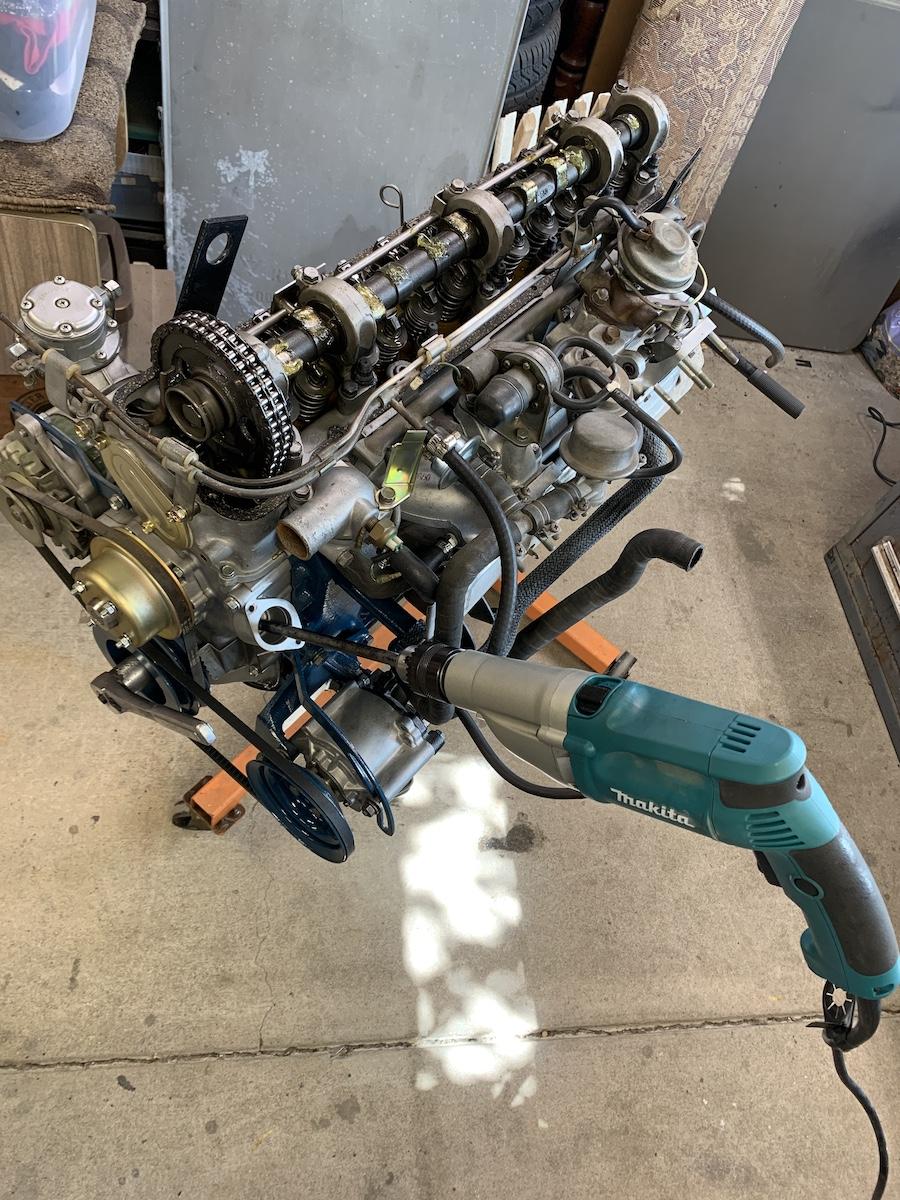
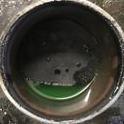
A bit off topic, but primed the motor today. Found a 7/16" diameter rod about 18" long, and ground a flat to fit the oil pump. Ran drill CCW for a minute or two and made sure oil was squirting out of all the cam oiler bar holes. A little messy having to remove oil pump afterwards, but should be good to go.

 1 point
 -
1 pointIssue resolved. Ended up having to retap it. But I now have working brakes. Thank you everyone for your help!!!!1 point
-
1 point
-
1 pointHe bought it in "72 but it has the vertical rear defrost lines? Maybe an earlier car. Weird choice of pictures too, IMHO. Still worth a look for someone in that area.1 point
-
Writing to close this thread, at least from my perspective. I'm rebuilding my '72 Z after decades of waiting to do so. Could not successfully remove my LF strut from its strut housing using the brute pulling force produced by a chain, come -a-long and two trees. Later I tried a daily application of muriatic acid at the top of the strut housing to free the strut. Did this for over a month. The strut did eventually come out but the muriatic acid had destroyed the gland nut threads of the strut housing rendering it useless. The strut had solidly rusted into the strut housing. Found another strut housing on eBay.1 point
-
1 point
-
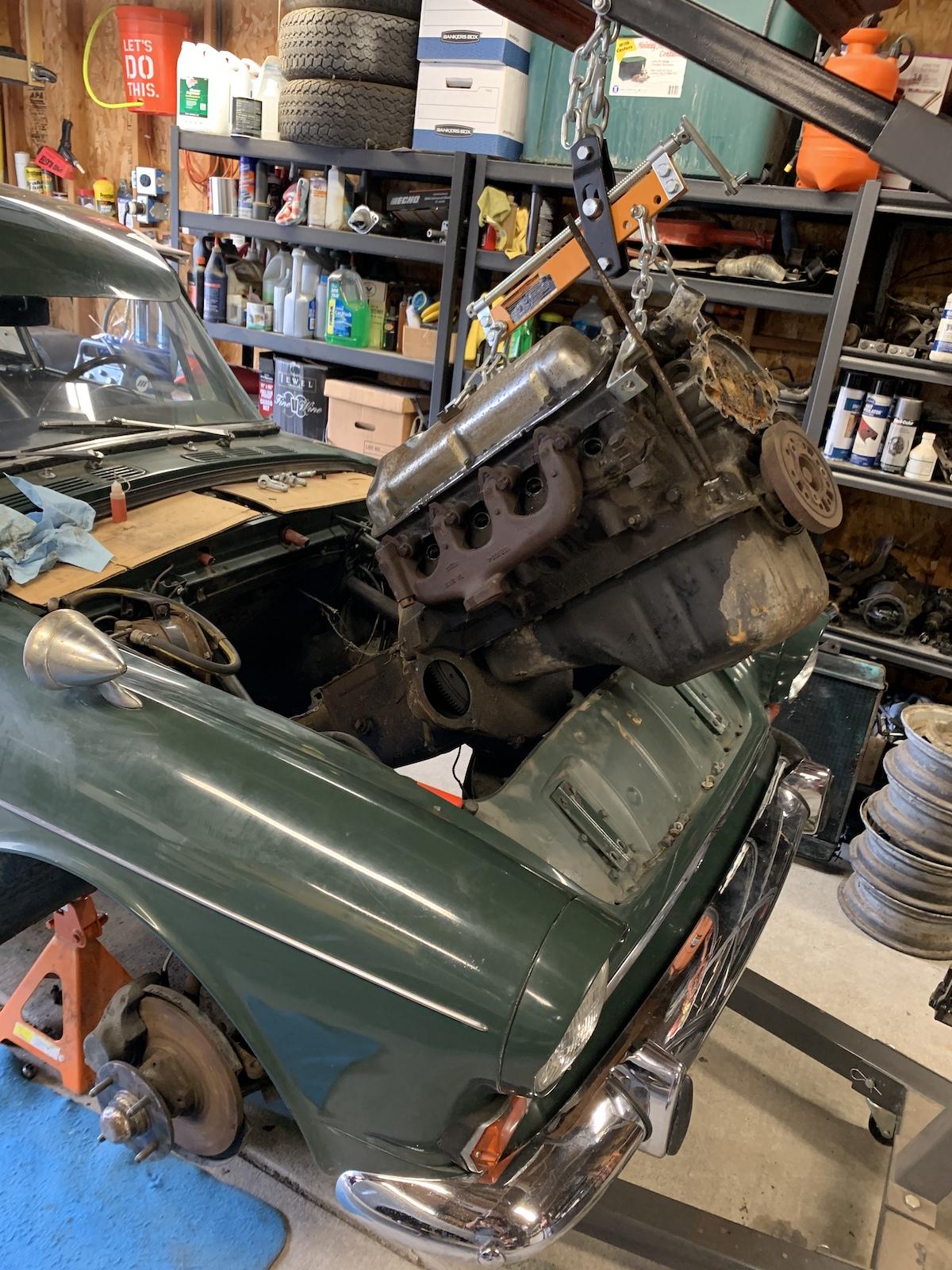
I ended up un-mating and re-mating the transmission about 5 times before the engine went in (see my clutch thread for that fun story). I finally got really good at it. The trick was to get the vertical alignment of the friction disk just perfect. To do that, you have to wiggle it up and down while it’s being held by your alignment tool, and torque down the pressure plate when the disk is in the middle of its range of motion. Once I got that right, the transmission would slide in very smoothly with no issues.1 point
-
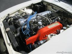
1 point+1 on the return to body color option. You'll have a choice between single stage (like OE) and two stage processes, choose one to best match to current body finish. Going with body color will give the various engine bay bits the best opportunity to be seen.1 point
-
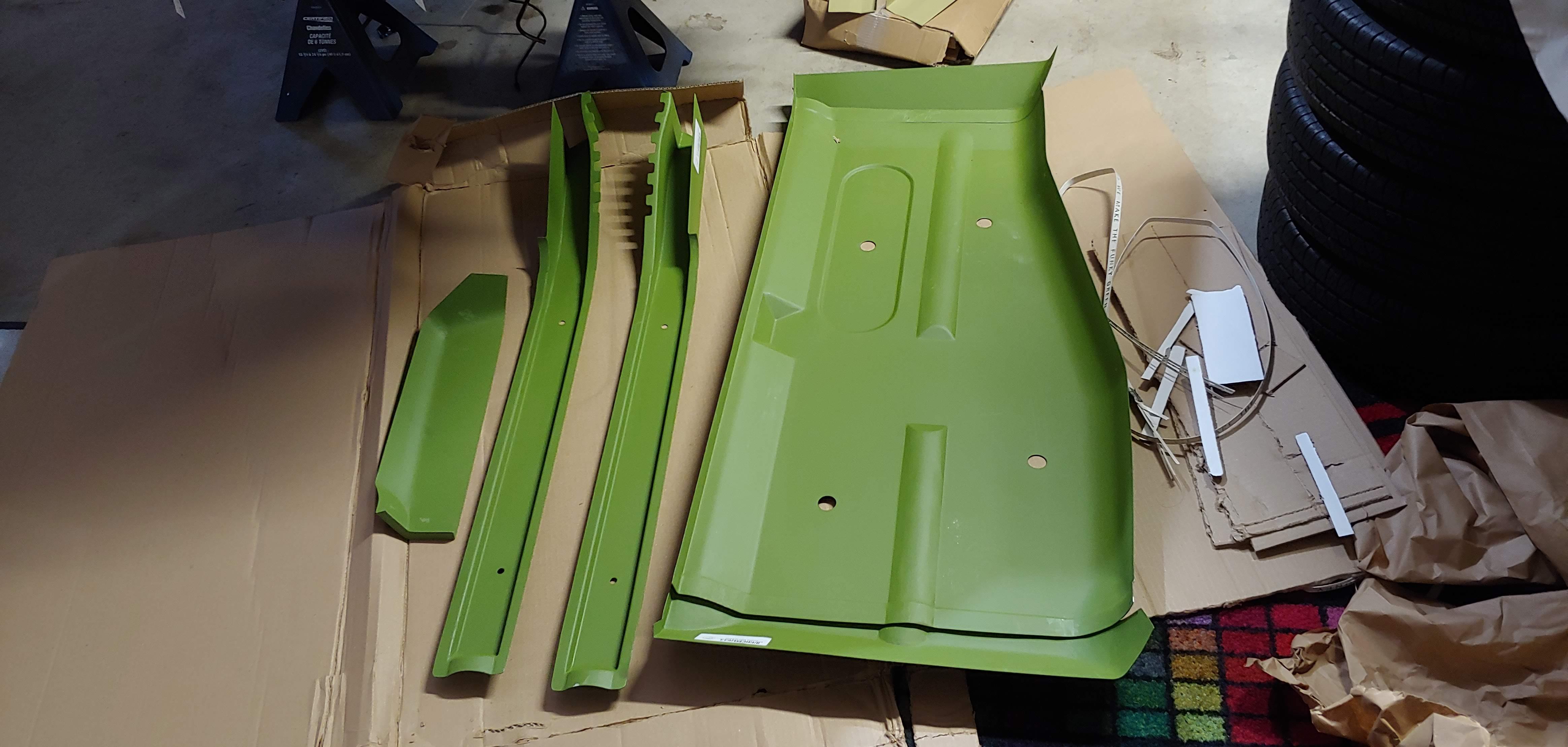
Damn, makes me want to do large scale rust repair again (I'm sure I'll come to my senses shortly). Using pieces like these, assuming they fit, would have made life SO much better on past jobs.1 point
-
I just received my floor pan parts and full rear frame rails from KF Vintage JDM and they look great. I would definitely recommend them. They arrived well packaged in three business days from Bogata Columbia to my address in BC, Canada.
 1 point
 -
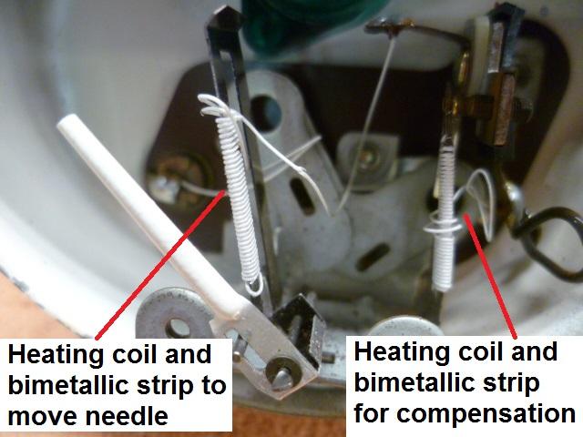
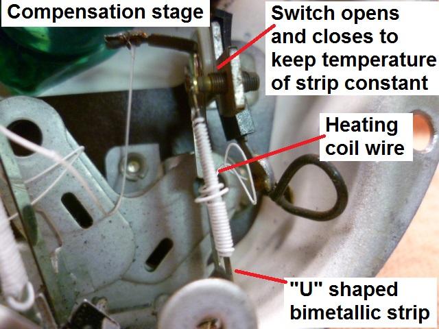
1 pointOK, I will convert this stuff to it's own thread when I get a few more minutes to make it read right. In the meantime.... I have more pics. Here's a pic of one of the gauges. You can see the two different heating coils wrapped around two different "U" shaped bimetallic strips. Interesting to note that internets research indicates that "U" shape is part of the compensation as well. The concept is that the unheated side will compensate some for changes in ambient temperature. "They say" it doesn't get rid of all of the temperature based effects, but it helps some. Between that "U" shape and the compensation stage, the gauges seem to be really stable. So this is an example of the compensated gauge with the two stages: And here's a closer-upper pic of the compensation stage showing it's parts: The switch opens and closes to keep the temperature of the compensation strip at a constant temperature (ave). If you put a Voltmeter on the sender unit, you'll see that it isn't a steady voltage, but is instead a square wave.
 1 point
 -
1 pointI would definitely go back to body color, 918 orange also happens to be my favorite. 😃1 point
-
1 pointi’ll try and double check everything today when i install the new fuel pump as well. i’m hoping the fuel pump fixes my issue . i’ll keep you posted on everything. thank you for the help everyone1 point
-
1 pointHere's the dead giveaway I've seen most often. The metal tang on top of the floats are bent up like a ramp and they shouldn't be. The higher up the less fuel, the needles get pushed in too soon cutting the flow. Here are some pictures I found that will help. This is what you do not want, This is what they look like new so you want them close to this, I say they should look like a speed bump, not a ramp. The needle should be able to move smoothly over the tang up and down like a speed bump.

 1 point
 -
1 pointThis is a lot of reading but you'll be a pro when you read it all. https://www.google.com/search?q=240z+float+levels+classiczcars.com&rlz=1C1BOFA_enUS494US494&oq=240z+float+levels+classiczcars.com&aqs=chrome..69i57.12013j1j7&sourceid=chrome&ie=UTF-81 point
-
1 point
-
1 point1 point1 pointI had the same problem, on the garage floor. I thought I had a wrong 5 speed. It was tough.1 pointYeah, that seems to work okay with trans studs into bell housing, but not so much for bell housing to block. Install has gotta be a be a bit easier than my Sunbeam Tiger! Engine has to be pulled with trans to get to trans or clutch. Tight fit! 😓. On Tiger you can go out the top, or drop subframe and drop out the bottom. Choose the scary way.
 1 pointLet me chime in on the transmission FILL and DRAIN plugs... (begin rant) I have no clue why people tighten these SO TIGHTLY! It's un-necessary. In my former life I was a licensed Journeyman Plumber (Ret.). Actually, I guess I still am a licensed Journeyman Plumber - just not employed as such... What in the crap does this have to do with transmissions you ask?? THOSE PLUGS ARE PIPE FITTINGS (well, they have pipe threads...) So, now that you know that I am eminently qualified to speak on the subject: - Go the Home Depot. Plumbing Department. BUY an entire roll of TEFLON TAPE. - Go home. Properly apply (ya, just wrap that sucker up with tape) the teflon tape following the manufacturers directions to the male threads of BOTH PLUGS - BEFORE you install them. - Tighten the plugs (BOTH PLUGS) ONLY ENOUGH so that they don't leak! There is NO pressure inside the transmission (like there is in your Natural Gas line or your galvanized water pipe) SO THE PLUG DOESN'T NEED 80 FT/LBS OF TORQUE. Seriously, you can practically screw them in by hand if you use teflon tape or good pipe dope (just kidding (exaggerating really) you need to snug them up.) But you really, really can stop over tightening those plugs. How do I know? Come and remove these plugs from MY transmission. Be a plumber - even if you don't want to - for me... (end rant);1 point1 pointOK, I promised to describe how the gauges work... Not sure it should be here in this thread, or if I should start a new thread for this. I'll put this here for now, but if people think it should be separate let me know and I'll start a new specific thread about gauge theory. So in order to understand how the gauge system works, I think it would be a little easier to first understand how they DON'T work. I think everyone already has a good handle on this simple system, but it's an important place to start. Here's a pic of a simple (uncompensated) gauge design. Wrap a heating coil around a bimetallic strip and mechanically attach that strip to the linkage of a gauge needle. Flow current through that heating coil and to a sender unit who's resistance reflects the level of whatever you're trying to measure (temp, oil, fuel, whatever). As the resistance of the sender unit changes, the current through the heating coil changes and that changes how hot the bi-metallic strip gets. The lower the sender resistance, the higher the current. The higher the current, the hotter the bimetallic strip gets The hotter the strip, the more the needle moves. Here's a pic: This simple uncompensated gauge system does "work", but it is subject to a few real-world outside influences that can affect the accuracy: First, since the whole thing works on the temperature of the bimetallic strip, the gauge will read differently on a hot day than on a cold day. And second, since the gauges are powered by the battery system of the car, changes in that system voltage will affect the gauge readings. The gauges would read differently sitting with the engine off than they would with the engine spinning at 3000 RPM when the alternator has kicked up the voltage a bunch. The system voltage can vary from about 12V to over 14V and the gauge readings would change as the voltage varied. So the basic gauge system above sorta works, but these two real-wold effects are undesirable. If the above basic gauge system makes sense, I'll get into how they compensate for those two real-world effects.
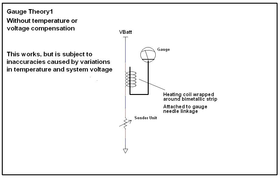 1 point1 point1 pointI’ve used that 13/64 bit quite a few times with good results. As you mentioned centering the bit is key.1 point1 pointHi Guys - looks like "The Z Car Home Page" at ZHome.com is back on-line now.. thanks, Carl1 point1 pointThanks for the heads-up - - Small issue with the LAN - should be back on-line by end of day.1 point1 pointI tried "Animal Farm" and still got Cuup... “All animals are equal, but some animals are more equal than others.”― George Orwell, Animal Farm “Weak or strong, clever or simple, we are all brothers.”― George Orwell, Animal Farm https://www.goodreads.com/quotes/tag/animal-farm1 point1 pointSo it's an f 150 forum, girls drive trucks they also wear bras. The 2 UUs look like boobs although very saggy ones. Zed Head is a web master. He's going to get some funky ads. Chrome is not that tough, he needs google Tungsten.1 pointThat front bumper looks like a good place to sit when parked at scenic overlooks. Dennis1 pointhttps://seattle.craigslist.org/see/cto/d/seattle-1978-datsun-series-v8/6939207855.html This one's been on sale for awhile. Maybe the owners weren't too sure about the quality of the late c3 Corvettes. Personally, I love the late '70's - early '80's Corvettes/Trans Am's/Firebirds..and if a GM small block belongs in anything, it's one of those. Just my opinion though.
 1 point1 point1 point1 point1 point1 pointI hate to burst your bubble but the back straight at Road Atlanta isn't flat enough to land an aircraft full of marijuana. Nice video from a guy who wasn't 'there'. However...I was there and the stories are relatively true. When we took our GTU Porsche to Daytona in 1980, I got to be chums with the mechanics on this car. One of a pair imported from Columbia. They came in heavy and went home light.
 1 point1 point


Important Information
By using this site, you agree to our Privacy Policy and Guidelines. We have placed cookies on your device to help make this website better. You can adjust your cookie settings, otherwise we'll assume you're okay to continue.