Leaderboard
-


siteunseen
Free Member5Points14,904Posts -

bpilati
Administrator4Points1,750Posts -

ETI4K
Free Member3Points382Posts -

Mark Maras
Free Member3Points3,708Posts
Popular Content
Showing content with the highest reputation on 06/16/2021 in all areas
-
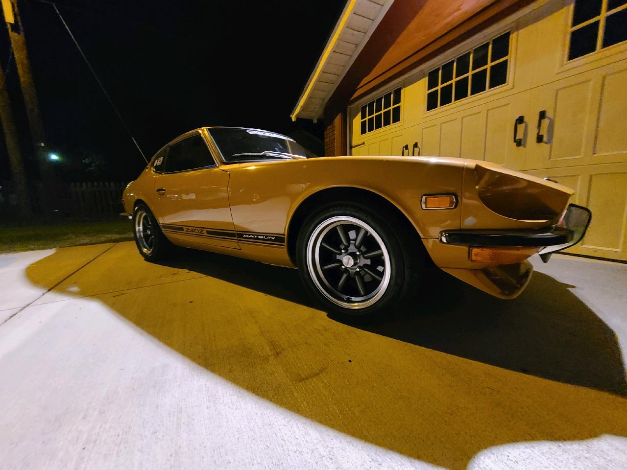
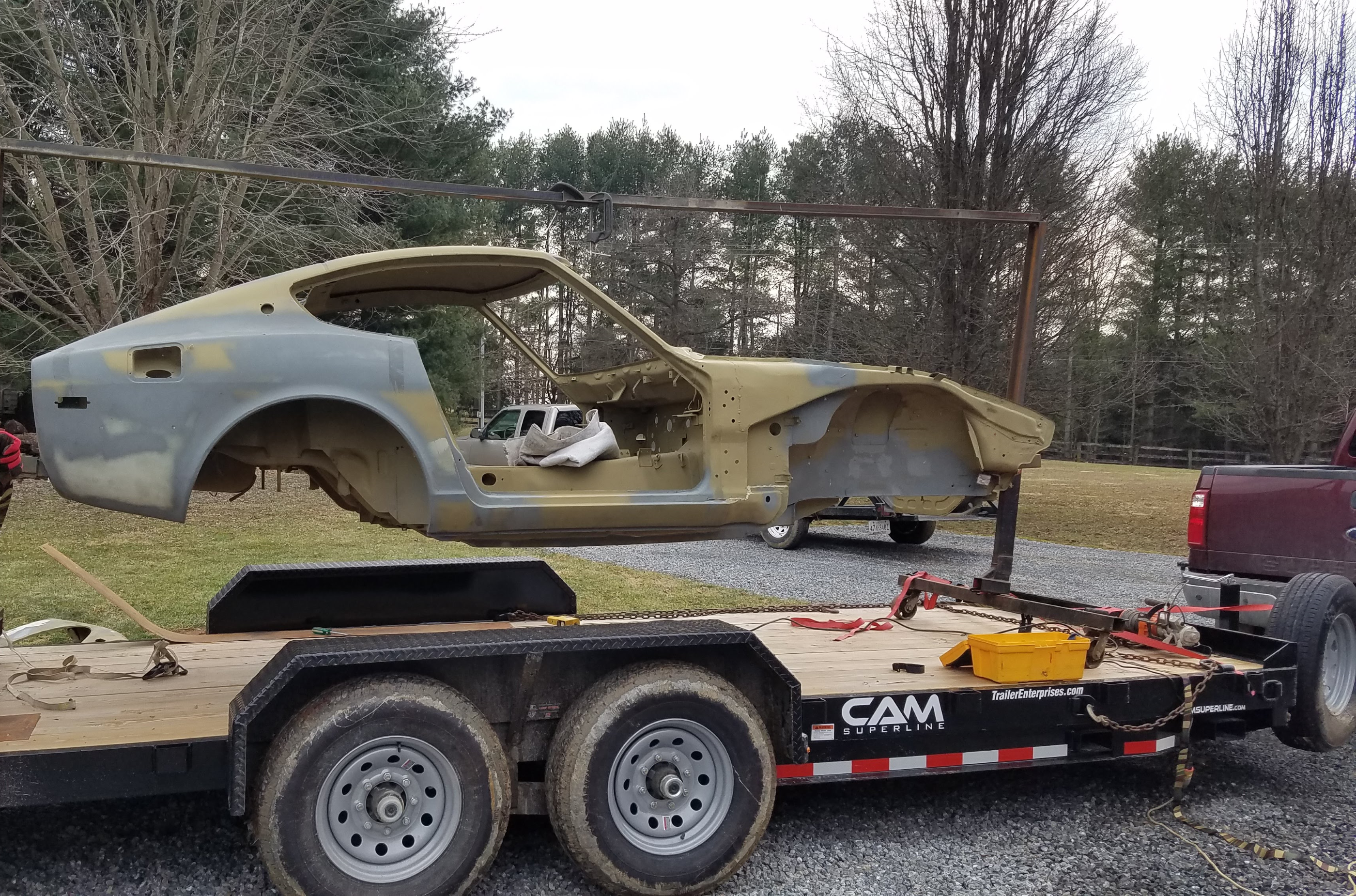
A "quick" paint will diminish the value of your car. Don't be a cheapskate. BTW 240Zs didn't have clear coat. They were painted with single stage paint.2 points
-
 2 pointsHere's a little math for you to ponder: According to the Sunoco article that is referenced by CO in an earlier post, their then-current 'Supreme' fuel blend had a density of 5.95 lb/gal, while their then-current 'Regular' blend was heavier at 6.06 lb/gal. So the Supreme weighed about 1.8% less than the Regular. To make things easy, let's say that the Hitachi-SU float has a cylindrical cross-section and is constrained to move vertically. In this way, a change in fuel density results in a change in float height that is directly proportional. Let's now say that we're starting with the light Supreme fuel in the float bowl. The top of the cylindrical float rises to a height of 'Y' mm above the floor of the float bowl. Let's make Y = 50mm. Then we drain the float bowl and replace it with the heavy Regular fuel. The float doesn't need to sink as low in this heavier fuel in order to displace its weight, so the top of our cylindrical float now sits higher (relative to the floor of the float bowl) by 1.8% and 50mm becomes 50.9mm. That is, the float has risen by 0.9mm. That kind of math doesn't fully explain the crazy float angles we see with the Hitachi-SU's in practice. I think what's going on is a combination of a few geometrical factors: The immersed part of the float is sightly conical, rather than cylindrical. The Hitachi-SU float doesn't actually move in a pure vertical direction. Instead, it's vertical path follows an arc (which may explain why the bottom part of the float was made slightly conical) Once the float passes some particular 'tip-up' angle (relative to horizontal), I suspect that the change in the cross-sectional shape of the immersed part as a function of immersion depth begins to get really non-linear. To add to the non-linearity of the float behavior (hydrostatics?), the contact surface of the metal shut-off tab also travels through an arc (which may explain why its contact surface is curved, rather than flat). It's not clear whether that curve accurately compensates for the arc in the travel path. There may be, once again, a point-of-no-return, beyond which the tab-to-shutoff pin contact behavior goes non-linear. This would be an interesting simulation exercise for someone with the time and the curiosity to pursue it. It's mostly 2D geometry (the conicity of the float makes it somewhat 3D), but it's hard to do on paper. Easier with a CAD-CAE program (which I don't have).2 points
 -
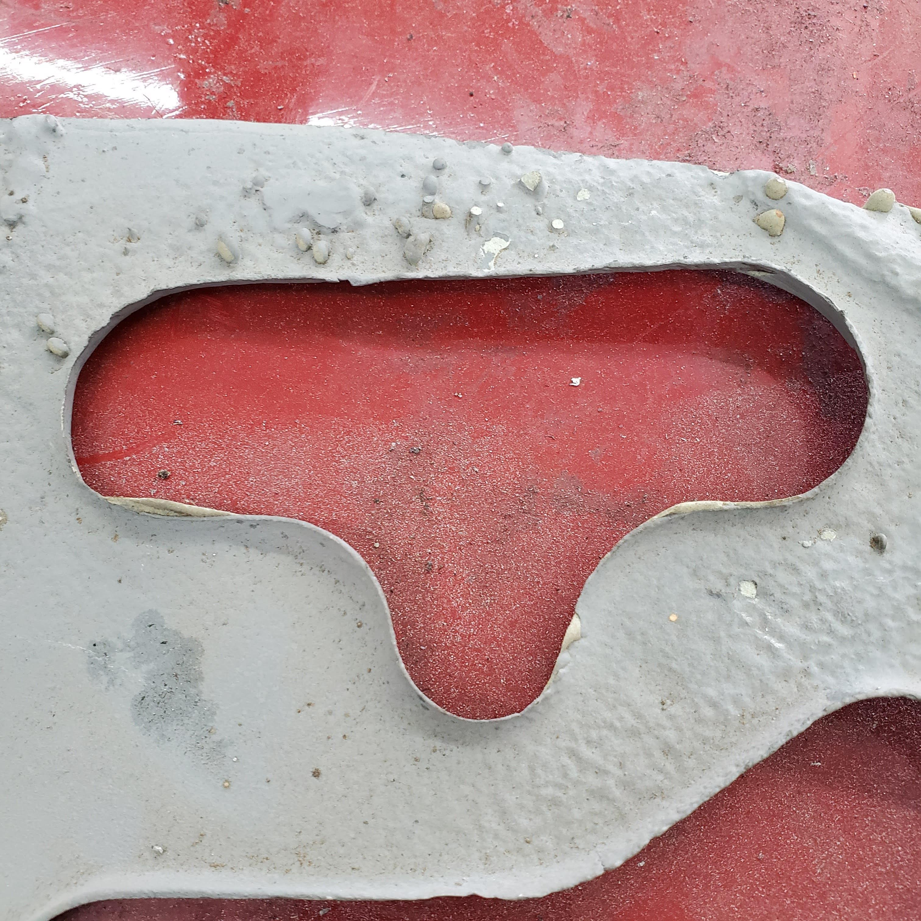
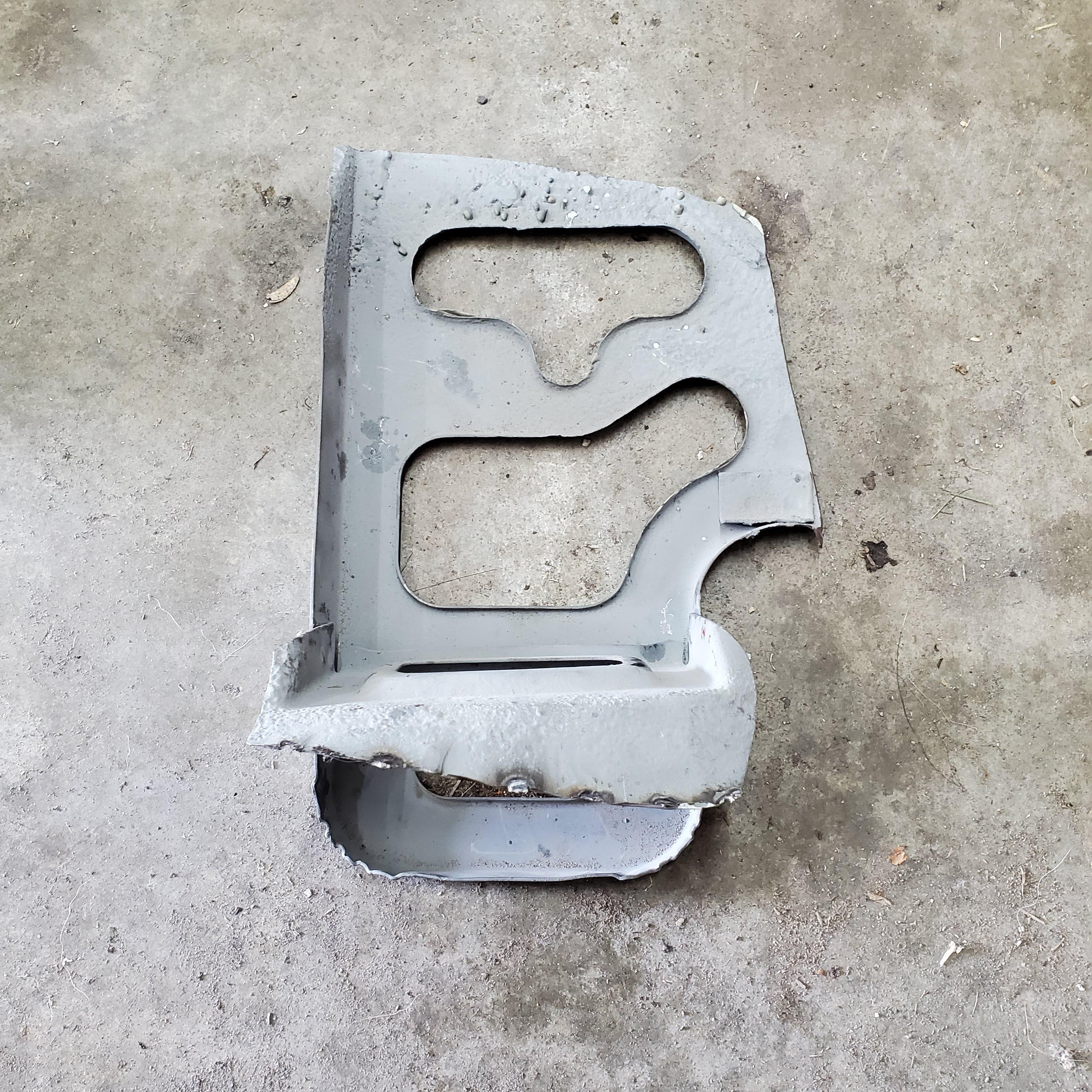
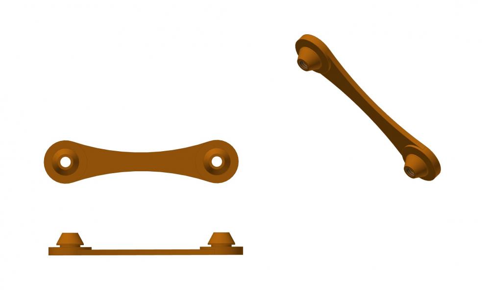
2 pointsNext up to deal with is the battery support. When I started this resto in '97 or so, I removed the battery support to repair that corner's sheet metal. Had to replace several areas completely. I'm not really sure what my thinking was at the time, but when I put the battery support back in I did an amazingly bad job and have never been happy with it. So I cut it out again to correct it without any real idea as to how I would go about it. This is the only before picture. What's significant is the tack welds I used at the lower support - specifically, I burned off(?) any protective coating when I welded it back in, thereby guaranteeing a future of new rust. The angle between the inner fender and the battery support bracket is so acute, it will hold anything and everything and never let it out. So, sand, dirt, leaves, insects, etc. are all guaranteed a place to stay forever - or least until the sheet metal rusts away again. Upon removing the support, what I saw made me glad I did it. When the car was sandblasted it revealed some good perforation damage. Having had no other way to deal with the problem, I had applied mud to the rust holes in the support. This car has not been wet since 1997 and you can see new rust already forming around the rust holes. After seeing what MSA wants for a new support (the better part of $500!), I decided to make a new one. After taking that decision, I struggled with how to reattach it. It seems the idea of welding in the area is asking for trouble. So I decided to make it removable. Two bolts in each of three flanges to permit easy access for cleaning (though infrequently) and any remediation of rust that may occur. To further improve complicate it, I will use snap-in plastic nuts for the bolts to provide isolation from paint-to-paint contact, allow some air space between the parts, and eliminate the need for wrenching on each side of the fender. If I could cut square holes, I'd just order them from McMaster as individual nuts, but I ain't spending a couple of hundred dollars for a square chassis punch. That means I get to print them. Image below is concept. I will make them a bit more rugged. It's surely be no fun to be driving along with a battery dragging under the car attached by two cables. 😁 I should have the new support finished up tomorrow. More to come.


 2 points
 -
2 points
-
How come your score is bigger than mine? I'm suffering from score envy. 😅1 point
-
I had mine buffed down to slick original color. Single stage allows that. Good luck with it. Nice looking car.1 point
-
So if you do quality work on the restored portions (assuming the rest of your paint, and rubber components are very good), you can detail and buff the rest. A good painter can try to match color. All this and you might get by with it.1 point
-
If it had clear coat it's not original singal stage paint the original to the early Zs. My 9/76 has singal stage paint. It fades but that's it, no clear coat failure. My cars, my guess is if you have clear coat spots it's not the original paint. Paint it to your taste.1 point
-
Agreed. There aren't many things worse than a cheap paint job. They tend to raise uncomfortable questions, the most damaging being, 'What's he trying to hide?'.1 point
-
 Just went out and measured my 73. The way you have it sitting it needs to be 7 7/8" off the frame rail, close as I could get. The distance from the firewall is 7/8" measured at the front on the flat part, and also 7/8" measured on the square bump out, it appears the tray is at a slight angle for that to happen. Maybe CanTechZ can/should verify my measurements. Hope this helps. Bonzi Lon1 point
 -
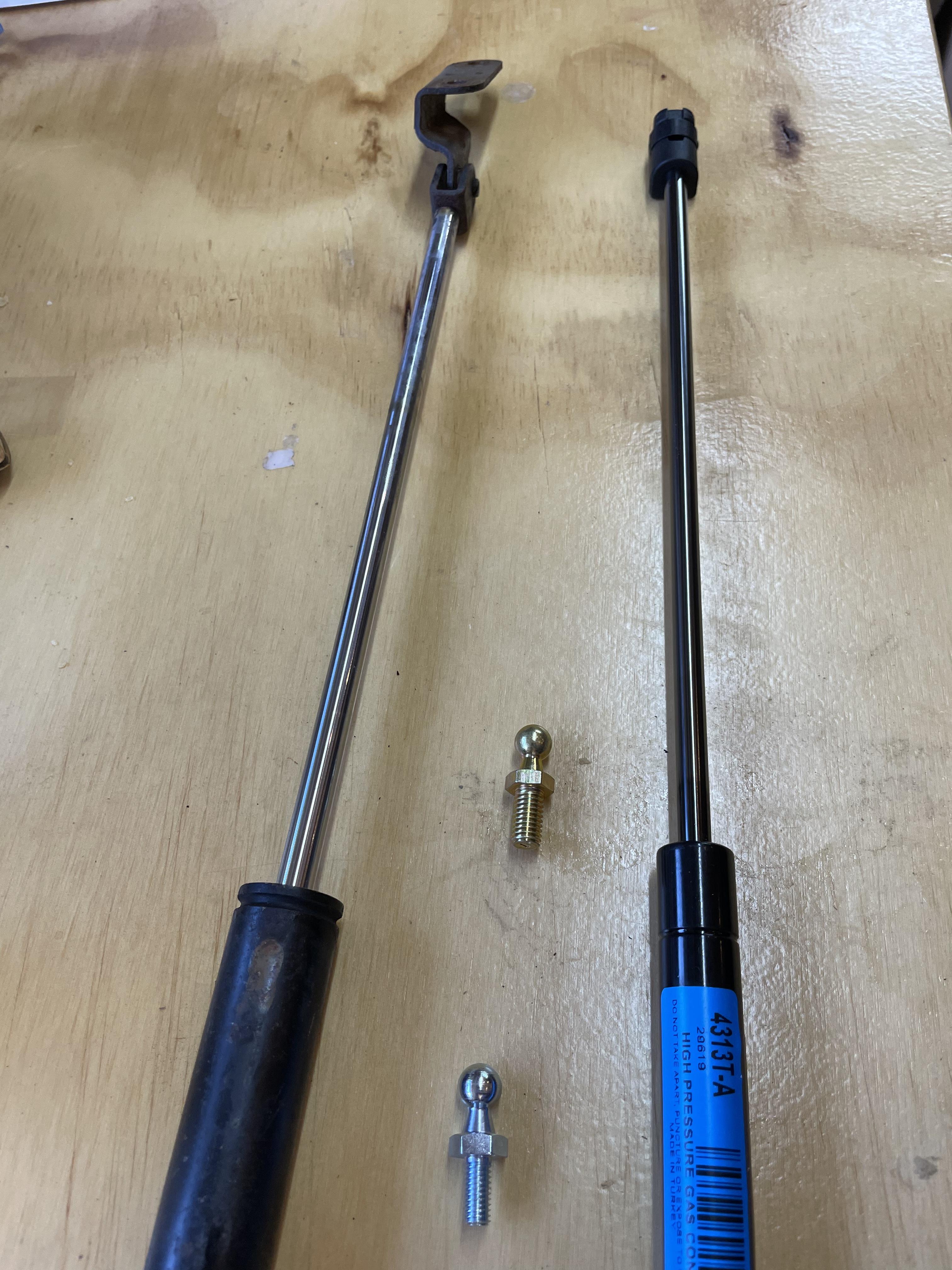
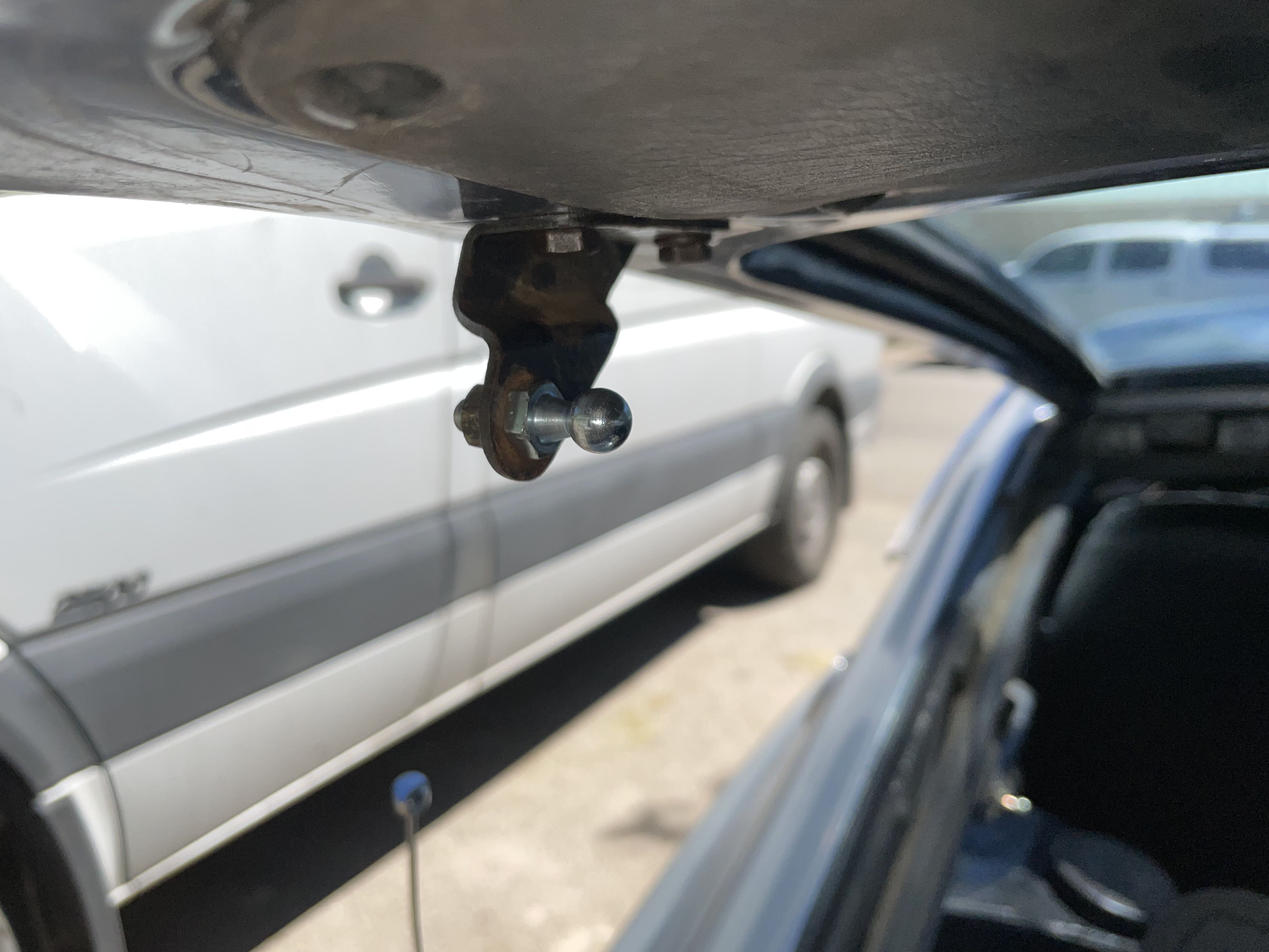
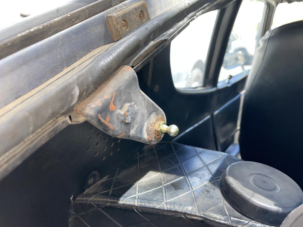
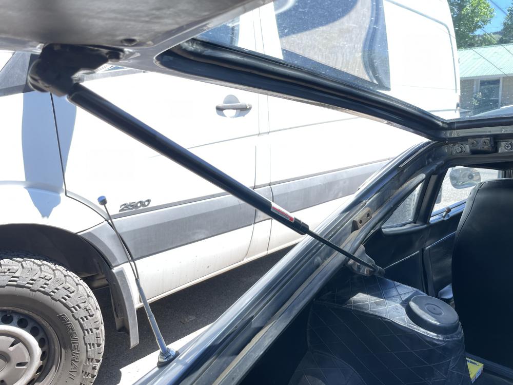
 1 pointJust installed mine from Lift Supports Depot on a ‘71 240z! All hardware included and took 20 min. I did have to source a 8mm nut and washer for the body ball mount thought.
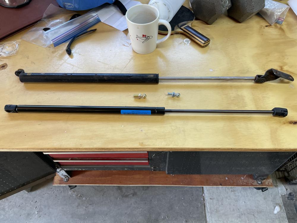


 1 point
 -
 1 pointSince the thread quality isn't an indicator of the quality of the potential failure point your worry level should be the same. Your "new" used axle is just as likely to fail as your old used axle.1 point
 -
 If no one posts sooner, I will get this measurement for you when I get home from today. My Car is disassembled so it will be easy to get.1 point
 -
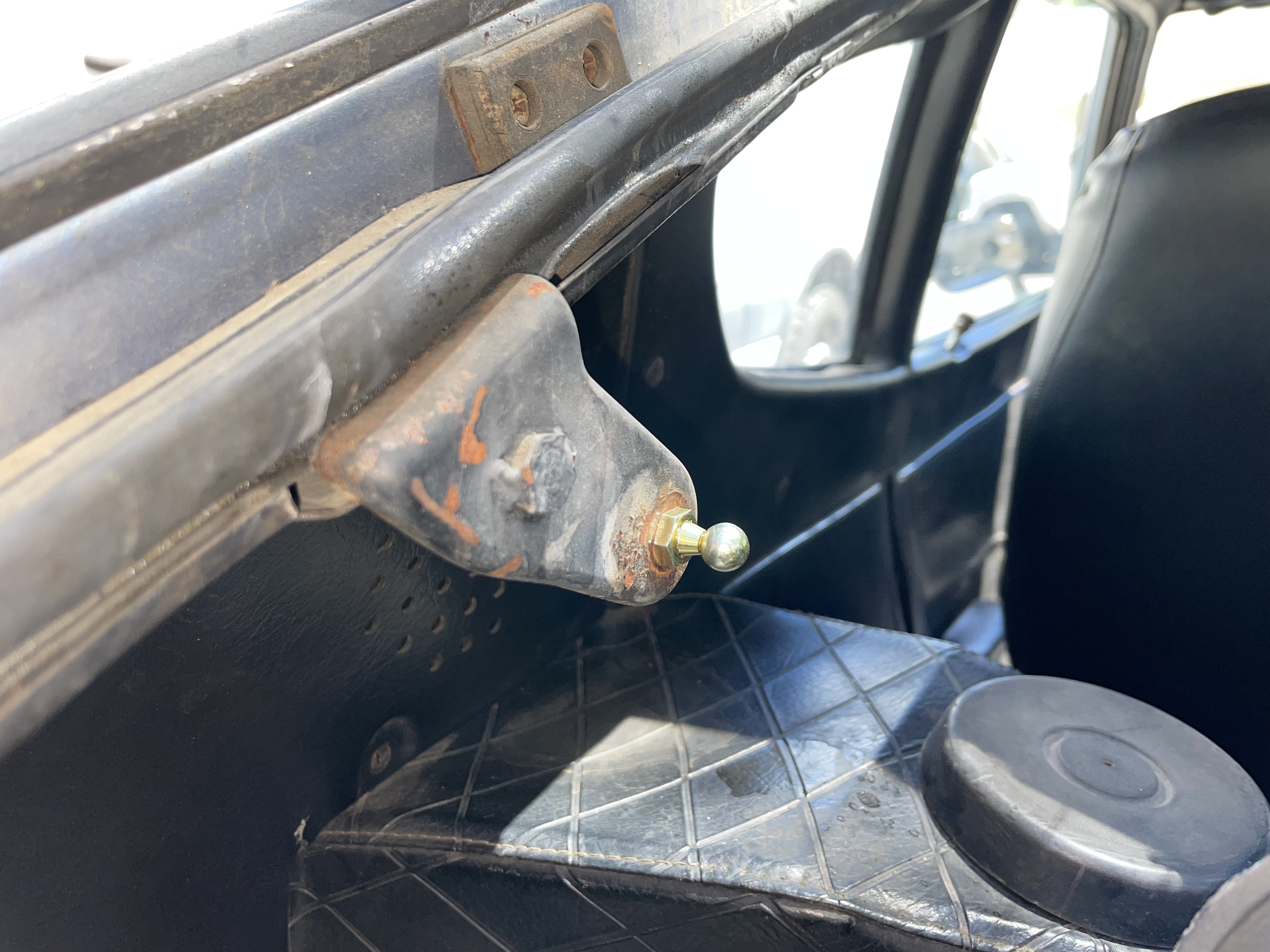
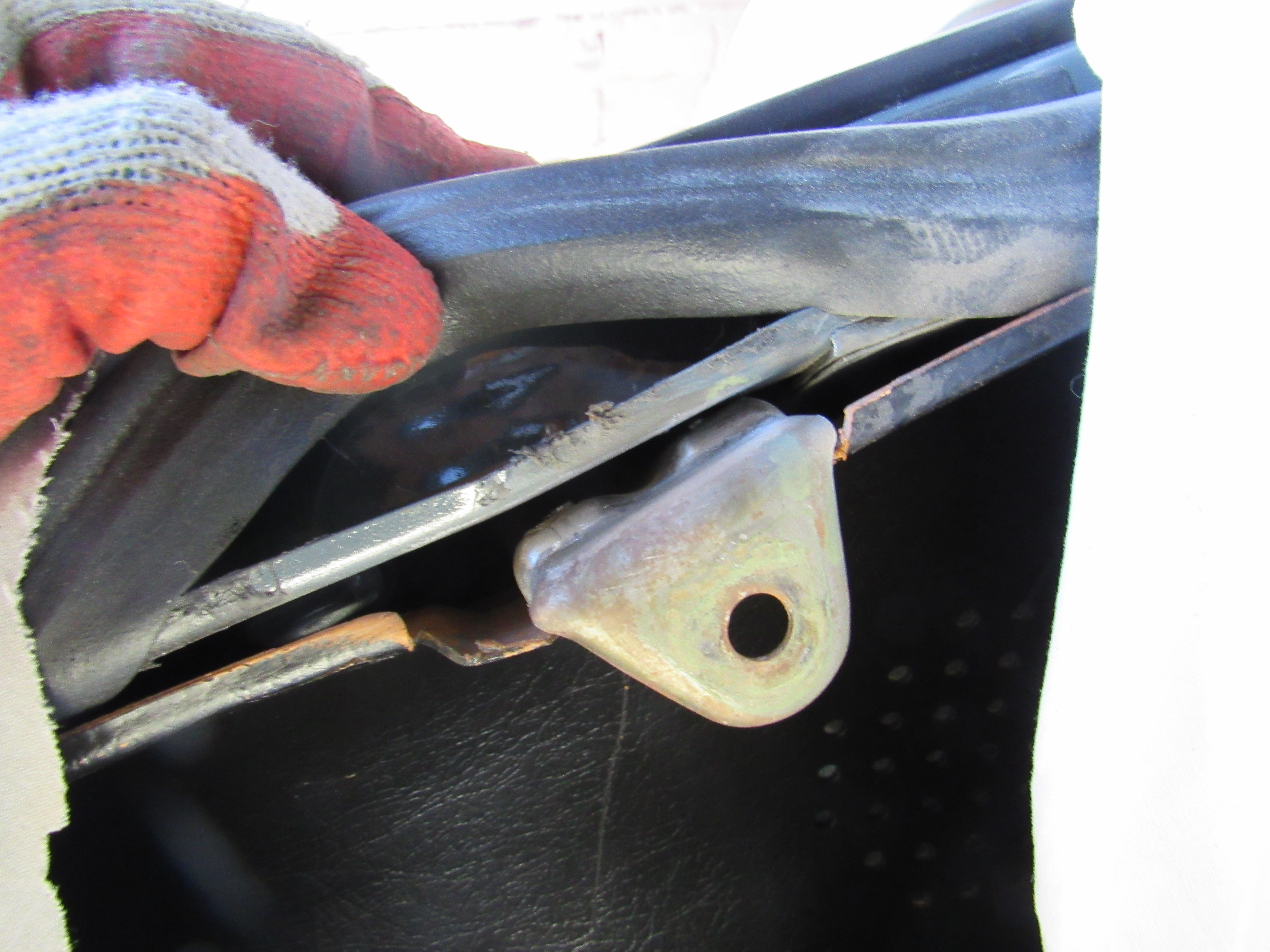
 1 pointOne of the possible drawbacks of the 90lbs of force or the 4313 cartridge is it requires more closing force than the original lift and at least in my case resulted in the lift support on the body being pushed away and bending. Had to strip the area down and re-weld that support, now the support on my car could have just been weak or poorly welded from the factory, I don't know but for the one lift early cars maybe a 70-80lb lift should be considered.
 1 point
 -
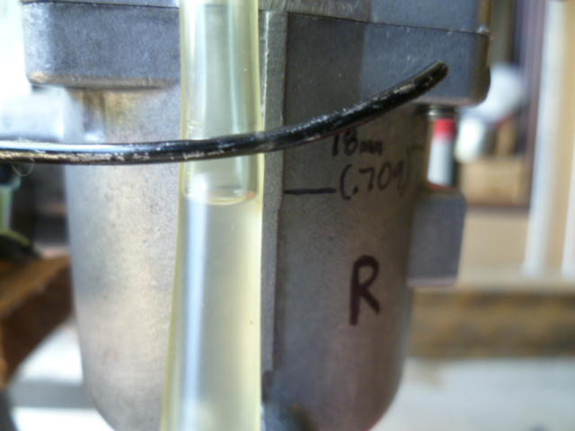
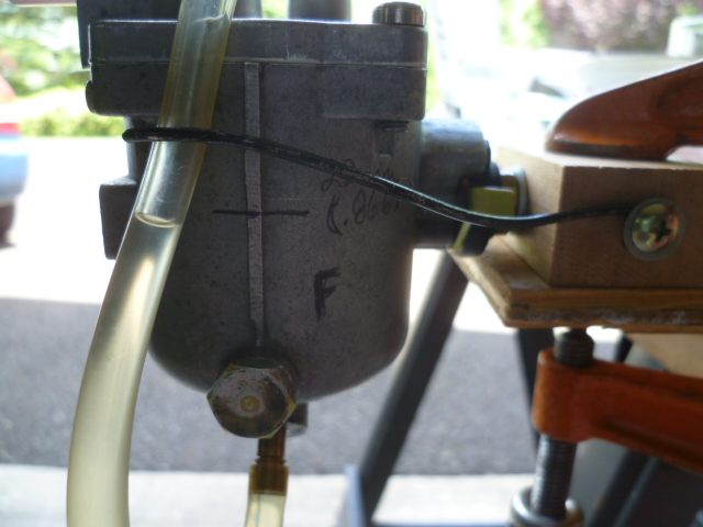
 1 pointAnd just to make sure that my "in a glass" test method was valid, I tested again using the more traditional method with a piece of clear tube off the fuel nipple at the bottom of the bowls. Here's my rig: Here's the result for the rear bowl:: I did have a WTF moment with the front bowl... I put the fuel in, and it overflowed. I discovered that the float was stuck against the bottom of the bowl casting. Yet another fantastic feature of the long ear 72 design. So I emptied it and refilled while tapping on the bowl with a plastic screwdriver handle. That dislodged the float, and here's the result:
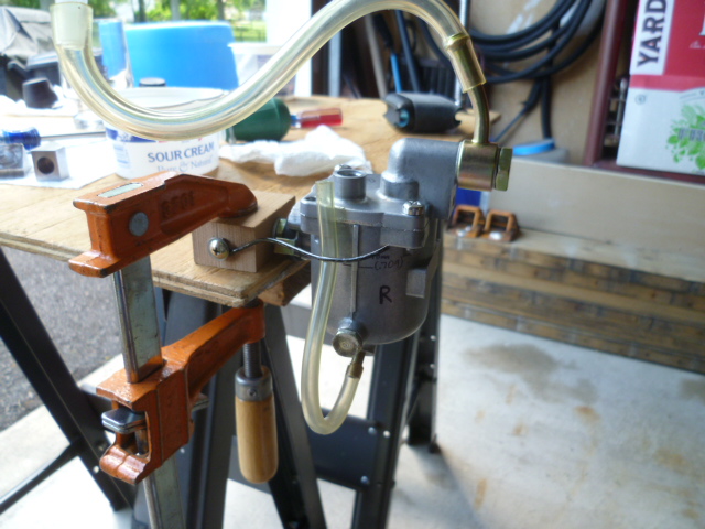
 1 point
 -
 1 pointHe had it in highschool so idk if or what is in his name and this was before he met his now wife so she wouldn’t have that. He has most of the paperwork for cars going back to the late 70’s till now, has a whole folder in his cabinet dedicated to his bricklin, mustangs. He even still has his first car 1960 thunderbird with 11k miles and has everything down to light bulbs just not the Datsun for some reason1 point
 -
 1 pointIt’s an interesting dynamic watching dual widebands with these plenums. Mixture varies with vacuum changes . I don’t use a dedicated grinder either . I might get serious and buy one just for that . Maybe a mini that sits on the welding table. I’ve got enough strokes against with skill level, so maybe clean consumables might help me . Burned a quarter inch hole already and was able to refill it - lol. The tig is slower , but is better if I can get it done .1 point
 -
 1 pointNormal vacuum at idle will pull oil into the combustion chamber due to a compromised valve stem seal. At higher revs, it tends to seal a bit better, or a bit more.1 point
 -
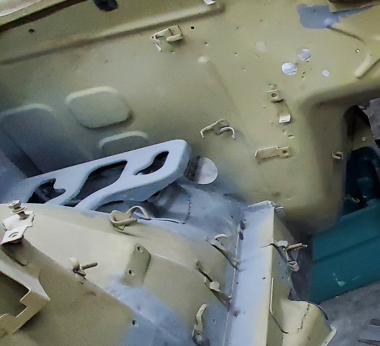
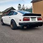
The diff mount seems to be sitting high. Look up in this hole and see if there is a nut on the threaded stud. Stole from Namerow.
 1 point
 -
1 point
-
 1 pointAnother small improvement for when you assenmle the transmission. On the top rear of the extension housing is the locating pin/circlip for the striking rod. It is actually located on the oil side of the O-Ring seal on the striking rod. It can weep oil. It is not much, but a little sealant around the pin (32847) and its circlip will stop it and keep the area dry and clean.
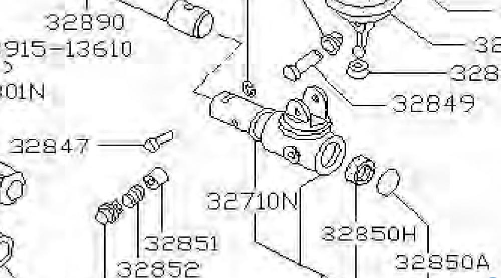 1 point
 -
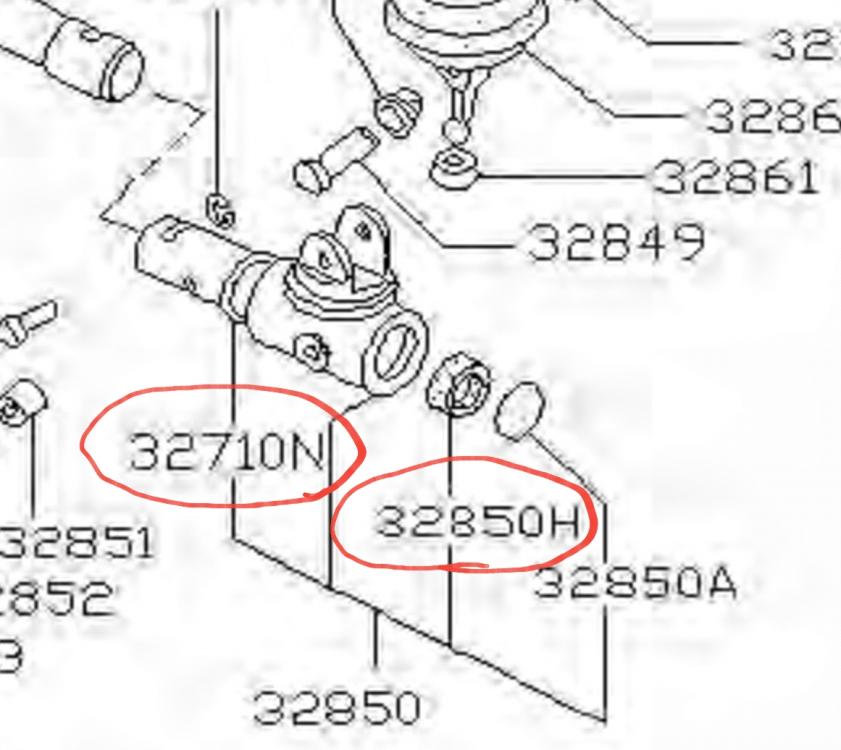
1 pointFor the selector seals you will need the o-ring on the outside of the striking rod (32721N) P/N:32710-14600 size:24x2.5mm and The inner lip-seal for the striking rod (32850H) P/N: 32858-U6702 size:14/20x2mm. You will need to push the cap off using the striking rod. It will come off easily and can be re-staked with little problem. You can use a tiny amount of sealant to create a god seal. The omega bush can be fitted in both directions. The hole is not used in the datsun extension housing.
 1 point
 -
1 pointI've always called it loading up. Fuel/oil gets by idling but burns off at higher rpm. Boats are bad about doing that.1 point
-
1 pointThe simple answer is, one of the valve seals (I'd guess the intake valve seal) #4 cylinder is leaking. The surface of the seal that rides on the valve stem is damaged, probably during installation. That allows oil to run down the valve stem and get sucked (intake valve) into that cylinder.1 point
-
 1 pointOk. Question: why does it gets oily and dark when the car is idling for long periods while the other dont?1 point
 -
1 pointIf it was mine, I'd start with removing the #4 valve seal and inspect it for damage. I suspect it was compromised during installation. Swapping out the other seals depends on what you find and the desire to do all of them.1 point
-
1 pointThe only thing the shape of the float submerged matters much. I would theorize that you want the tapered nose because it would more gradually slope the pressure on the valve up and also not allow any trapped bubbles stuck under the float. But other than stuff like that, I can't see it mattering much. The problem is, as you mentioned, denser fuel will cause the float to sit higher. A higher float causes the valve to close sooner, and a valve that closes sooner results in a lower level in the bowl. And the issue is that I've had troubles getting the level high enough without the float actually hitting the underside of the lid. You remember this discussion you and I had almost ten years ago? I think this was all related to this same issue: https://www.classiczcars.com/forums/topic/43889-fuel-bowl-level-and-bending-tab-not-working/1 point