Leaderboard
-
kats
Free Member4Points2,209Posts -

RabbitZ
Free Member3Points434Posts -

87mj
Free Member3Points368Posts -

Barefootdan
Free Member3Points275Posts
Popular Content
Showing content with the highest reputation on 02/13/2022 in all areas
-
3 pointsYou can set your paypal account up to point to a checking account or a credit card. Mine only points to a credit card. If I ever have a discrepancy such as this, I dont bother contacting Paypal. I just dispute it with my credit card company. I always win. Either I received the stuff or I didnt. Several years ago, I restored my Jeep Comanche pickup. My factory rims were in bad shape and I found a place online somewhere that had 4 of them. I bought them. What I didnt realize was they found several rims throughout the country and sent them to me. They each looked good but they didnt match. The tint of the clearcoat was way off. It was very noticable. I contacted the company I bought them from, and this woman told me I didnt buy a set of rims. I bought 4 rims. After a few phone calls, emails and photos, they dug their heals in and wouldnt let me send them back. I contacted the credit card company and about 6 weeks later, I received an RMA in my email. If you used a credit card, contact the card company directly. Even though you specified family or friends, there is still an email paper trail. Credit card would back that scam up in a minute. I love boinking scammers like that.3 points
-
3 pointsThe wiring project is finally coming to a close. I’d argue that this took more work and effort than the engine rebuild and I would definitely rather rebuild an engine than another wiring harness 🙂 I envisioned that when I designed my own wiring harness digitally, it would make the whole process much faster, and in a way it did, but not how I imagined. What I learned by drawing out my own harness was more informational. I learned how everything worked, I became familiar with the OEM harness in both identification and functionality, and I may have gone a little crazy tracing black and white lines for hours on end. So going into this project I knew what I wanted to remove, what I wanted to replace, and what I wanted to add. I had the new diagram printed out in a 2x4ft poster for the garage and was ready to use this as my guide, but in all honesty, I probably looked at that poster 5 times in total. Once I started the actual wiring, it was far easier to do a combination of tracing OEM wires and using the OEM diagram. I still needed to find the correct length of each wire, so I needed the OEM harness with me anyways. This was also my first electrical dive into the car world, so I wanted to use the OEM diagram to ensure all circuits were correctly terminated. I think someone who is more confident in their wiring capabilities, and knows all lengths of wire (at least the minimum length needed) could use a self drafted diagram only. It just didn’t work for me. Now, enough boring talk, let's dive into what I used, how I used it, and what's next! Parts used: It was a bit of a pain sourcing electrical items with the current COVID supply chain issues. I knew I wanted to use 280 series fuse and relays for everything. I can't stand the look of regular sized relays, let alone 6 of them side-by-side. I also knew that I wanted to update all original relays and connectors to modern technology. Originally, I wanted to use a Bussman Distribution Block: This was my first choice since you can neatly organize your relays on the left, fuses on the right, and choose if you want busbars integrated or not. Unfortunately it was tough to find what I wanted in stock and I knew I would need a minimum of two to fit the amount of relays and power sources I needed. So I ended up using a GEP Distribution Block: The GEP block is similar in that it allows for 280 series terminals but allows for more flexibility in placement. The downside is there are no busbars so you will need external setups for your power in and ground.But it was available, so I can't complain! I picked up two generic busbars that had covers to hide most of the mess. It would have been so nice to just run one power wire though, via the Busmann Box. I paired this with 280 series relays, the simple 4 pin relay we all know, just smaller form factor. Do note, that while this is a 4 pin relay, it occupies a 2x3 portion of the distribution block. Still, I was able to fit all relays and all circuits in this 96 pin block with room to spare. Make sure the relays you order are for 12V and not 24V and rated for the amperage you need…I may have ordered up the wrong set initially. Next was my relay for the main power. I used an 85 amp weatherproof solenoid. Same function as the smaller ones above, just heavy duty as this is is handling all power to the car (minus the start motor): The circuit breaker I chose is okay. It feels cheap but is rated at 120 amps and is “waterproof”. We’ll see how long this lasts but I don't mind changing this out in the near future for something closer to the 85 amps of the solenoid. For now, it works and is a nice extra layer of safety: I was going back and forth on connectors for a while. Deutsch style, AMP style, Weatherpack style, there were so many choices and everyone has an opinion on this. Pick what you like, anything is better than 45 year old plastic at this point. I chose weatherpack because it was easy to source and the crimping tools did not cost me hundreds of dollars (I'm looking at you Deutsch….). Funny enough, I don’t think I would recommend weatherpack if you’re doing a full harness. Or at least not only weatherpack. I used the Metri-Pack (APTIV) 280 series. And while yes it worked just fine, I didn’t like how limiting this series was. With a 6 pin connector max that was a 1x6 setup, I constantly found myself wanting 8,10,12, even 14 pin connectors to clean up the look. Luckily they do have a Metri-Pack GT 280 series that is a much more modern design with connectors up to 16 pins. There are some amazing bulkhead connectors out there as well, but it wasn’t in the budget at the time. Don’t cheap out on the terminals and seals. I bought a pack off Amazon as I was short a few, but the metal is so much worse. The knock off connectors I found to be a decent copy but with slightly worse tolerances. I used these as a last resort. Lastly, the wires I used were a GXL rated wire. I picked up a pack of 18 gauge, 12 gauge, and 4 gauge for my battery leads. I would probably swap the 12 gauge for 14 gauge next time. So, we have all of the supplies, a plan, and LOTS of time to work…let's get started. I started by bringing the OEM harness to my “workshop”, aka my kitchen, and taped off connectors I knew I didn't need. Things like Air Condition, excess relays, emissions, interlock, etc. I then started with the longest wires and traced them with my new GXL wire for length. I labeled each wire to keep things documented. I only used 11 different colors and rarely had issues with micing up cables. I tried to logically use them so no two same colored wires went to a similar spot or into one connector. Once a connection was complete, I would tape the old connector as well to let me know I finished. Doing the tracing took me a full evening for the engine side. I then tackled the dash and body. My connectors here on the OEM harness weren't bad so I decided to keep the original setup and splice my two setups together. Looking back, this worked just fine for the body harness but I wasn't a fan of doing this for the dash. The dash wiring gave me more headaches than the engine bay and body harness combined. Anyways, once my harness was laid out, I wanted to toss it in the car to see if my lengths were accurate and to give me a visual aid if I missed any wires: Everything fit perfectly and erred on the long side which I was happy with. So I could start the terminating process! Does that make me The Terminator?! This took the most time and definitely was the most tedious. Each wire needs a weather seal and pin lined up in the crimper. It was also overwhelming on where to start. I have this huge mess of wires and was lost on “Do I start with the power side, or the accessory side?” I wanted to follow the flow of the current so I ended up with the power side. I mapped out my distribution block and just started one by one. It was easy to get lost in the wires but just do one circuit at a time. Each lead off the distribution block had about 10-12” of wire which would then terminate to a weatherpack connector. I would then match this with a connector at the start of my harness and connect the two once complete. I did not terminate the accessory side of the harness yet so I could trim the wire to the length needed once in the engine bay. About 15 connectors later I am ready to start testing this spaghetti, mama mia! I immediately ran into a couple issues that I would highly recommend people do differently! First, as soon as I layed the harness in the car, I saw my absolute abundance of connectors under the dash. Was it functional, absolutely. But it was just a disaster there and I bet driving down the road would sound like a toy bin with all the connectors bouncing into each other. So I ended up ordering a pack of 12 pin connectors that would consolidate my setup. I used a 12 pin for the distribution block to the engine bay, and another from the distribution block to the dash. I do have a few weatherpacks thrown in for the body harness for my 12 gauge wires. The other issue I had was with my distribution block location. I knew I wanted to use the original fuse box spot, but when I did my wiring, I didn’t have exact lengths for everything (Block to busbars, block to harness, etc). I would suggest people tackling this to make their mounting plate first, then start your terminating. I had to shorten everything after I made my plate, oops! Once we settled that, I could start running my main power. I ran 4 gauge wire from my battery to a 125 amp breaker. From there, we travel to the 85 amp solenoid. This is triggered by a master kill switch on my switch panel that always sees 12V (through a fuse). This will finally feed power to my distribution block. I didn’t want to hack up the original mounting plates so I used existing holes and I am satisfied with how it came out. I would prefer the breaker to be hidden but I can always move it in the future. So I have power now and the testing can begin. I started with simple circuits like my fan relay, starter relay, etc. I created a spreadsheet that lists all circuits and if they were functional yet. In my previous posts, you will see that I ran into a couple hiccups along the way but nothing major. I can't tell you how many times I wasted 20 minutes or so diagnosing a circuit when either the main harness wasn't even connected or my power switch was off! Too many things going on in my head and I lost track of what was done. I mean c'mon, this looks organized right? …right?! What a mess!! It looks worse now than when we started. But I promise it works! And I promise not to shove it up under the dash as is 😄 There are a few items left to still test, but I cant before the engine is hooked up to the new carburetors. Things like oil pressure, alternator, tachometer, etc. I feel confident enough now to start looming my harness and wow what a difference this makes. The harness now comes back out again to get a last review to make sure all of my splices are sealed and nothing is mangled up. In my spreadsheet, I updated all of my notes to match what color wire I used, where it is pinned, and when it sees power. This changed a couple times during my testing so I am glad I did this step last. I used this split loom in various sizes to wrap. It was very nice to use and allowed for T-offs very easily. This was also nice to use since I didn’t need to remove my connectors to wrap. Each end was also taped up with some fabric tape just to ensure nothing would shift around or unravel. I grabbed a firewall boot to help keep the elements out as well. Here is the final product, a fresh harness! I am so pleased with how this turned out. I hope this helps you guys with any wiring projects you run into. Feel free to ask questions about specifics like what pins I used, what tools, quantities, prices, etc. But this post is already mega long so I spared you the details 🙂 But now what? The carburetors are getting dismantled for the ultrasonic cleaner, and rebuild kits are ordered up. Once every circuit is finalized I will move my way to the interior, finally!3 points
-
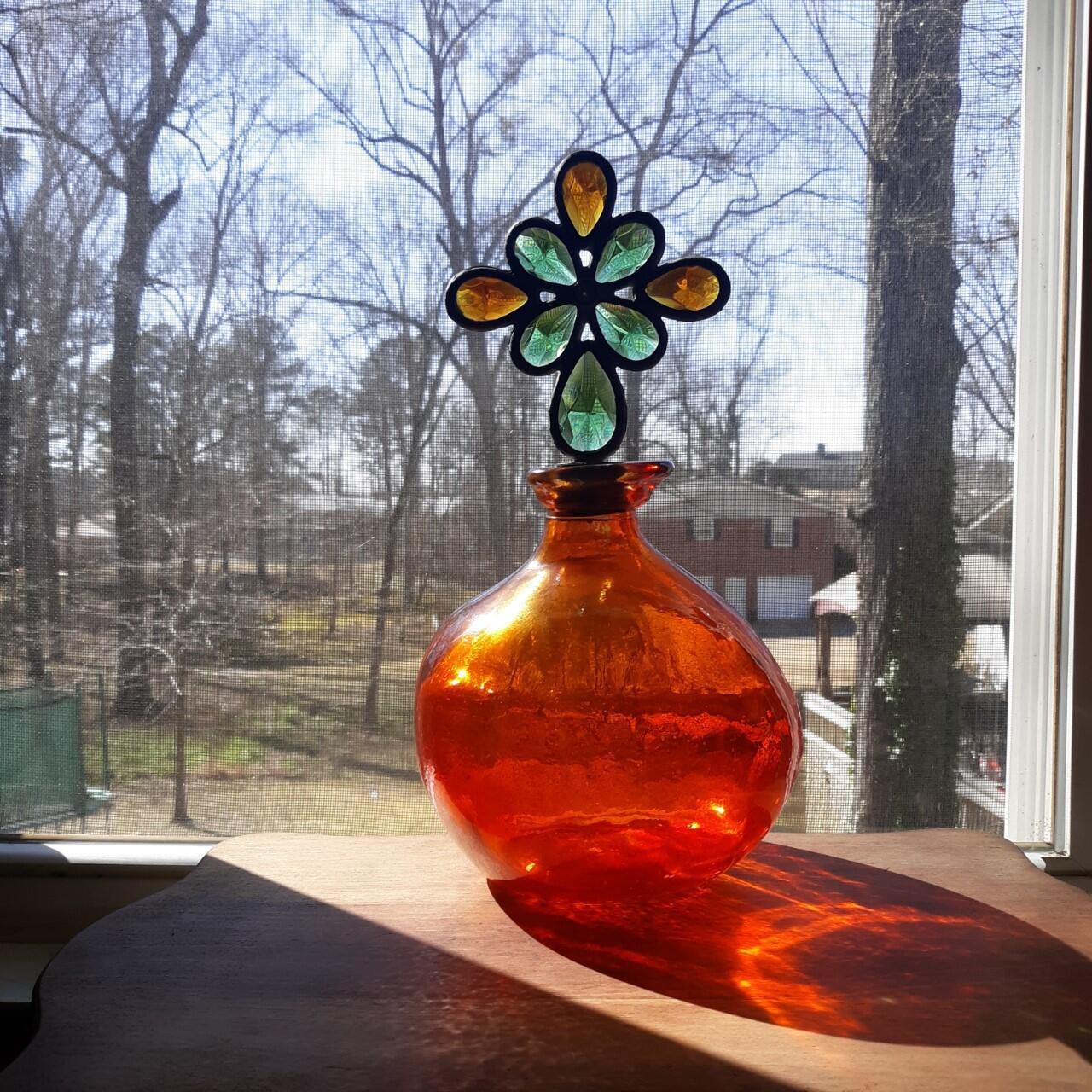
 2 pointsI know it's a car club but I'm a Southerner. When it gets cold we stay inside. This makes me smile. I made it out of an old stain glass wine stopper and a vase I bought at a yard sale. Inside down time is hard for me. I hope you others are not suffering "cabin fever". It's a tough problem for compulsive people like me. Bengals by 10.
 2 points
 -
 2 pointsCliff, it looks like winter at your house. It's currently 87º here today with a wind chill of 89. While you're watching the game today, pay attention to the BMW commercial that will play during the first quarter. It stars Arnold Schwarzenegger as Zeus and Salma Hayek as his wife. The golf course scene was filmed in my neighborhood. :2 points
 -
 2 pointsI haven't read through your entire post yet, but what I have is most impressive. This is particularly exciting for me as I am planning the very same course of action. The detail and commentary you've provided will be most helpful. Very nicely done, sir.2 points
 -
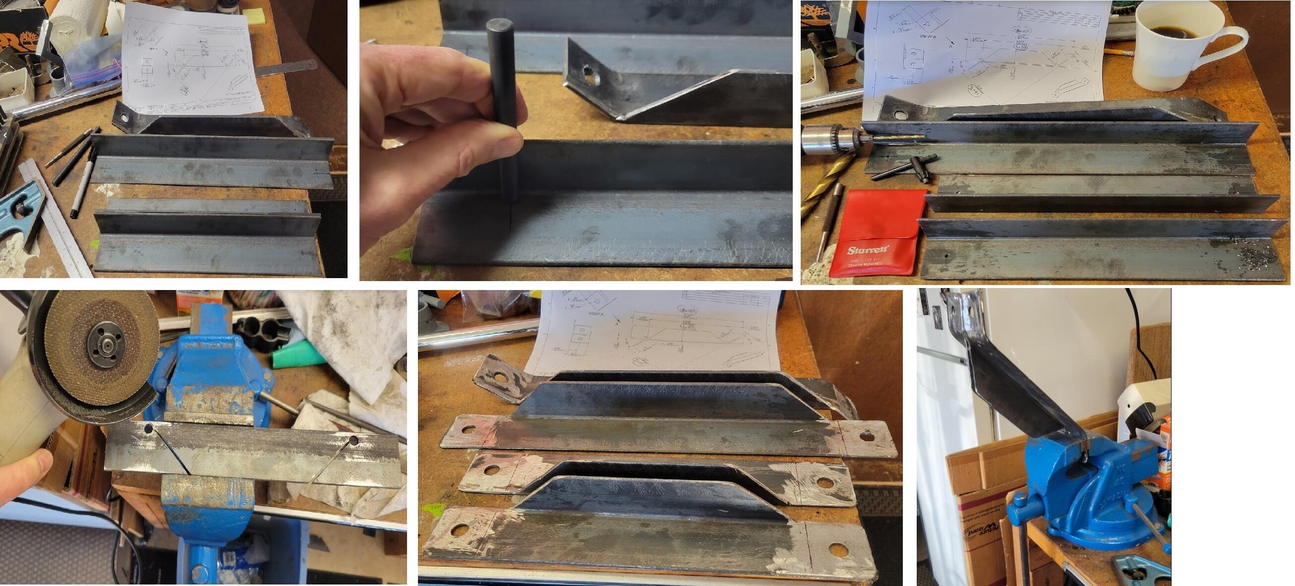
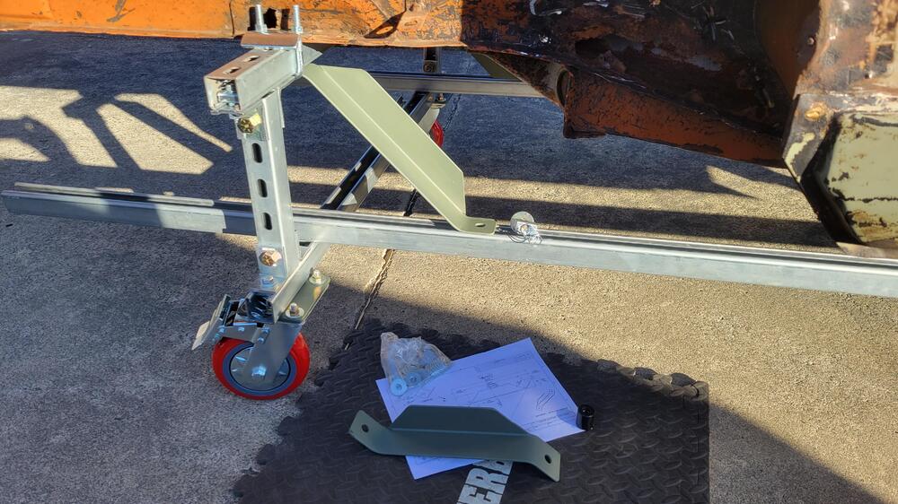
 2 pointsYesterday I made and installed four diagonal braces to complete my rolling chassis support. Deb, my better half, has renamed it "The Two Forty A La Carte". In keeping with my no welding theme, the braces are simple angle iron parts, cut/drilled/formed and then bolted in using Unistrut channel nuts. I don't have much experience making parts like this and it was enjoyable to practice some basic techniques.
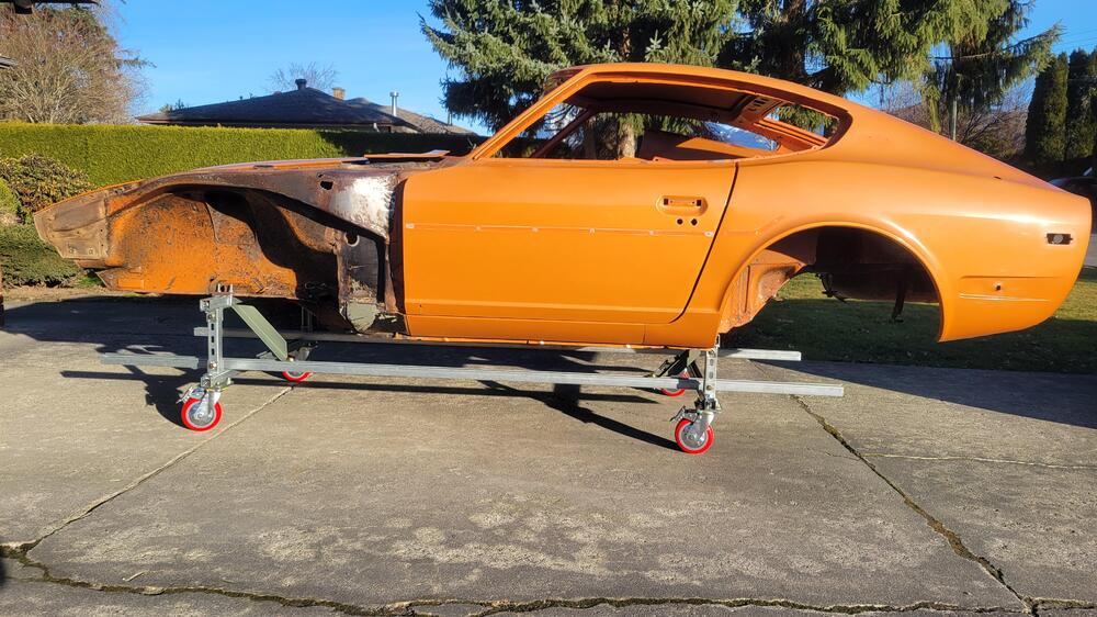
 2 points
 -
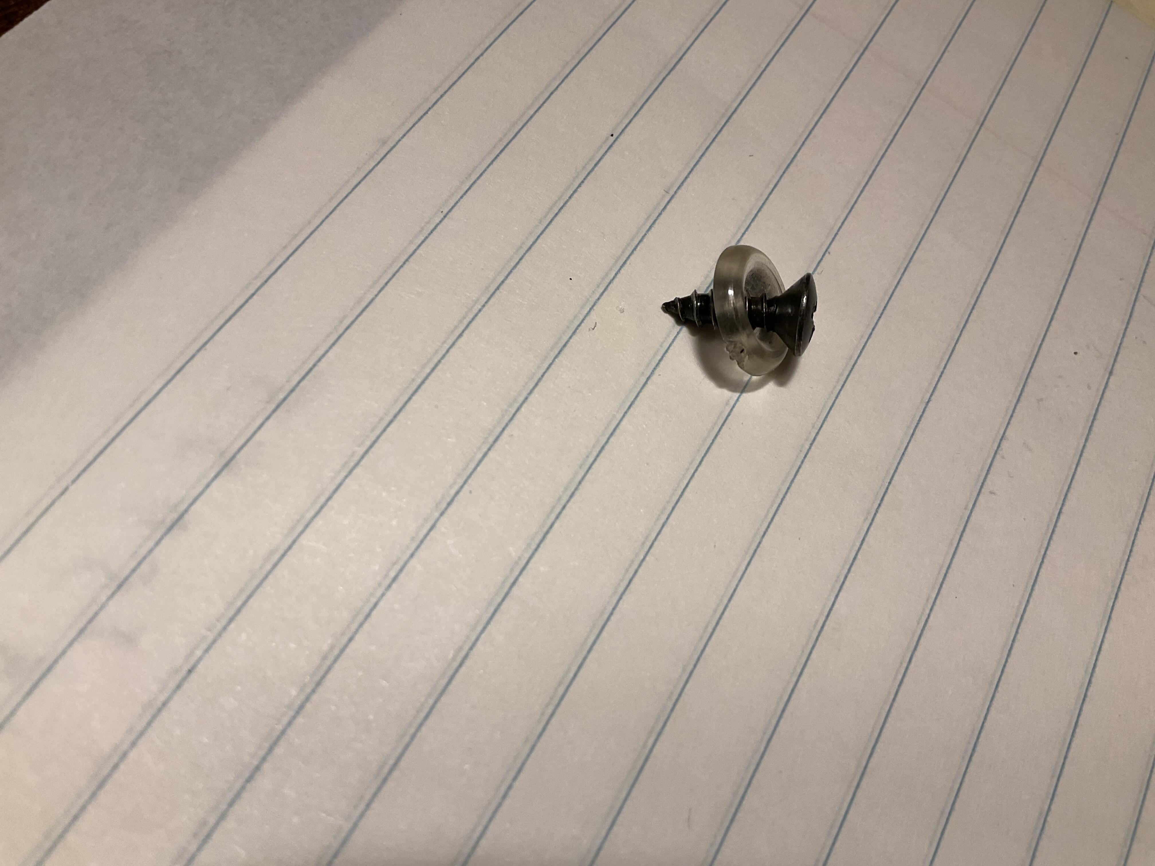
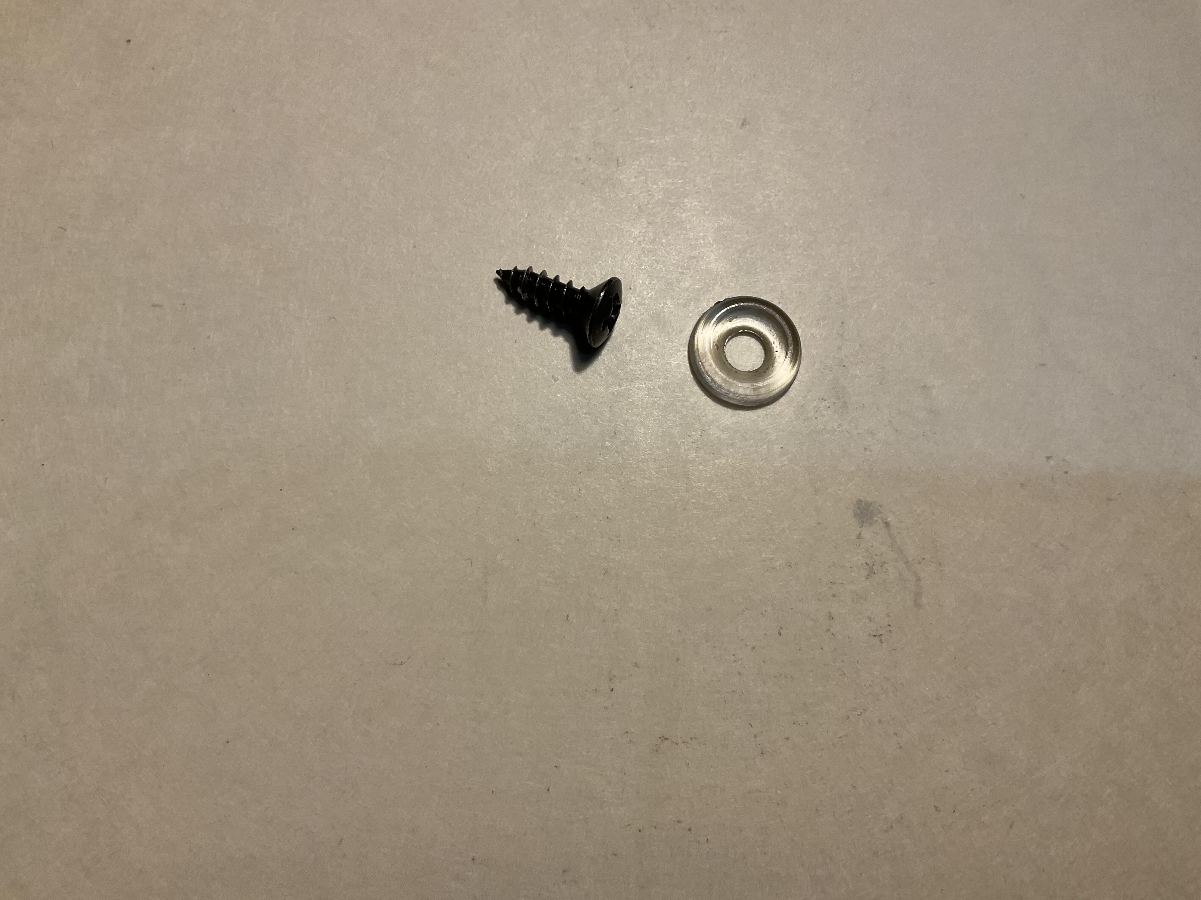
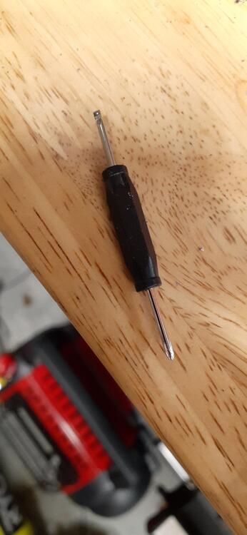
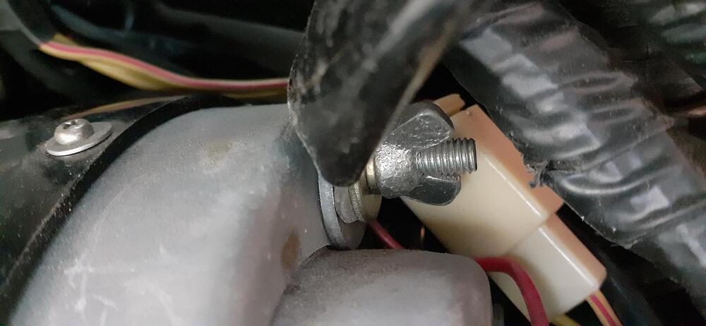
 2 pointsDave, I have a 1971 series 1 car, so not sure if what I have would be the same for your 280z. the original trim screw for my car is a black oxide, self tapping, oval head Philips screw. The finish washer is a clear plastic rounded, or dished washer. The screw measures approx 9mm of thread length with a total length of approx 13mm. See photos below. Hope this is what you are looking for.
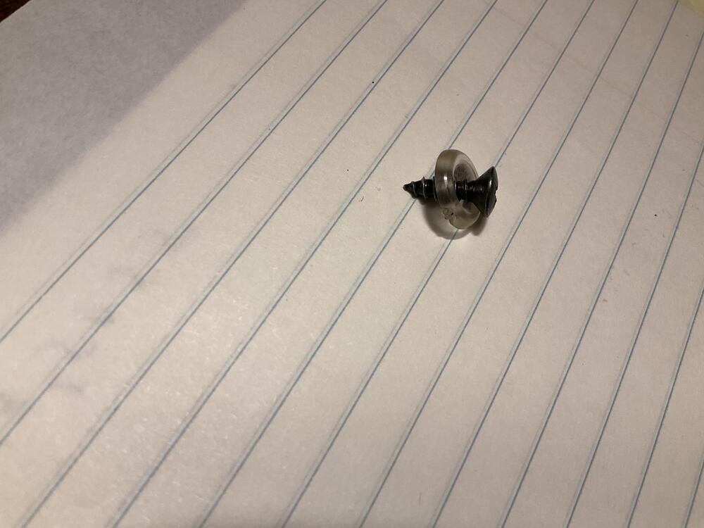
 2 points
 -
 2 pointsDid you need the whole pedal box with the two pedals? most of the actual boxes are set up for auto or manual applications. Normally you would just need the two pedals, springs, and mounting bolts. Not sure of your situation. I think I still have a set if you're interested. Size and weight make up the freight price. Taxes are usually on your end when you pick it up. Sorry to hear of another scammer, they seem to be coming out of the woodwork in the classic car world. I am sure they are all over the place when there is need for goods. If you sent as Goods and Services PayPal should cover you. Friends and family is always a risk.2 points
 -
 1 point
 -
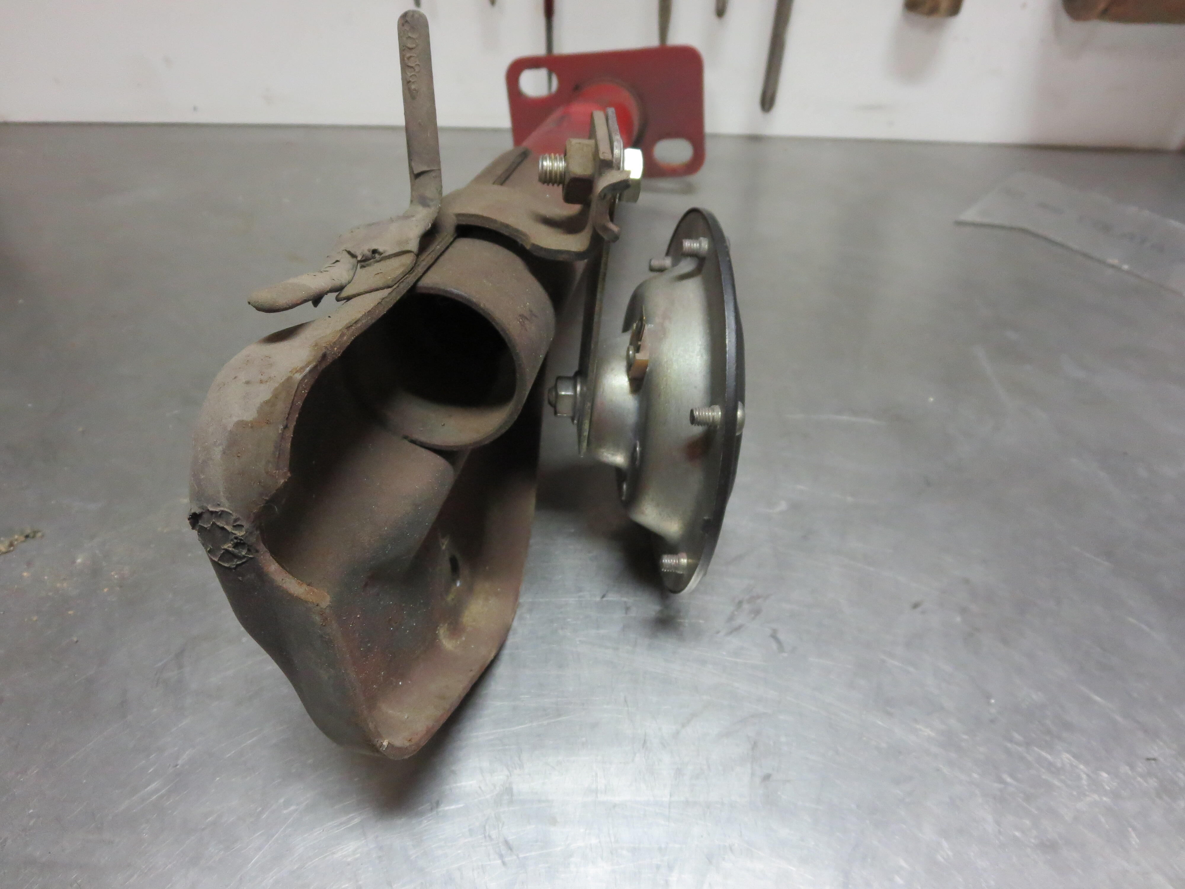
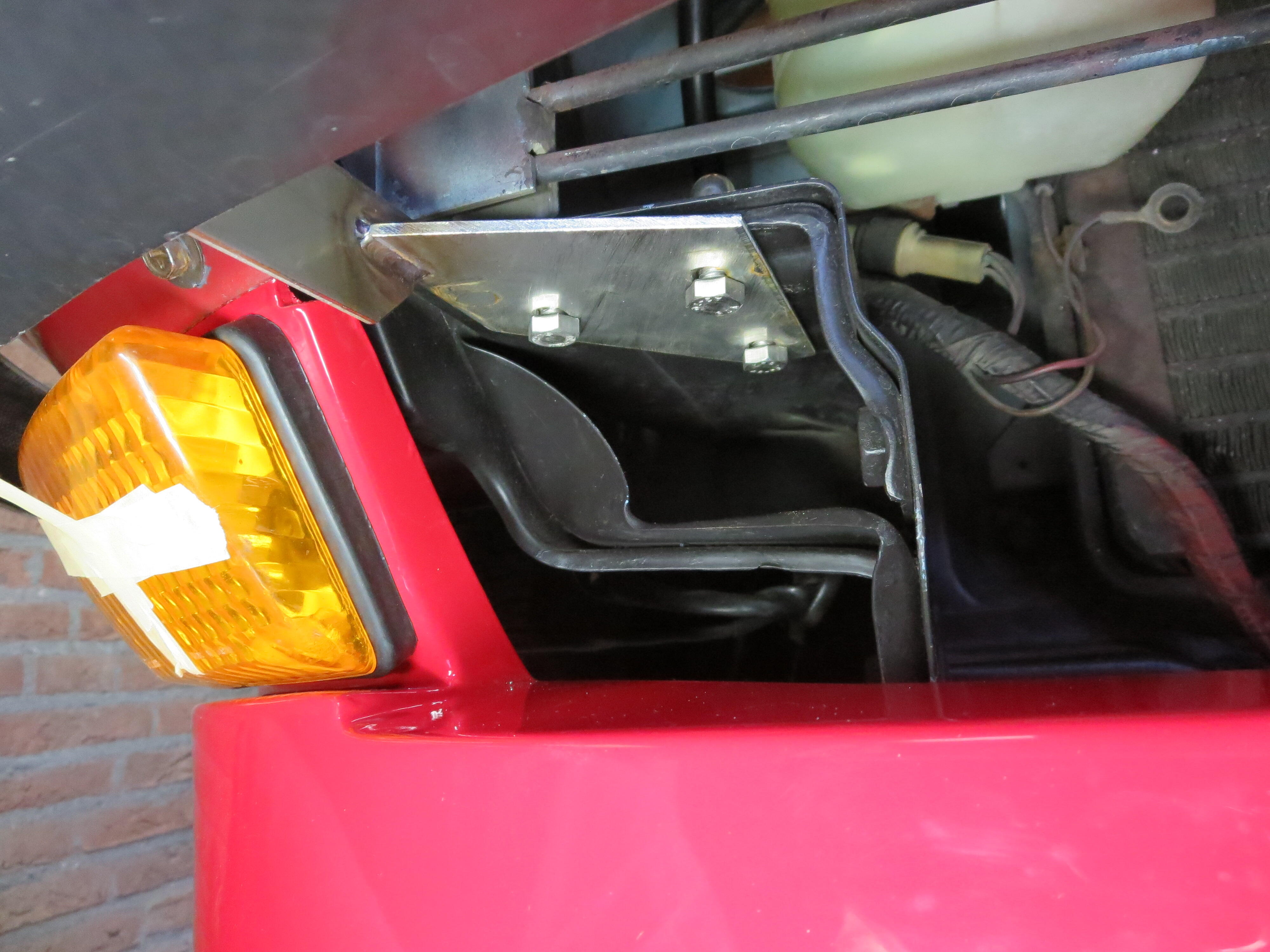
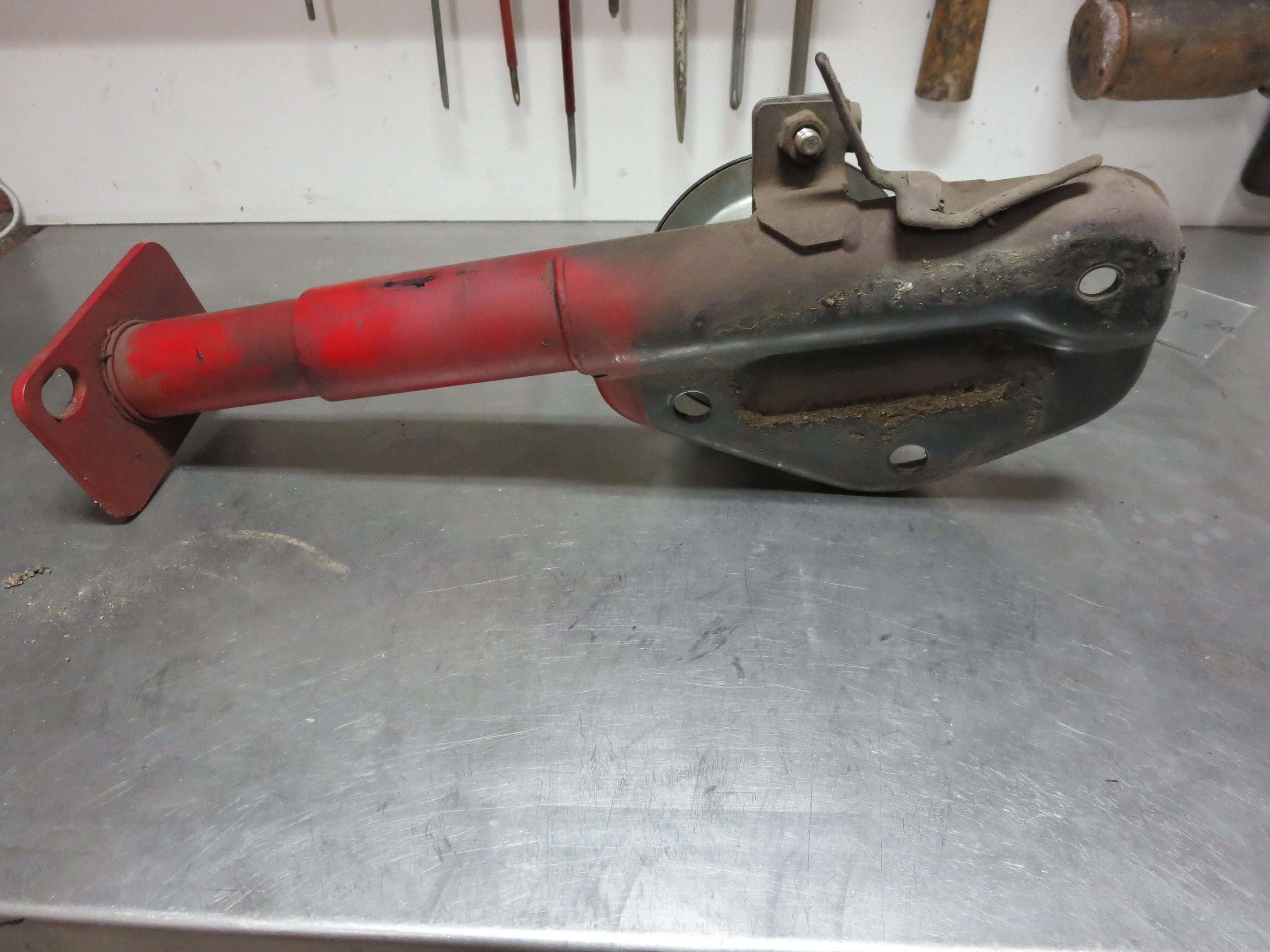
 1 pointFound some photos I made for someone wanting photos of the horn mounting position.

 1 point
 -
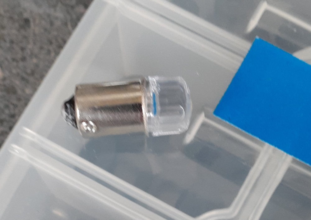
 1 pointI took the Z out for a drive today since I wasn't able to yesterday. Two steps (minor) back. I could see a long gap between the window frame and the door seal on the driver's side. I am thinking that a 12.7 mm bulb on the door seal would be better. The ones I tried were only 9.5 mm. I found the 1157 bulbs in front and back failed and were cross-feeding. I was seeing signs of that last night, but I realized the problem and confirmed my diagnosis today. New 1157 bulbs are on order front & rear. What were the symptoms I saw? Well, first, I saw the heater panel illuminate with the turn signals. I thought it was just stray light. Then I noticed the same thing happening with the brakes. I removed both the front and rear bulbs from the driver side and tested the turn signal on that side. The cross-feed was gone. (And, yes, these were 1157 bulbs with 2 contacts and oriented properly.) I took one of the bulbs and a spare 1157 socket over to my power supply. When I applied power to the brake lamp circuit on the socket at around 13VDC, I could see 12 on the positive wire for the running light circuit. Dang Chinesium electronics! Anyway, I ordered some red 1157 made by the same company as the H4 LEDs I'm using. The new 1157 ambers are from another company since Auxito doesn't sell amber 1157 bulbs on Amazon.1 point
 -
1 pointIMark, If you need photos of the 77 bumper shacks, I can take as many as you need. I still have the old bumper and shocks, but no ends. Gave them to the Captain. Jai could have it all for free, but shipping would be out of this world.1 point
-
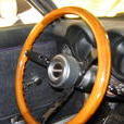
 When i got my "west germany" Spec turn signals last week, i went through my own parts to compare them, and realized i have everything ready to assemble a nice pair of restored ones. A perfect task for a saturday morning. so i got everything ready and started the project: From the three complete sets i have, i realize only one of the amber lenses was still without cracks: What a difference a little cleanup in warm soap water makes: Then i cleaned the rubberpieces and chrome trim with a bit of warm water too and had the rubber seals greased up with a bit of petroleum grease (Vaseline) and the chrome trim cleaned and polished with my secret weapon called "Metarex" And here we go, everything cleaned uo and assembled. looks like almost new. I will probably take one of the lenses from the "west germany" spec signals, as they're exactly the same. but until then, i just keep them as they are. Oh andi need new bulbs, the old ones are both quite corroded and i want some nice ones 🙂1 point
 -
1 pointAs said above if you linked the funds through a credit card, ask the card company. I get the impression you linked your bank. I will confirm I have the whole set of pedals, and send pictures for you to decide you would like to proceed with another set. No rush, take the time to give @mikegreen008 the opportunity to make this right for you. Refund or the parts. 54 days on the forum and no posts. @Mike should also be aware of this activity in my opinion. Good luck, as well.1 point
-
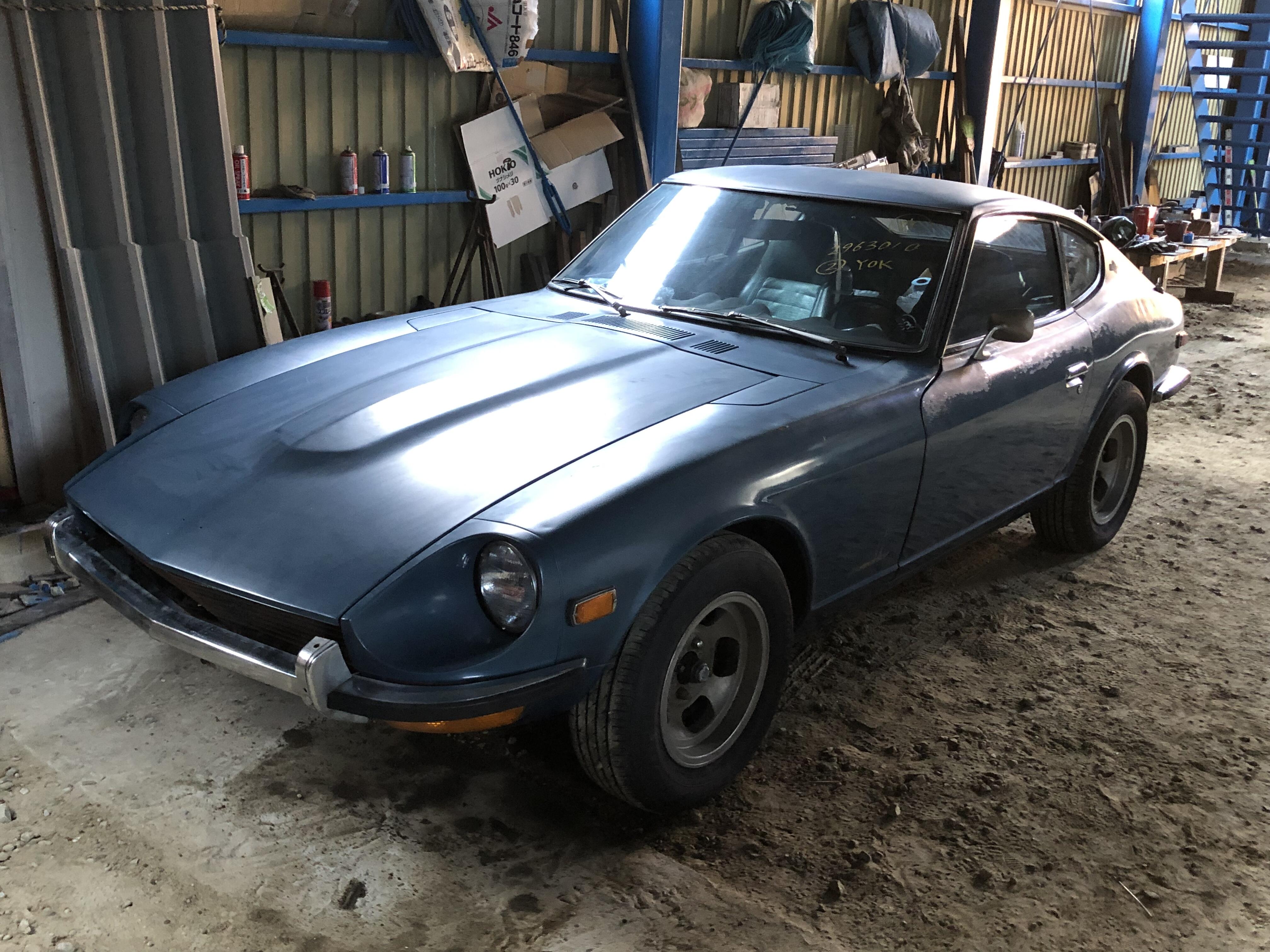
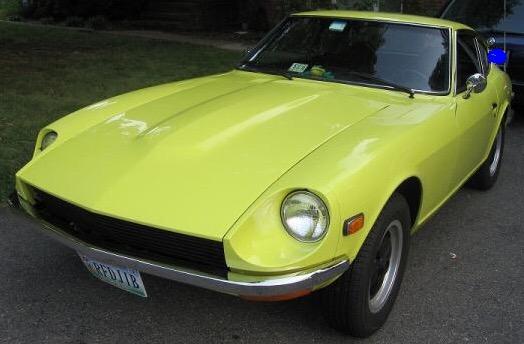
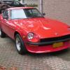
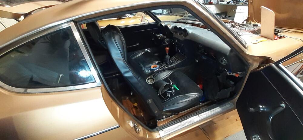
 1 pointHi Mark, yes it's a small world 🙂 ... If i could tell you what it's gonna cost just from a few pictures, i would have a job in no time that made me very rich haha.. I see a lot of strange damage on the car, some damage has white (bondo) under them.. so it will take a complete sand down and paintjob... what will cost you about 10 grand... euro's? Then there are no floor pics so we don't know... almost all need some tlc in the floor section.. The car has roundtops.. so the car was driven al lot i think... most of the mechanics are sloppy.. we simply can't know what the condition is.. Mark, you can see my resto of a very original dutch car 280zx slick roof but don't ask me what it costs.. At the moment i'm to ill to work on it but the engine is out.. last work is the engineroom.. the rest is ready.. 120tkm on the clock in 42 eh 43 years! I've got a 240z and a 300zxtt, the 240z is my wintercar.. looks like a pile of $^!#..haha but it's a ever lasting reliable car! And the 300zxtt is my summercar for 15 years and was never on the road in winter! It's almost like new, all winter "schorsingen" are with the car at the RDW!! Picture from the PO.. Here a link to my restoration.. nice read? If you want to call me some time just shoot me a PM and i give you my cell..
 1 point
 -
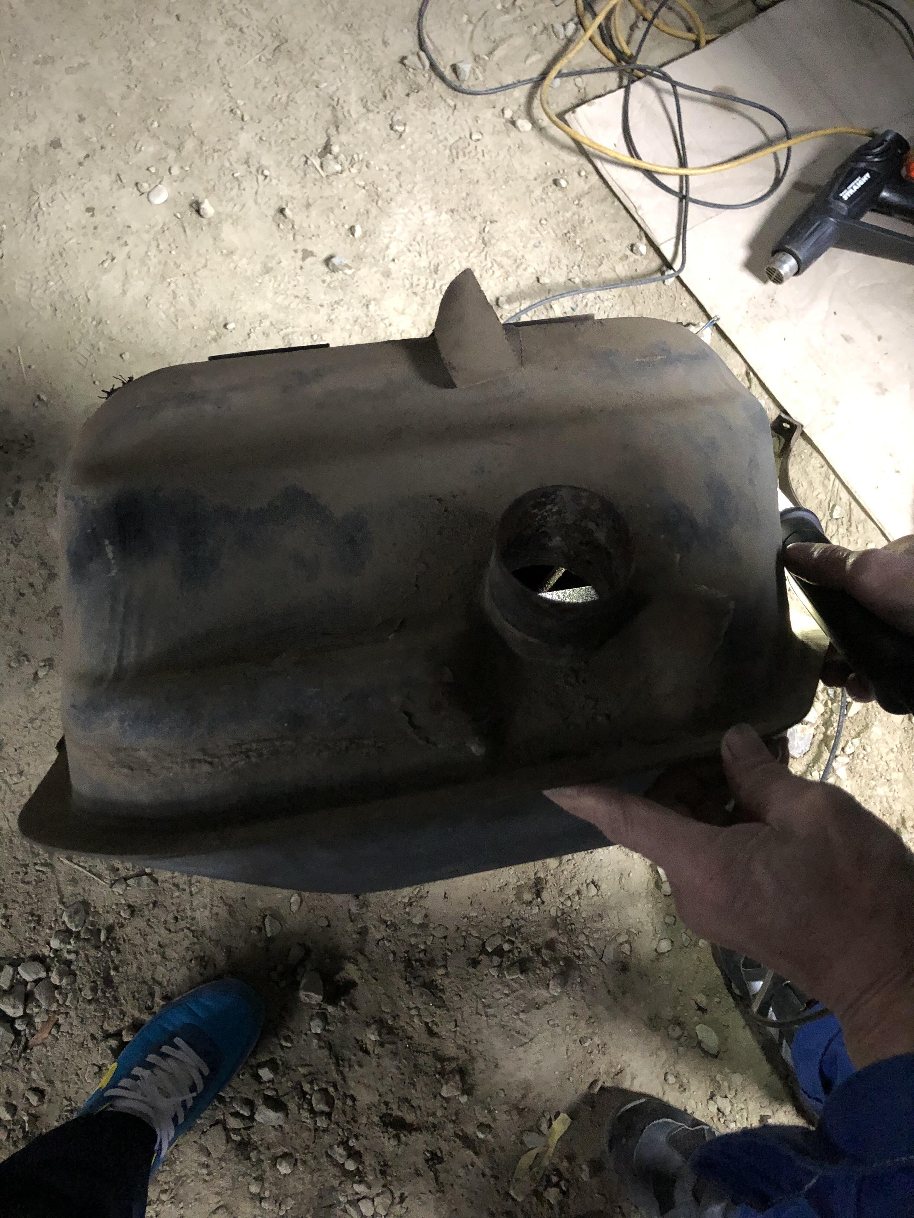
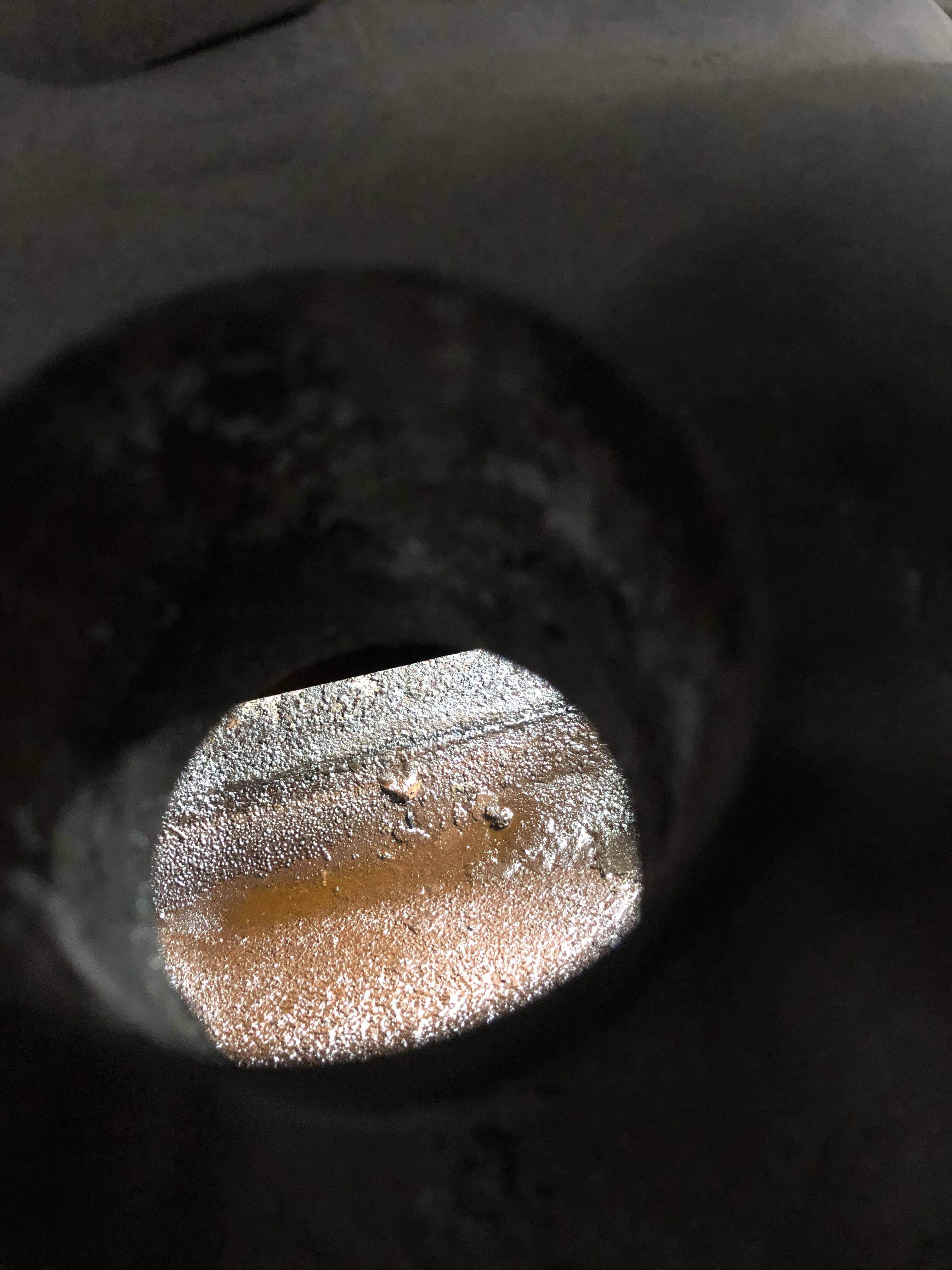
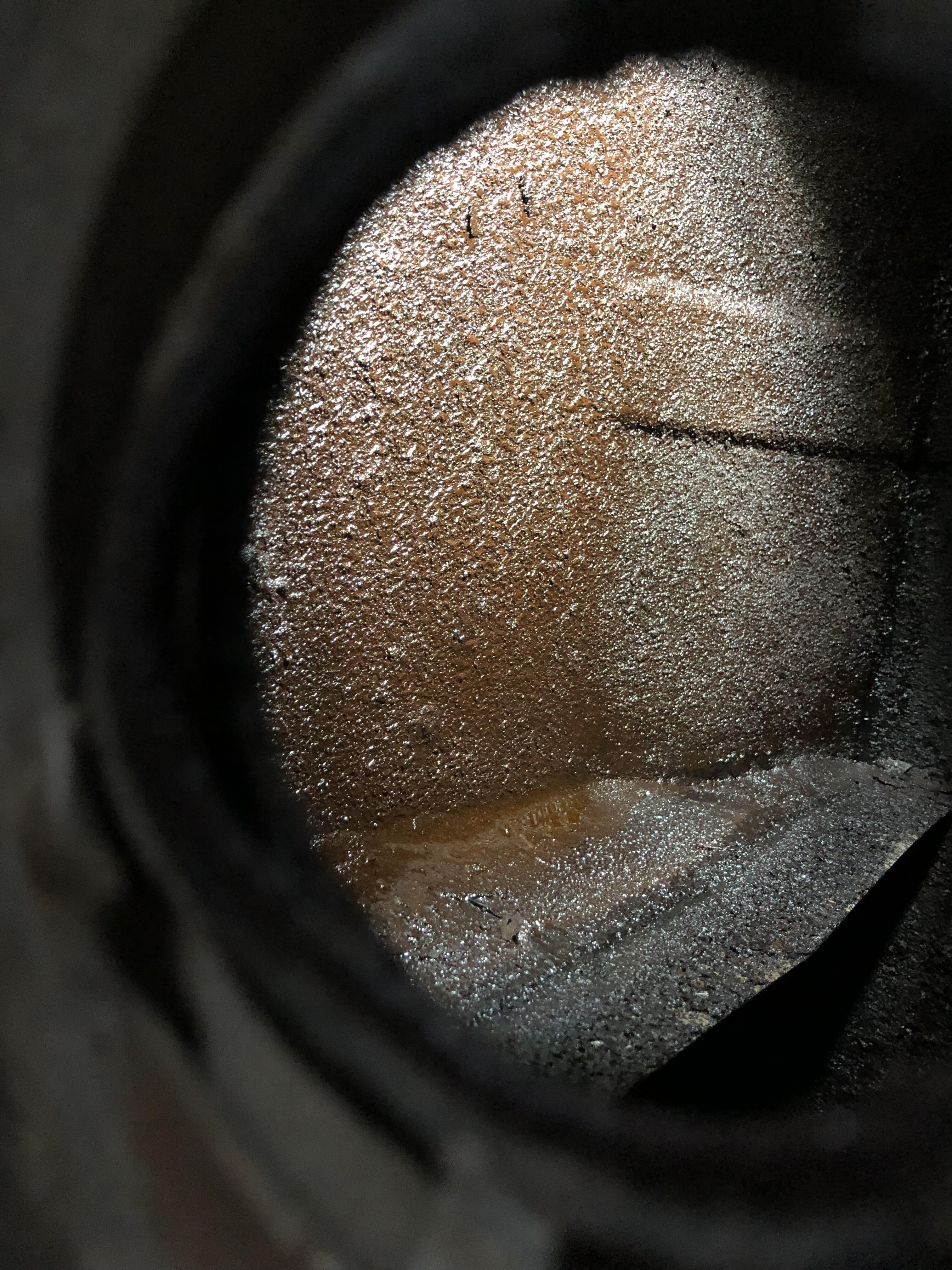
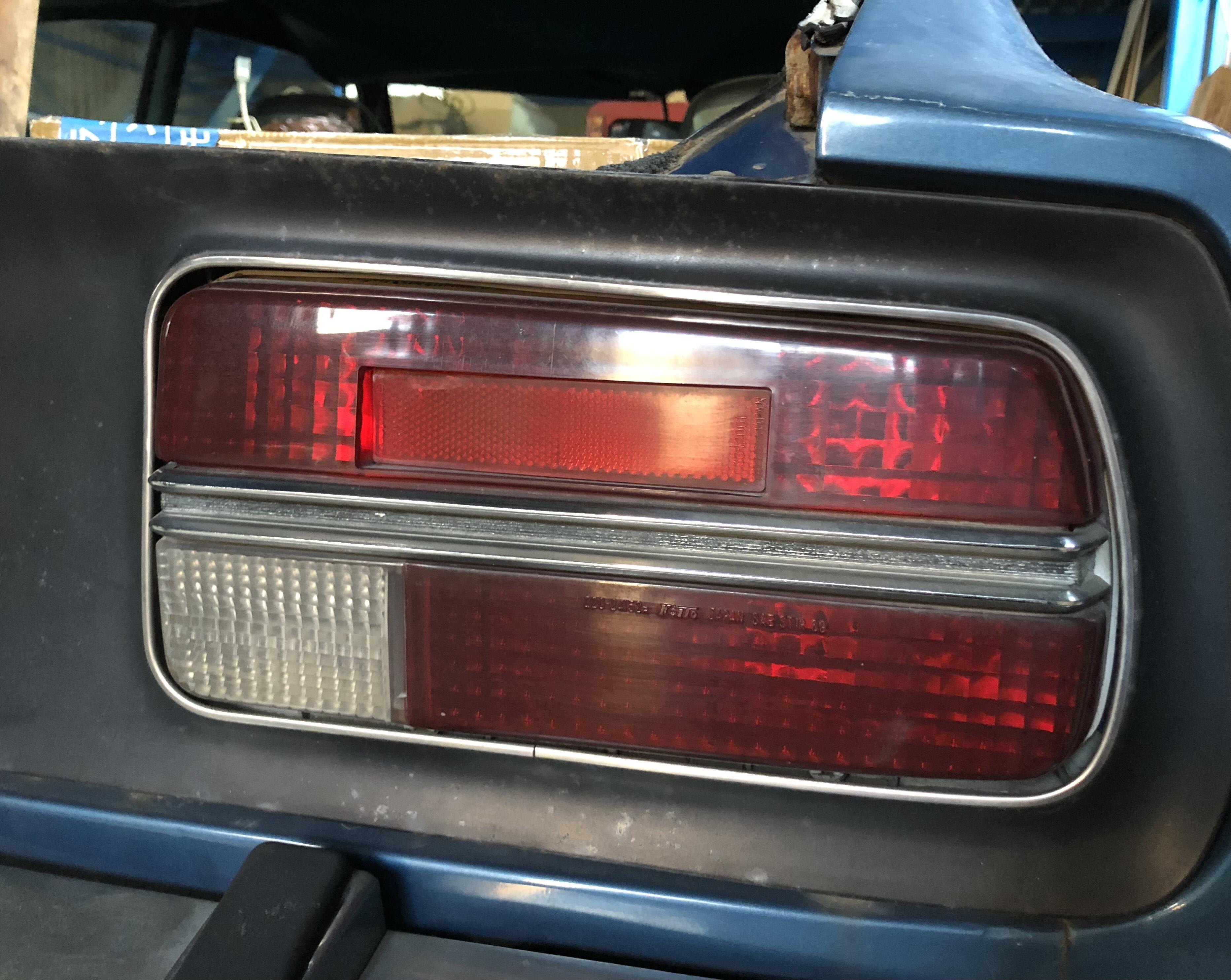
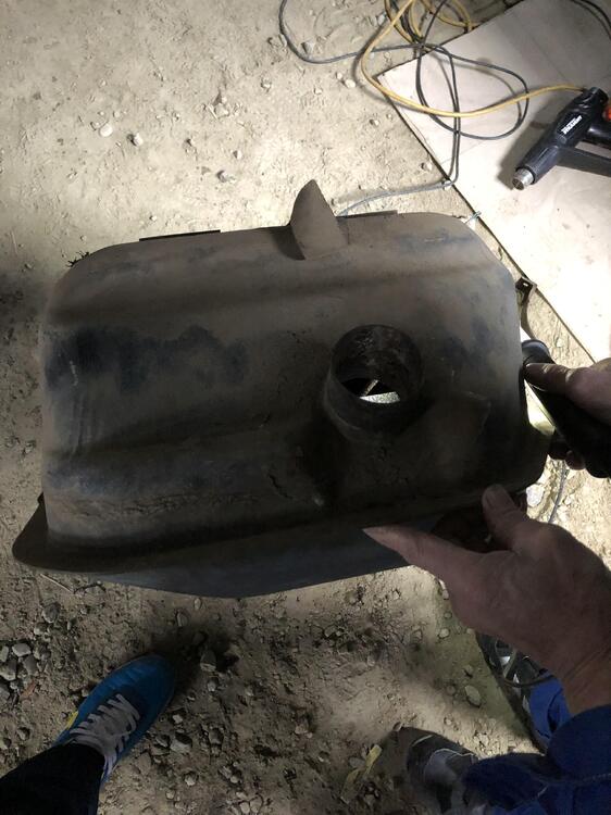
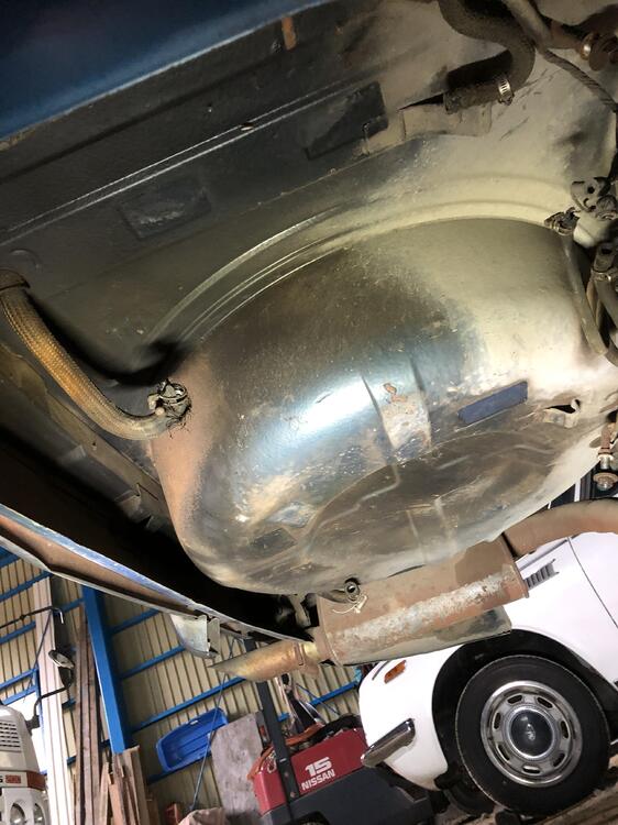
1 pointSome good and some bad , I found the both tail lights are an early one (220-24152) which don’t have markings on the lens corner like other later ones . And they can be beautiful after some cleaning. The fuel tank is full of rust , needs to be replaced or cleaned. Kats


 1 point
 -
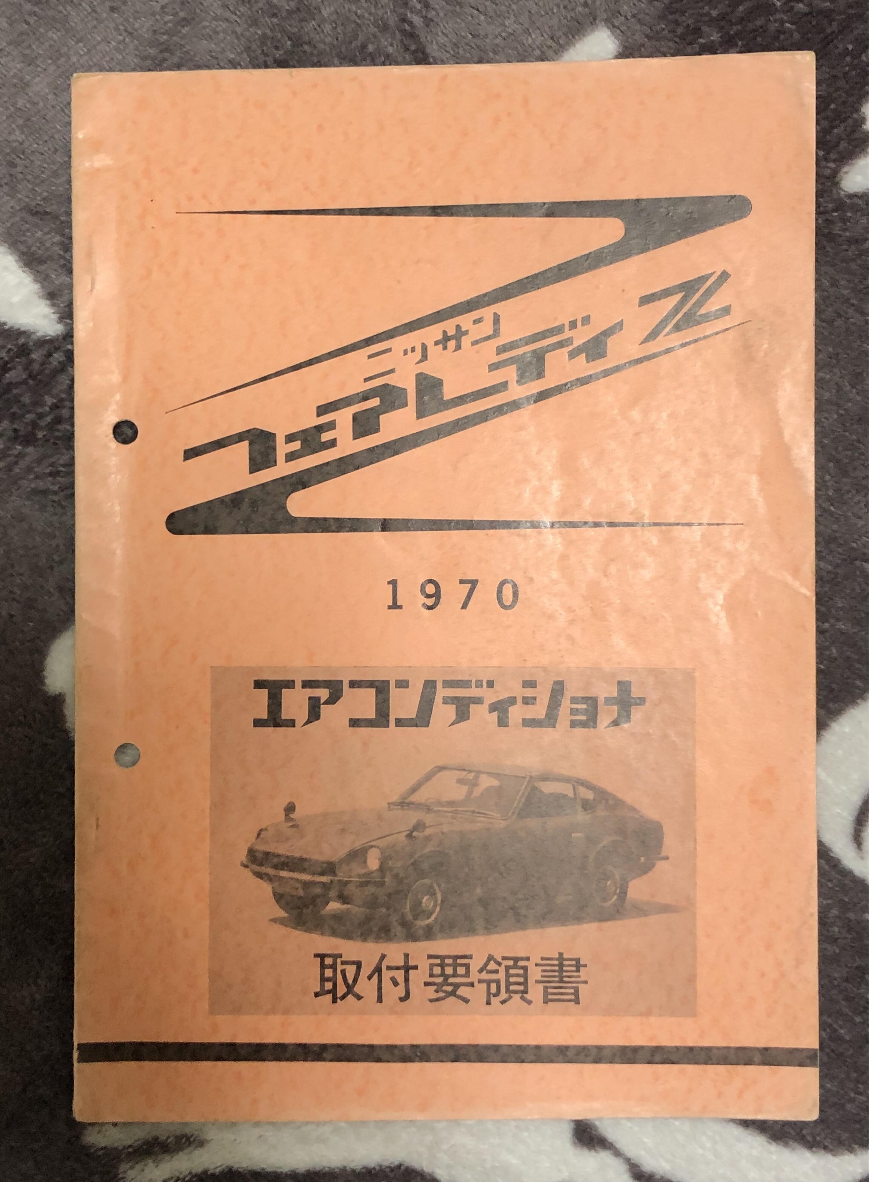
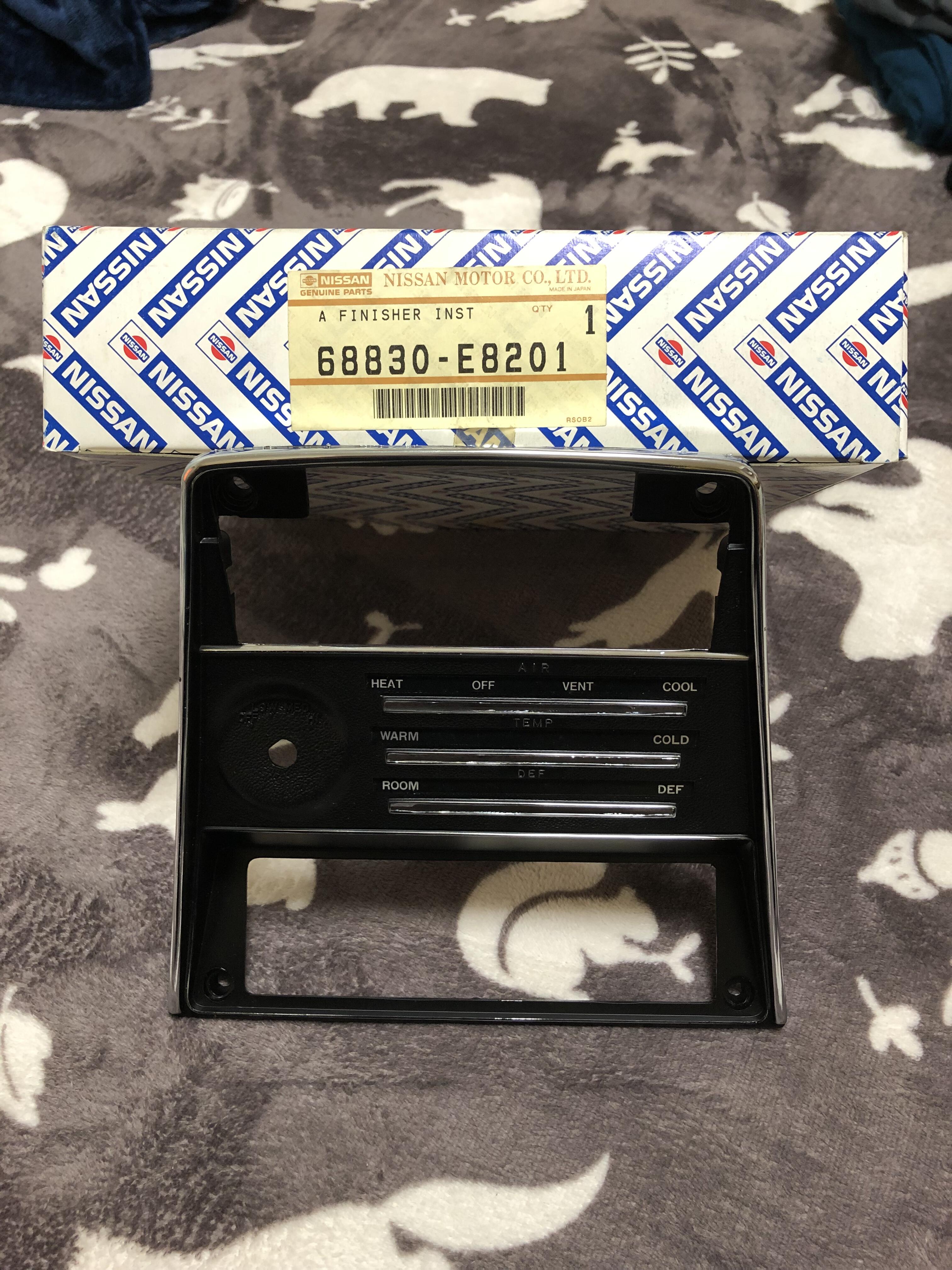
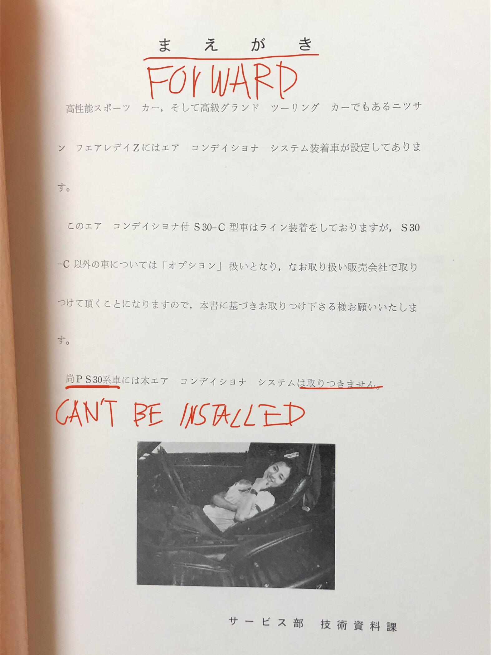
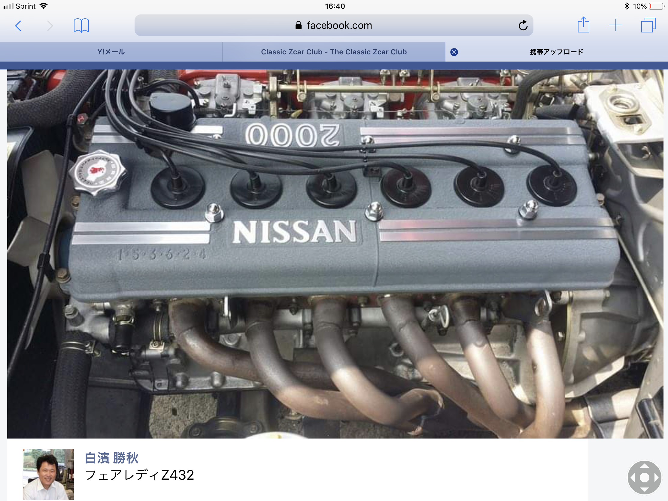
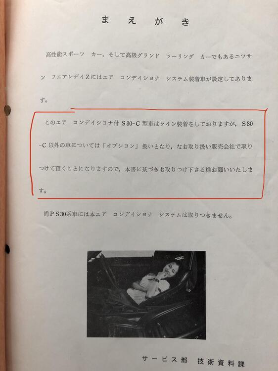
1 pointHi Mike, that is a good question, we can think the Factory A/C was available from the beginning, I mean from Oct 1969 for Fairlady Z series. Because, the very first catalog listed the A/C as an option for S30 (Fairlady-ZL ) , and the Service Shuho ( service bulletins)which Alan posted is dated at Nov 1969 . Mike , I was wondering too , the book dated July 1970 . Why ? Then I red the Forward again . It says “ the car S30-C which is designated for this A/C has been installed the system in the assembly line . However, cars other than S30-C are going to have the A/C as an option, then installation must be done at dealerships. So please refer this book for your installation “ . This leads to me a picture in my mind like this , when S30 cars were introduced A/C system was not so popular. But gradually people tended to have it for their S30 ( Fairlady ZL ) after purchased . Even some people would have wanted on their S30S ( Fairlady Z ) or PS30( Z432) which were regarded as cars they “ can’t chose A/C “ on the catalog . To accommodate those cases , Nissan issued this book making the installation easier for dealership mechanics. I think like this , what do you think of it? About S30-C , I studied a little bit . In the Service Shuho , we see Nissan gave a specific variation code for the car equipped the A/C on S30 , that is S30C ( C stands for air-Con I think) . Type code ,classification code , these are the matter of Japan Motor and transportation ministry. And those are interpreted into specific numbers and they are indicated on the registration/certification paper . A variation code is Nissan in-house code thus not shown on the paper . Having the A/C in S30 had nothing to do with Type code and classification code , so no need to declare for amendments of the paper. ( if you swapped Engine, or changed length/ width etc that is going to be a subject of the amendments ) About S30-00002 , I don’t know when the car had the A/C, I am very curious about it too . Kats
 1 point
 -
 1 pointHi Kats. Interesting that it is a rare manual. I got it on Yahoo Japan a few years ago and it wasn't very expensive. I got lucky I guess.. My 1970 Fairlady Z had an aftermarket AC system added in Japan before it was brought to the US in the mid 1970s. I wish it had the factory AC system. I'm sure that was a very rare option due to the cost. Do you think S30-00002 had the AC system when it was built? I recall a thread about that car years ago that said it had some later modifications on it when it was found. Maybe used as a test car? Was AC available as an option in Japan from the beginning of production? I believe the AC manual has a publishing date of 7/70 but I don't have it in front of me right now. -Mike Sent from my SM-G988U1 using Tapatalk1 point
 -
 I seem to remember there being a gold colored kit for the root beer colored cars.1 point
 -
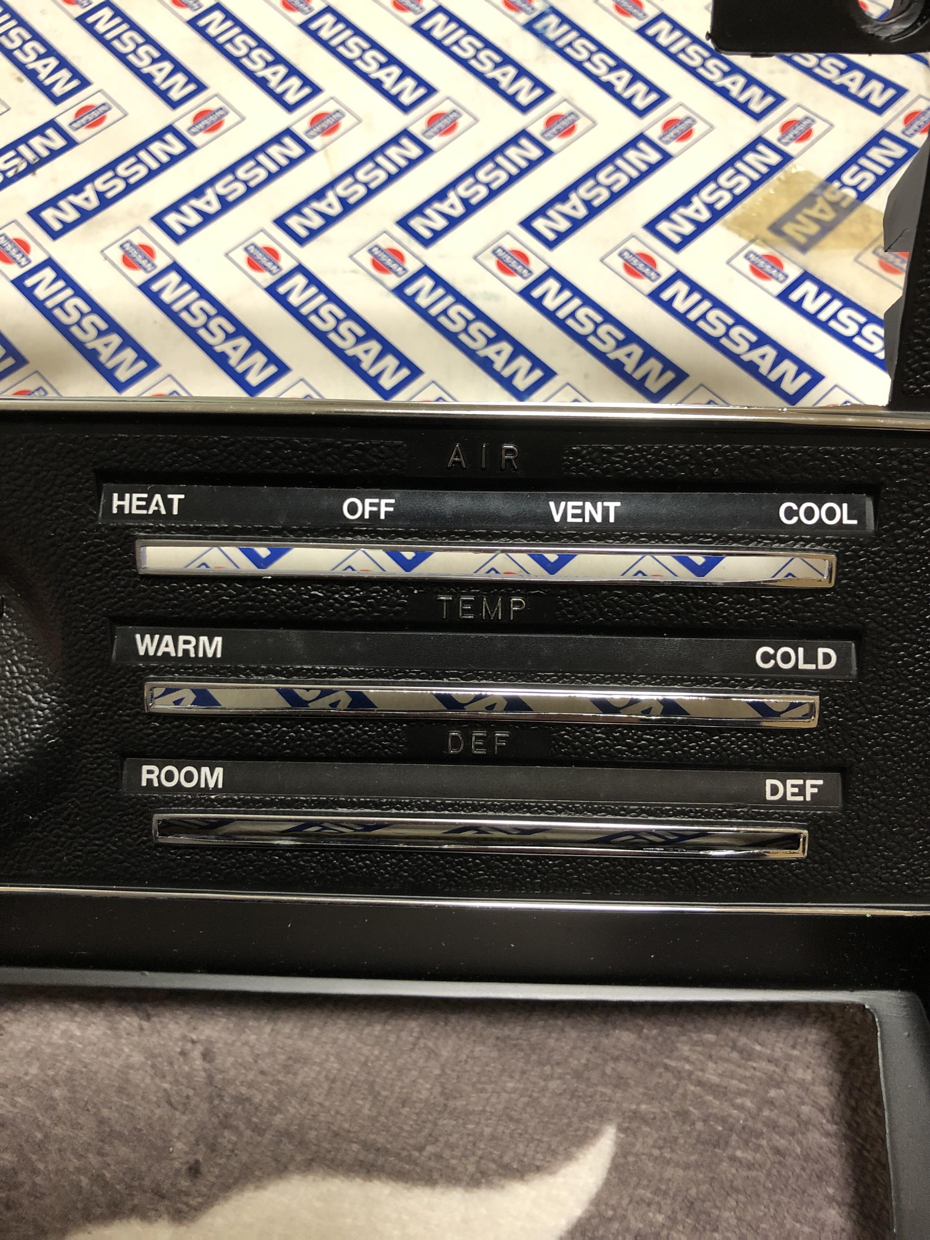
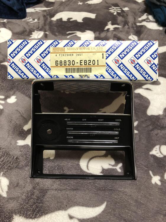
1 pointHi Mike, where did you get the book ? I am so surprised that you have this copy which might be one of the rarest things I’ve ever seen. ( I had to buy a set of six books to buy just only this copy for 100000 JPY! I sold the other five books for 60000 JPY, so crazy expensive 😰) . Anyway , we will see how wonderful Nissan factory A/C for S30 series is . And interesting to operate! First , we need this face panel to have it in our cars. Kats PS : As you mentioned above, this A/C can’t be installed on Z432 series (PS30&PS30SB) , it is described in Forward. Literally, no you can’t. But That doesn’t mean “never “ because the system was designed for L-series engined car , however piping and assorted parts under dashboard area are nothing changed. So it is possible with some hand craft works for engine Bay Area . All the things in the system can be installed as they are , except compressor mount bracket, condenser ( need to be much smaller to avoid the air cleaner box and the coolant reservoir tank ) and the FICD (it was only designed for L-series) .I don’t know why Nissan quit making A/C for Z432 , but the A/C pulley for S20 is a good souvenir for us . Kats


 1 point
 -
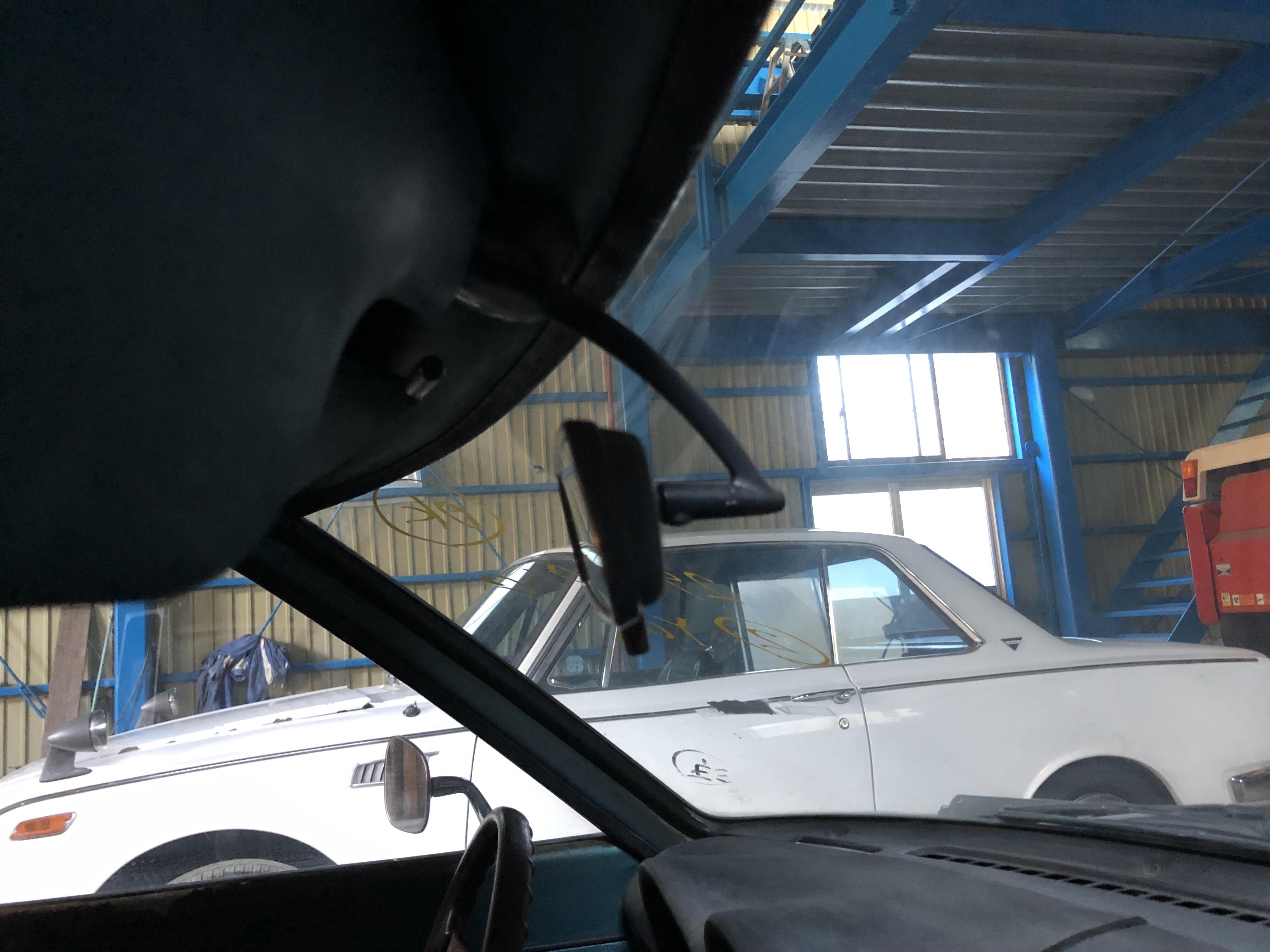
1 pointHi Gavin, we need to look at the car soon , I am surprised it was such a long time ago ! When omicron goes away , I will ask my friend to see the car in person. A few years ago he said S30-00002 was still there and covered just like the pictures. Kats1 point
-
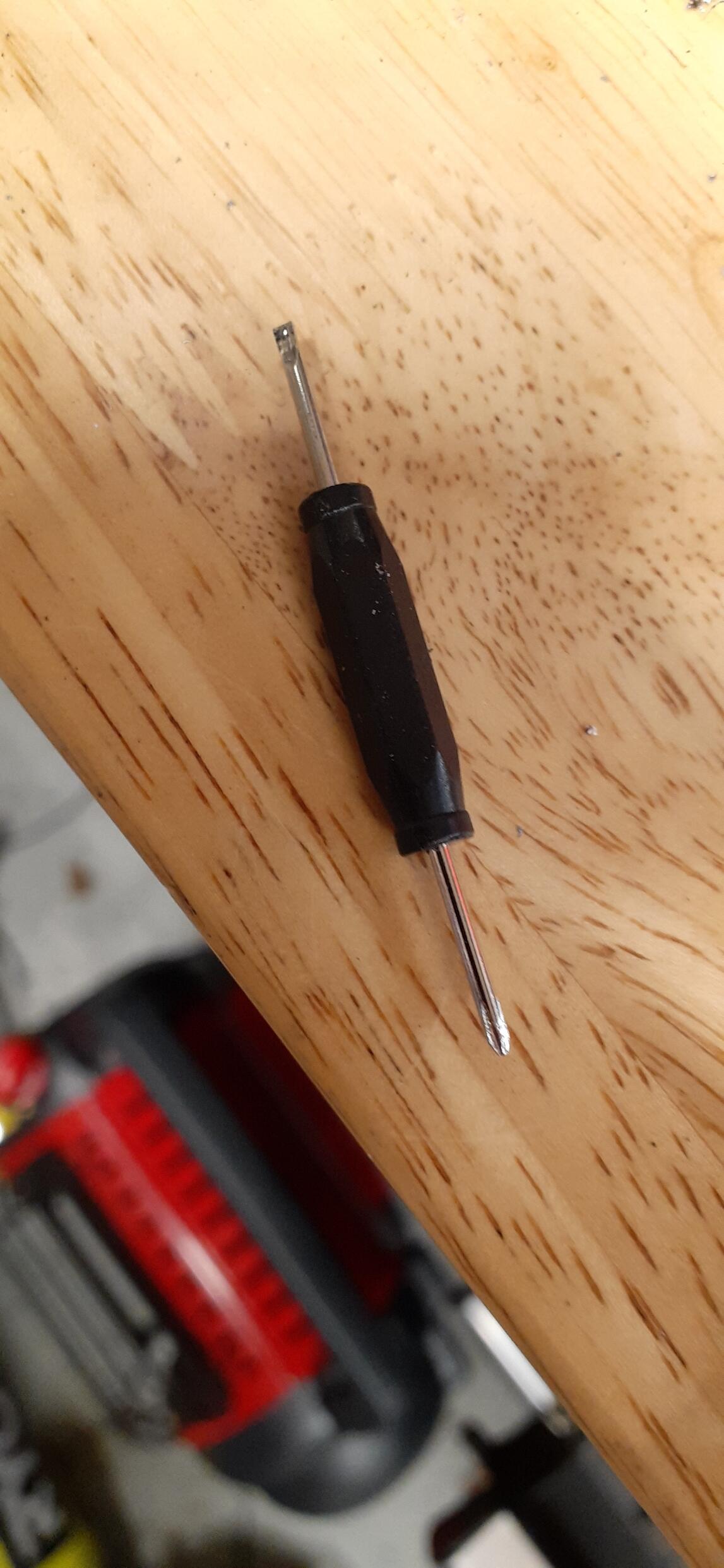
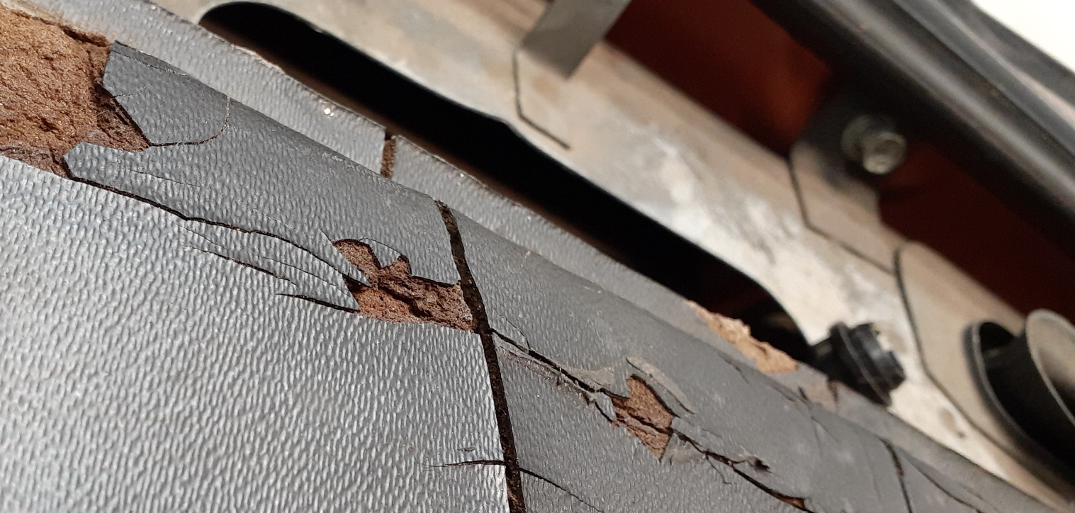
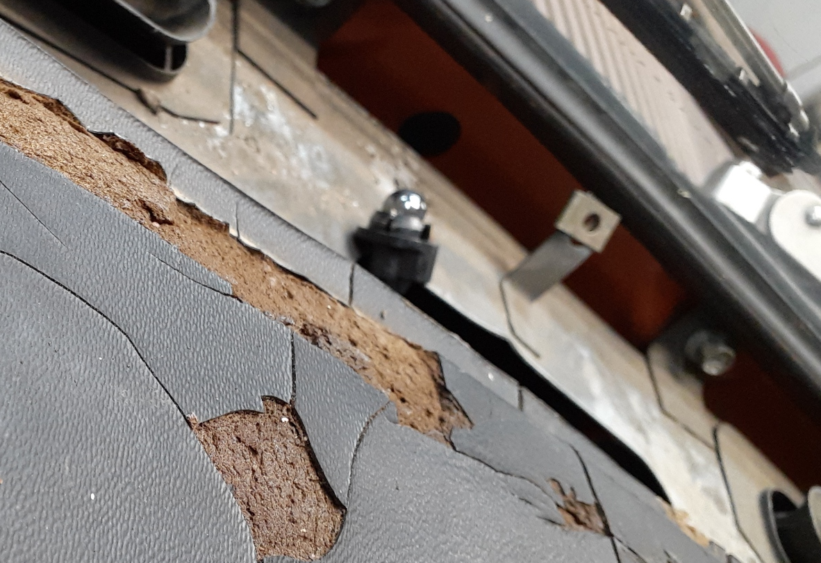
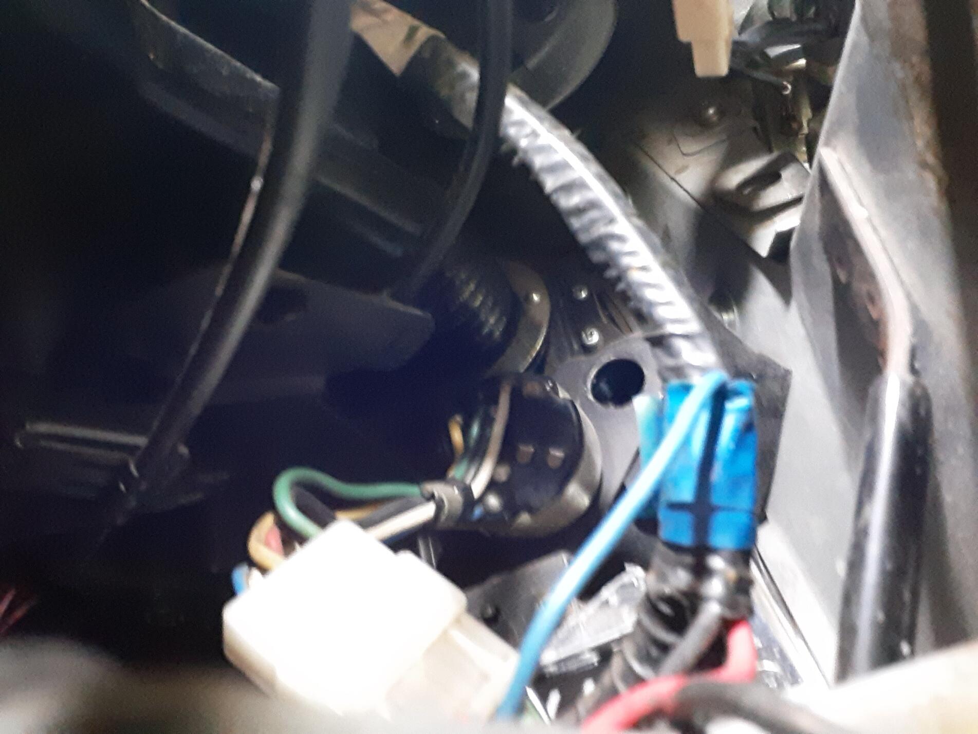
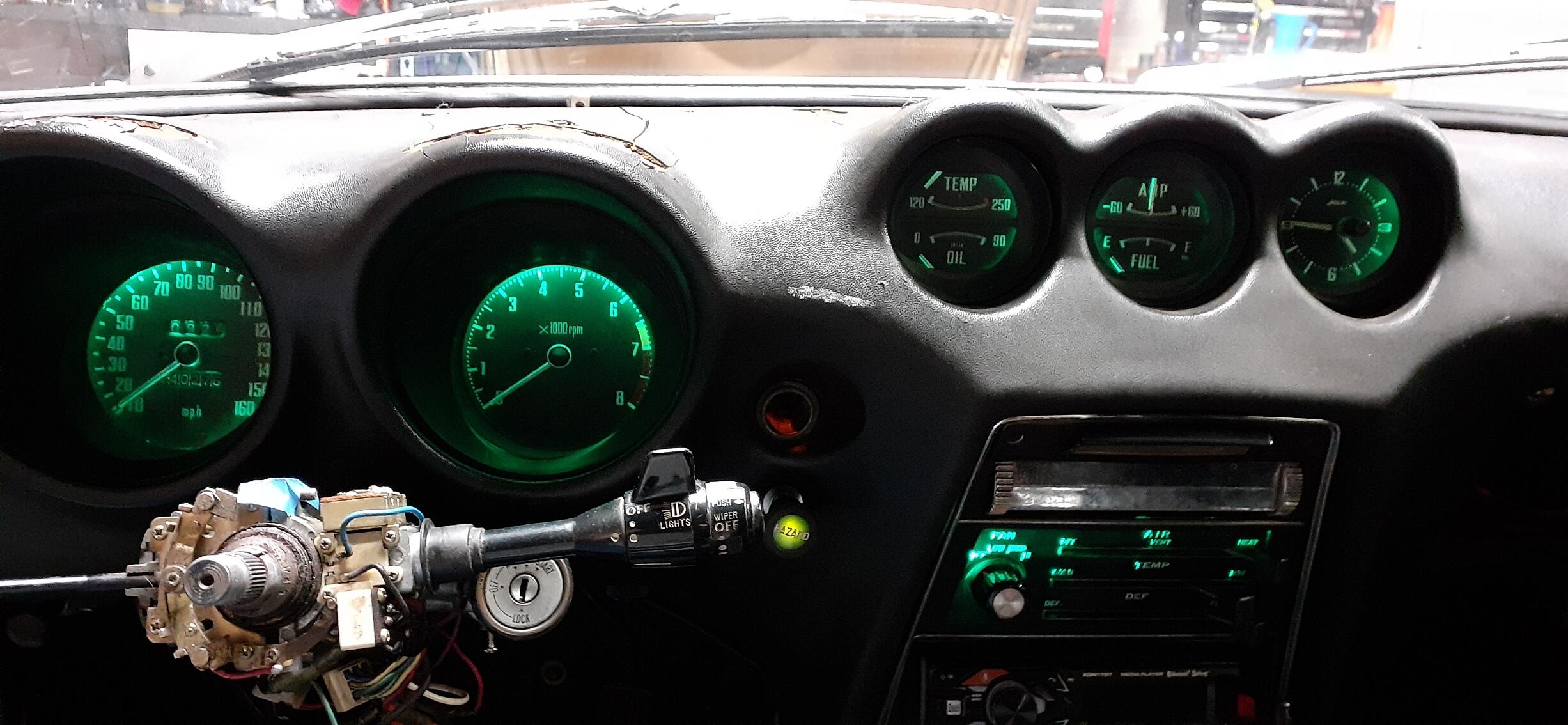
1 pointSo I got the seal for the passenger side today. I wasn't sure it would be thick enough when I did my first test fit, but I took the plunge and installed it on the full door seal. The door doesn't compress it much, and the door closes easily. I did use the top corner for the meeting of the ends. I got it just about perfect, too. Thank goodness. Anyway, the door closes easily, and it doesn't seem to rattle. I'll take it on the freeway tomorrow to see. Door Closing.mp4 I then took on the glove box and promptly wrote it off. RIP, original glove box. Well, I got the glove box door put back on for now. While I was looking around that area, I decided to go ahead and try to replace the blower motor with the Kia one I bought a few years back. After a misstep in wiring, I got the positive and negative figured out, and the fan is an improvement over the old Datsun fan. By the way, if you do that on a 240Z, use the non-latching T connector on the Kia fan. You're welcome. After that it was time to put the dash cap on. At first it wouldn't fit right. Then I remembered that I needed to remove the knob for the hazard switch, first. After that, the cap fit just right. As I fiddled with the lights, I noticed that the headlights were not coming on all of the time. There is an issue with the switch. At least I have a good stock of switches. The first switch I grabbed had a bad 9-pin connector from overheating on the parking light circuit. I replaced the connector, and I found this little screwdriver did a better job releasing the pins in the connector than the de-pinning tool. I installed the replacement headlight switch, and found the bullet on the white/red was bigger than the female bullet in the dash harness. I took it back out and found a switch that had the right sized bullet. Okay, the lights were working consistently. I put the steering wheel back on and adjusted the combo switches so the steering wheel could cancel the turn signals. I attached the horn button and got ready to put on the plate that goes on the front edge of the dash by the windshield. Then I realized I didn't put the nut back on the steering wheel. Who likes a loose nut in a Z? With the steering wheel PROPERLY secured and the horn button in place, I secured the metal plate to the dash and called it a night.
 1 point
 -
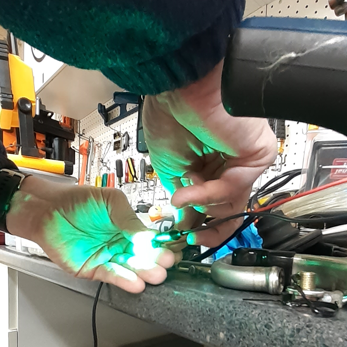
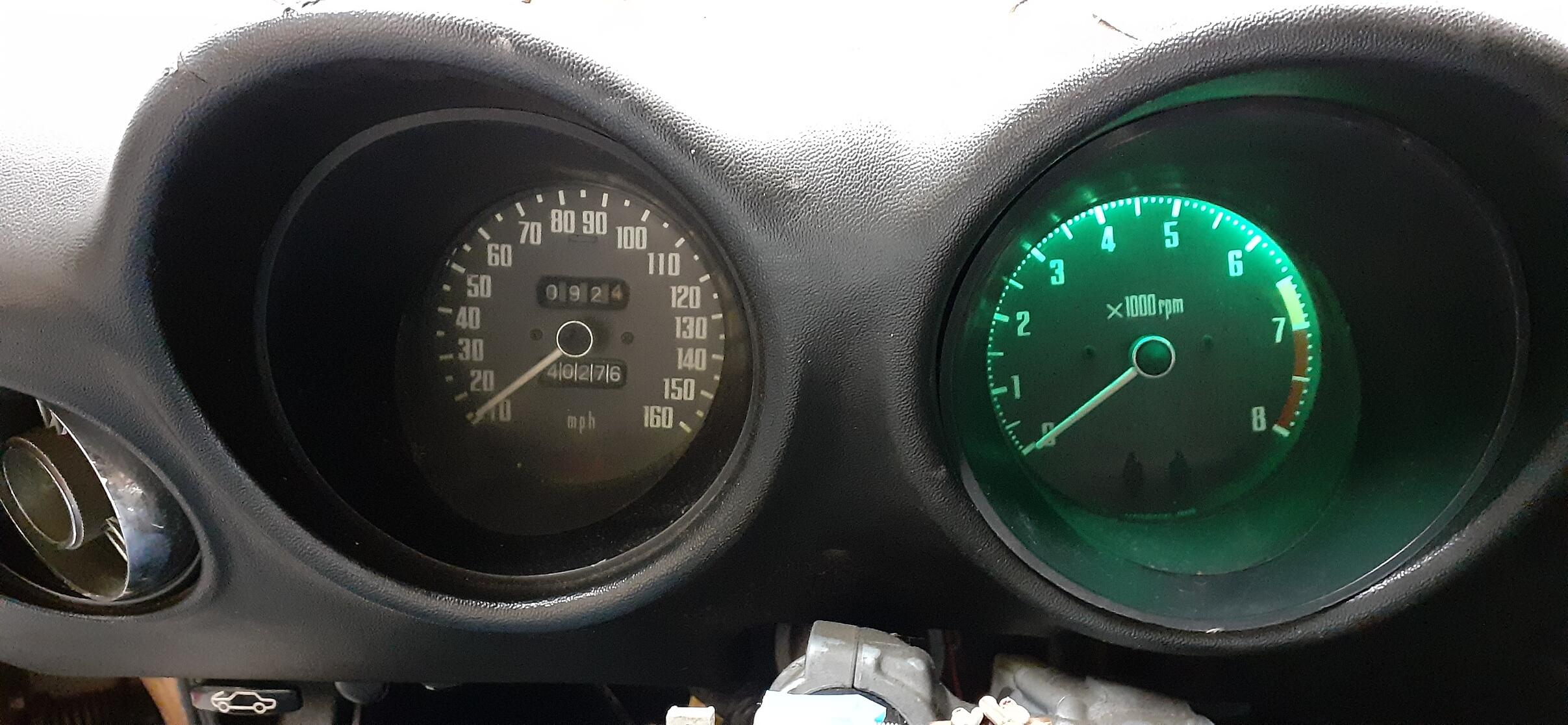
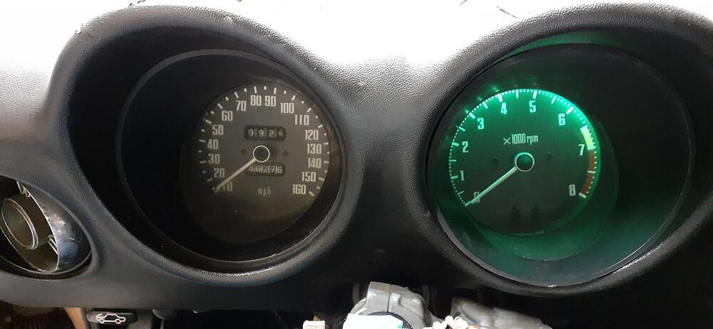
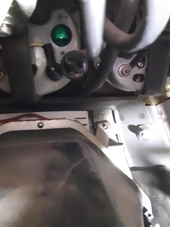
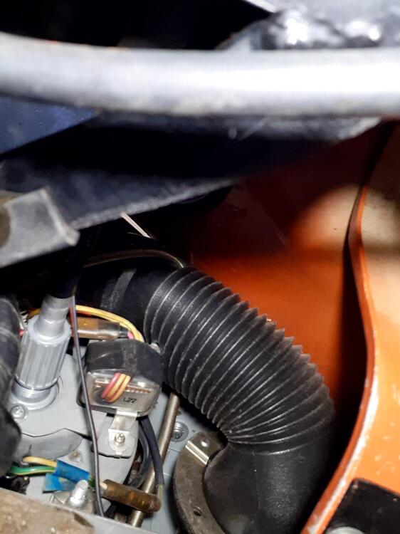
1 pointOkay, the gauge bulbs have been converted to LED. The bulbs I got today worked well. https://www.amazon.com/dp/B092VNXS6H These are green LEDs, and they are small enough that they work with the green lenses in the gauges. Prior to installing them, I ran a test with my power supply. And since the tach was handy, I did the bulbs for it and did a test lighting. So for the center gauges, I didn't want to take out the vent control panel. I manipulated the lights from the hole for the tach, from the glovebox side, and from the top. By the way a small light and a cell phone camera can go a long way to orient you to get to areas you can't see. The last photo was taken through the top of the dash with the camera in selfie mode. Far and away, the biggest challenge was the speedometer. The top bulb is a bear and a half to reach without pulling the speedometer, but I managed to get to it just with removing one wingnut and loosening the other. The bulb in question is above the module on the back of the speedometer and is partially blocked by the vent hose. Here's the wing nut that I loosened...mostly because I wasn't sure I'd be able to get it back on. And I think the results justify the effort. Pro tip on removing the old bulbs. Have a small screwdriver handy. The blade should be about 1/8 inches (3mm) wide. Press down on the bulb with one hand while leveraging the screwdriver blade against the tab on the bulb and the bulb housing. Once you get it moved away from the left, you can use the screwdriver blade to push the tab to finish rotated fully to be removed. I was pretty worn out when I was done, so re-assembly will be tomorrow, and I hope to have a new door seal arrive so it can go in, too.


 1 point