Leaderboard
-


Zed Head
Free Member4Points18,796Posts -

conedodger
Free Member3Points11,316Posts -


Racer X
Free Member3Points1,877Posts -

Randall.K12
Free Member2Points13Posts
Popular Content
Showing content with the highest reputation on 01/26/2023 in all areas
-
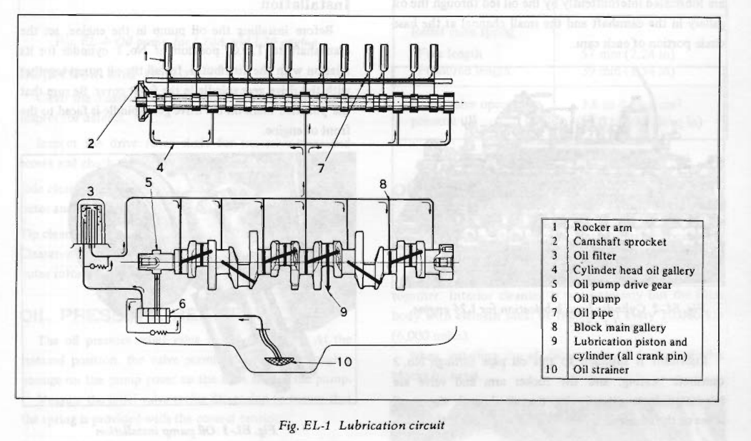
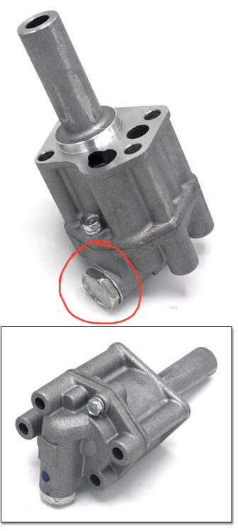
3 pointsThat is the relief I mentioned. I have worked through many different combinations of spring setups to tune the oil pump for the race engines I build. I’ve used two springs, one inside the other, single springs of varying rates, and made shims to fine tune the pressure in the system. The rule of thumb for oil pressure, in any engine, is 10 pounds for every 1,000 rpm. So at 5,000 rpm you want to see at least 50 psi, 8,000 rpm (yes, I turn these engines that fast) you need 80 psi. A couple pounds more is OK, a couple pounds less, not so much. The spring and valve are under the fitting circled in red.
 3 points
 -
1 pointCO mentioned valving. I looked around and found a mention of residual pressure valves. That could be a reason. I think that the topic has come up in past discussions, I had forgotten about it. You can hold pressure on drum brakes because there are return springs. You wouldn't want that on the front. Makes me realize that it could be a possible cause of dragging brakes, mixed-up lines. Makes you wonder though if the quality level of a reman master cylinder is really up to the level of controlling residual pressure. Another neat test bench factor to consider. Or just do F and R. "tandem master cylinder" is the search term to use. http://www.britishv8.org/Articles/Tandem-Master-Cylinders.htm "Another issue when selecting a tandem master cylinder is whether it comes with one or more internal residual pressure valves. On an OEM master cylinder designed for a car with rear drum brakes there will sometimes be a residual pressure valve in the rear brake circuit to maintain a small amount of pressure at the wheel cylinder seals. The amount of residual pressure varies from one design to another but typically is between 6 and 25psi. Disc brake calipers may or may not need a residual pressure valve depending on their design. A 2psi residual pressure valve is often recommended for aftermarket disc brake calipers."1 point
-
 1 pointI don’t know guys - I’m not going to try and figure out Nissans engineering , but the larger capacity of the piston assembly in the BMC needs to go to the front brakes . My intention now is to get Classic Tube the correct info for when folks order lines . I made them aware that the early BMC’s are not readily available and most would be going to a later BMC - which means they need different lines than what’s in the early kit .1 point
 -
 1 pointJust FYI. I had two wrong gland nuts in the package. M52 was required, but they were only M51. Without the damper centering the gland nut, it was a very loose fit and the nut popped out at around 50Nm. The outer diameter of the gland nuts should be around 51.80mm to work correctly.1 point
 -
 1 pointAny outlet restriction would not matter either*. The master cyl bore bore is the same diameter and the two circuits are in series. That means that at the master cylinder (and until downstream of the proportioning valve), It will be the same pressure in both circuits. The circuit closest to the firewall won't build pressure until the circuit towards the front of the car builds pressure (or bottoms out mechanically). In fact, neither circuit will build braking pressure until they both do (or one of the two bottoms out). Maybe there's something "safer" in having the main braking circuit (the front axle) be the one that builds pressure as the second circuit.. Or maybe there is less volume required to be moved in the drum brake circuit before the shoes contact the drum so they put that one at the front of the master cylinder? If so, it would take less pedal travel before the other circuit (front disks) builds pressure. Brake experts would know for sure. And that's not me. *Except on transient changes.1 point
 -
1 pointI looked in to cavitation a little farther and also came up with aeration. This would be caused by a leak in the suction side of the pump. The pump is above the level of the oil so you need a solid column of oil in the pickup tube to keep the pump full. If there's a leak in the tube or at the pump's suction side it will pull air in along with the oil. So, you could have an obstruction or you might have an air leak. Not sure but you might be able to rig something up at the oil pump inlet to see if the tube is pulling air along with the oil. I don't have a mental image of what would be involved there. Pretty interesting stuff. https://www.machinerylubrication.com/Read/30768/cavitation-or-aeration https://www.machinerylubrication.com/Read/28767/gear-pump-cavitation1 point
-
1 pointMight help to have an illustration of the oil path to ponder. Pressure is caused by resistance to flow. Flow starts at the oil pump. You said that you installed a new oil pump, but who knows about its quality. The oil pump has a relief valve that could reduce pressure. The oil filter area has a relief valve but flow will still be resisted by the main bearings and the restrictor at the supply to the head. So that bypass doesn't really matter. Hard to know how much oil could pass through that restrictor to the spray bar. I think that I saw it in one of your pictures. And, apparently, some engines have another supply passage to the head at the front. It's not shown in the illustration but I have a vague memory of reading about it. A thought that just occured - the fact that pressure reduces at higher RPM might be caused by cavitation. Which could be caused by a restriction in the supply to the pump. So, it kind of circles back around to the pickup tube. Maybe you got a gasket on backward or something. The pump just moves volume. Pressure is caused by restriction.
 1 point
 -
1 pointActually, the hydraulics of the system mean that both ends get the same volume for the same amount of stroke. Might just be that the F and the R are there so that the mechanic knows where to put the reservoir.1 point
-
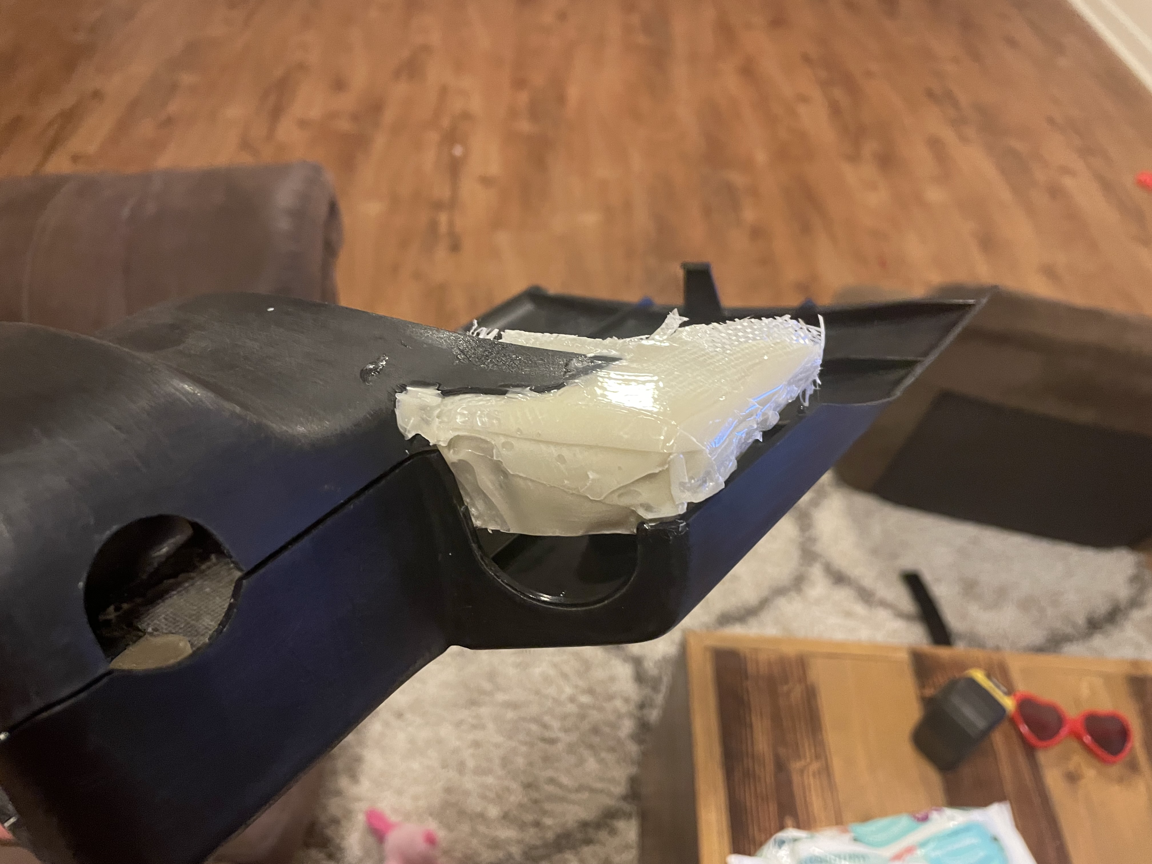
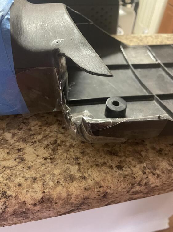
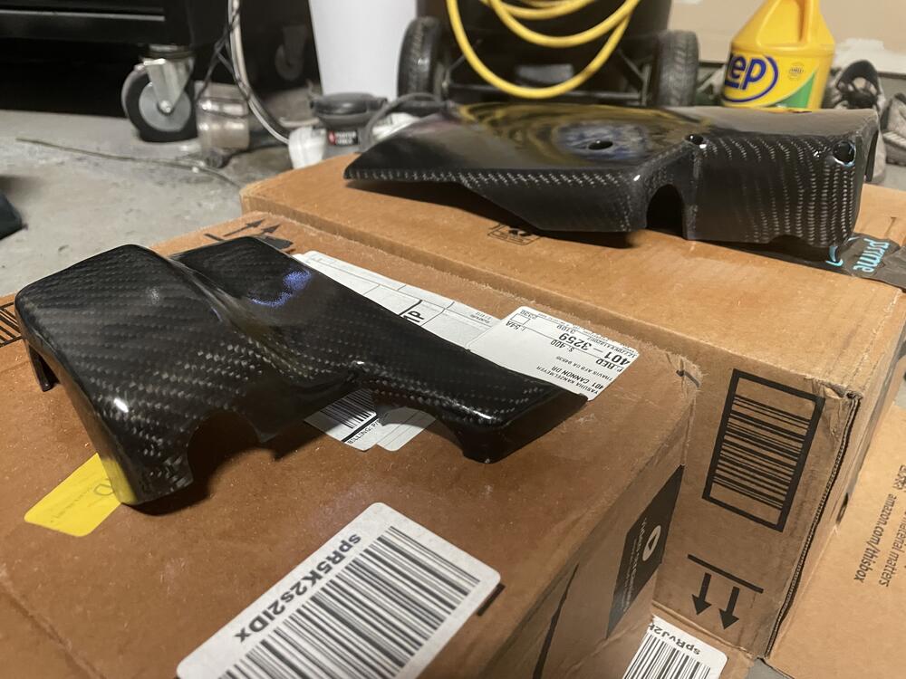
Thank you for this post. Swapped the screen for fiberglass cloth and treated it more like a layup, but I used this epoxy to bond everything. I'm happy with the results I'm getting.1 point
-
I've been doing some work on my plastics lately. JBWeld Plastic bonder epoxy bonds to the plastic nicely. I'm using a combo of that epoxy and fiberglass cloth rebuild voids and to give breaks and cracks a little extra reinforcement. It's super messy, but it's also strong and I expect additional longevity out of the parts. With this solution, you could work on the back side of the part for minimal refinishing.

 1 point
 -
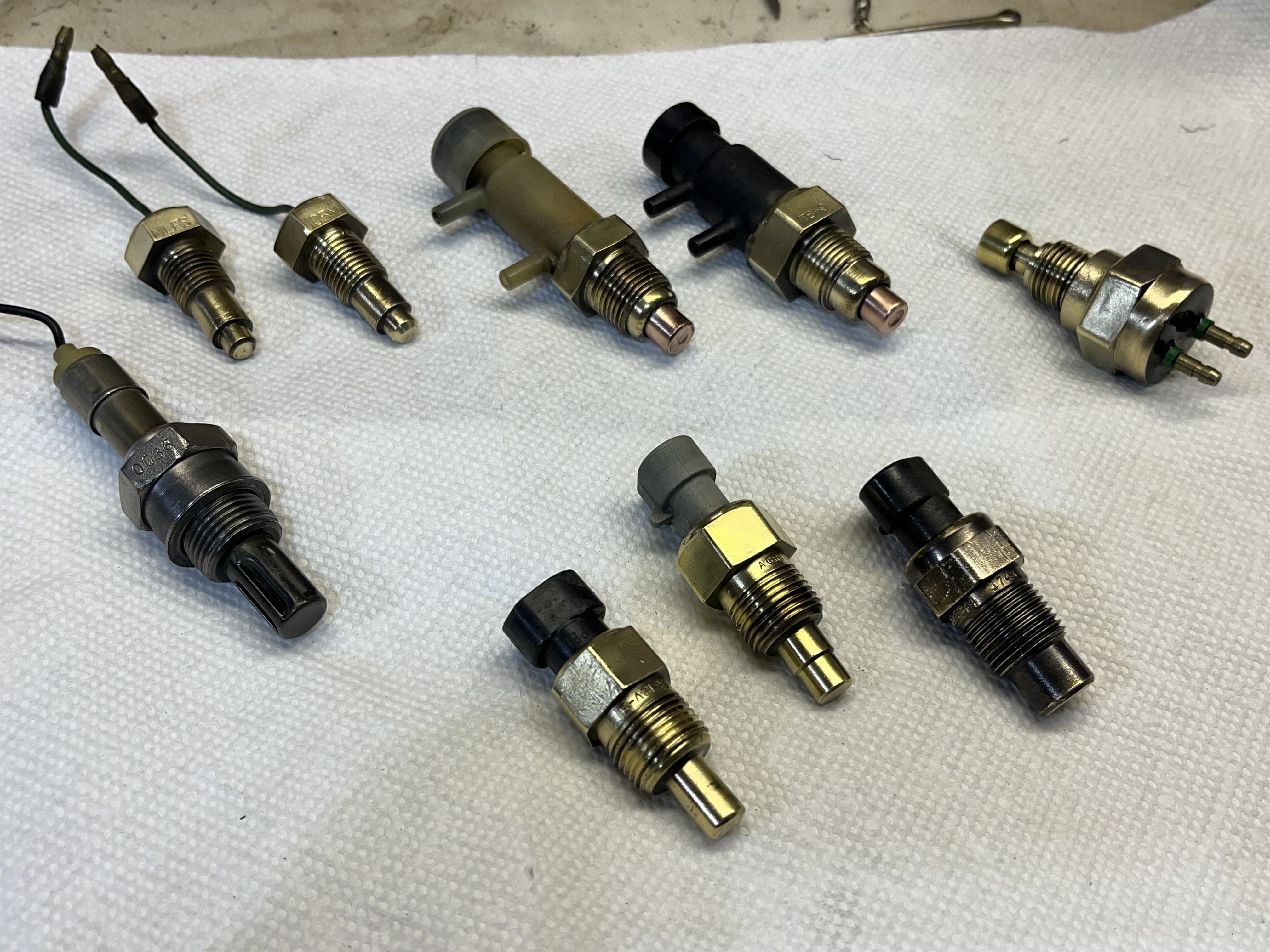
 Thanks for the tip...I guess you could call it a hoard...but I'm trying my best to thin it out. I collected a lot of Z parts over the years from guys who were sending their Z's to the scrapyard...no harm in having spares I figured...but after those parts just sat in boxes in my garage for decades I finally came to the realization that I would prolly never use them...so it's time to find new life for them...the sensors cleaned up nicely with a little wire wheel work!
 1 point