Leaderboard
-
KenFirch
 Subscriber
 8Points271Posts
 -
Patcon
Subscriber3Points11,122Posts -

Jeff Berk
Free Member2Points619Posts -
HusseinHolland
Free Member2Points1,031Posts


Popular Content
Showing content with the highest reputation on 06/07/2024 in all areas
-
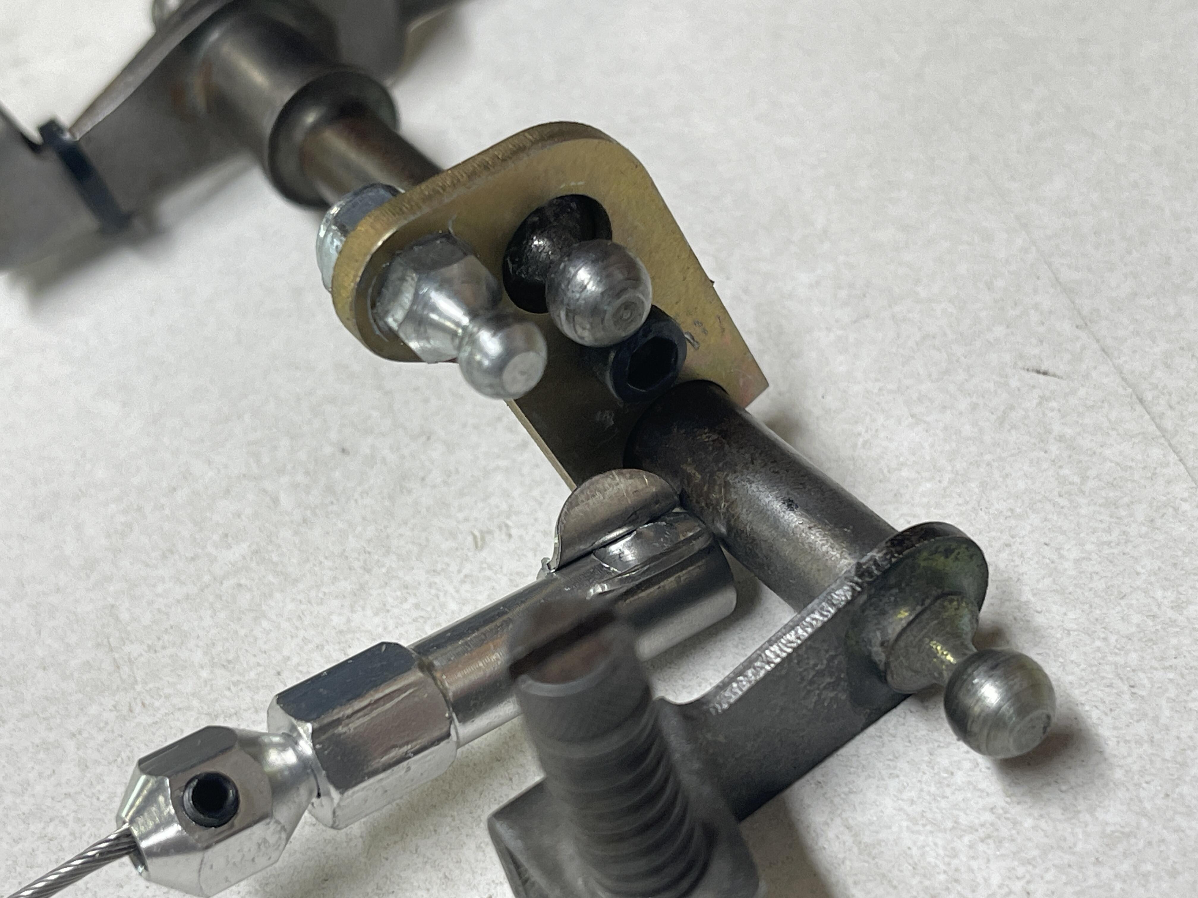
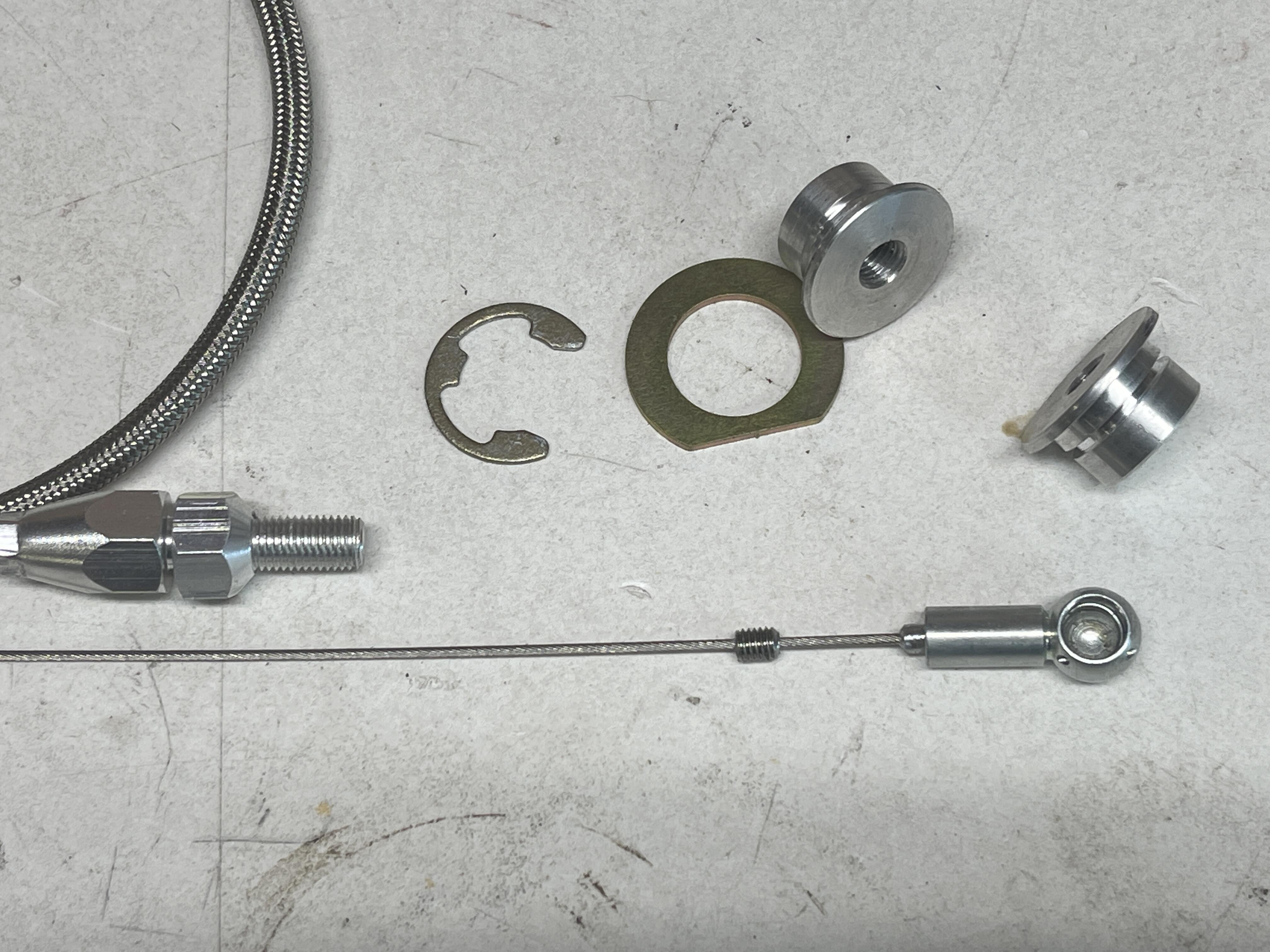
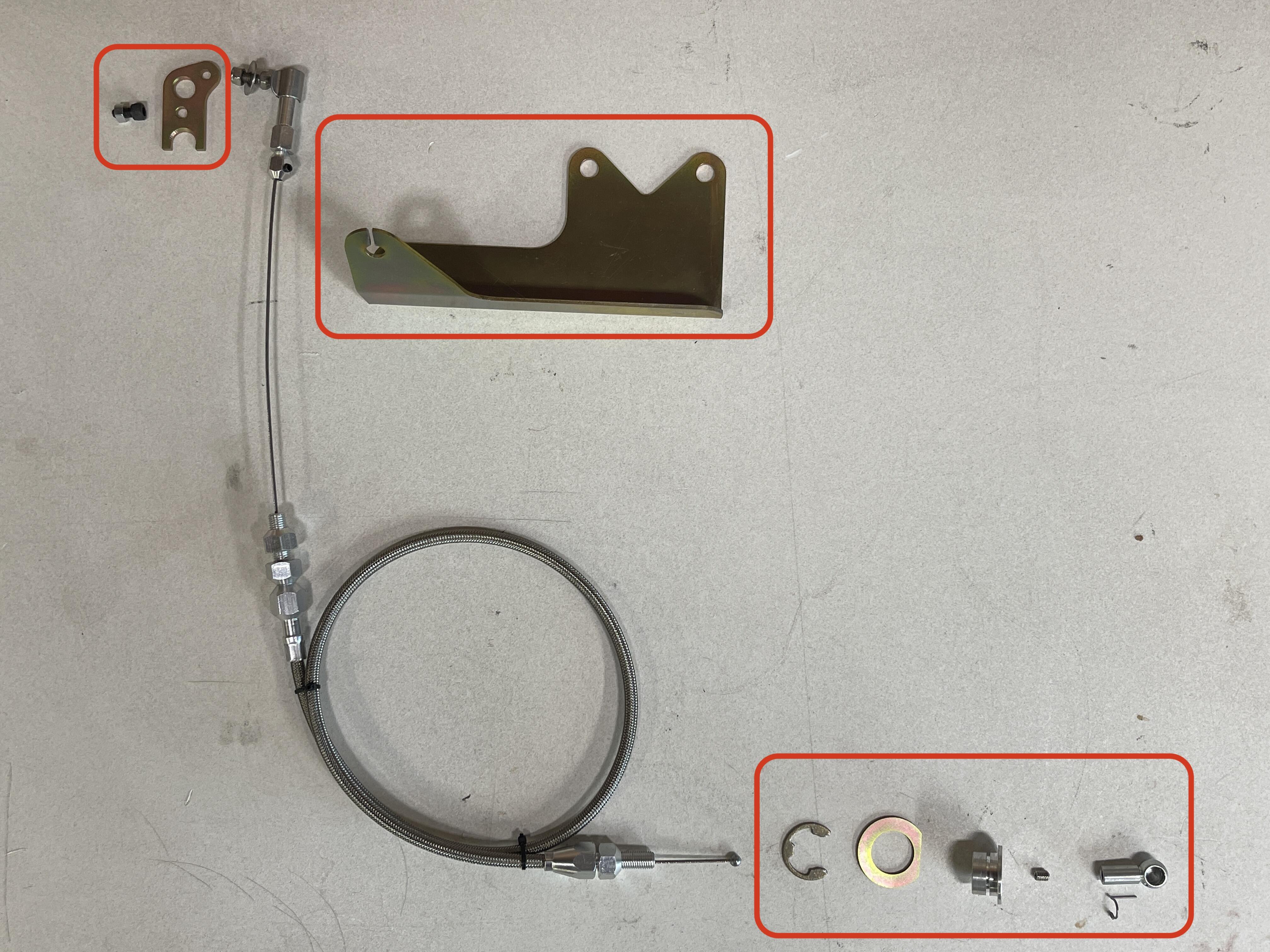
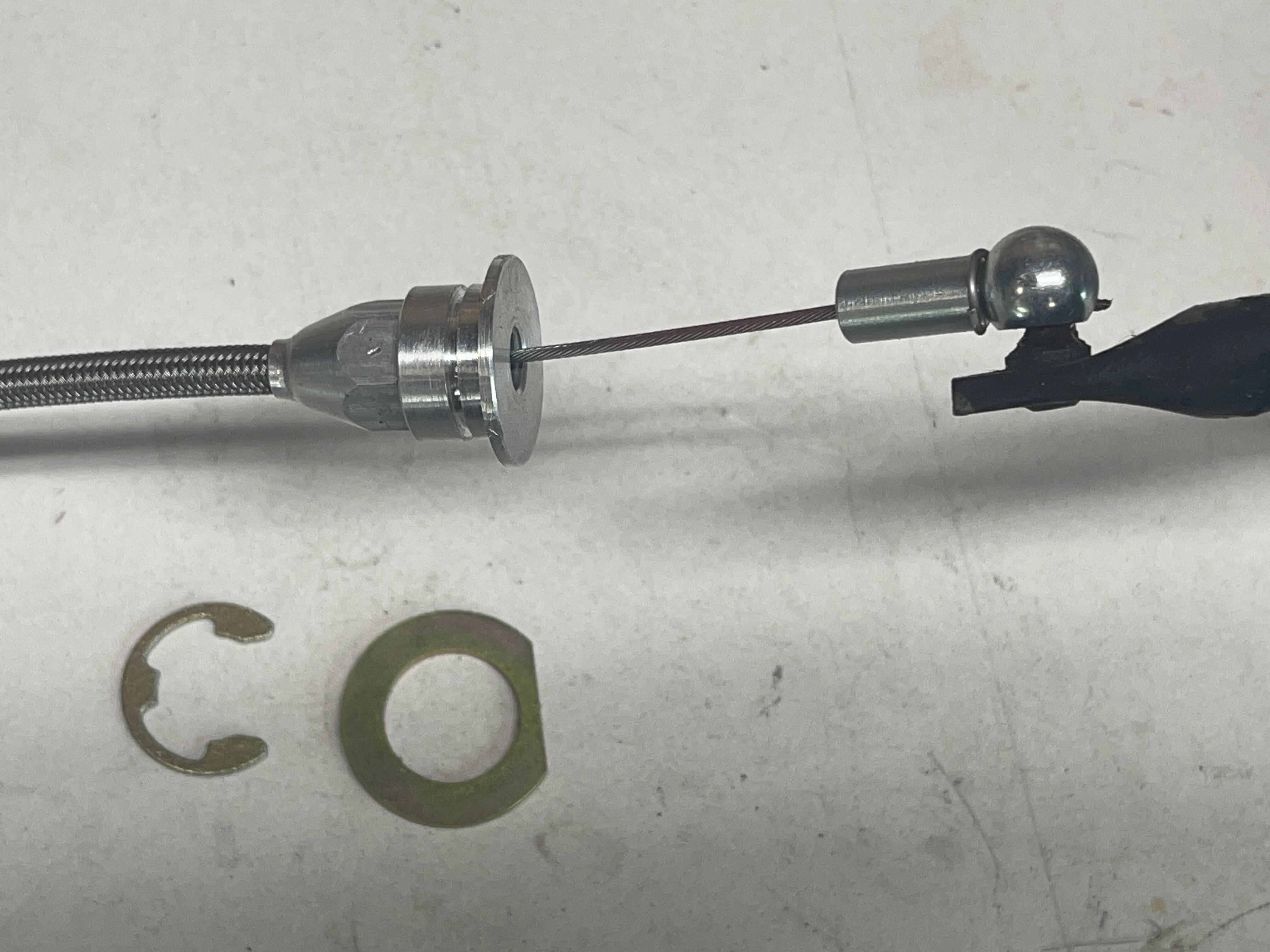
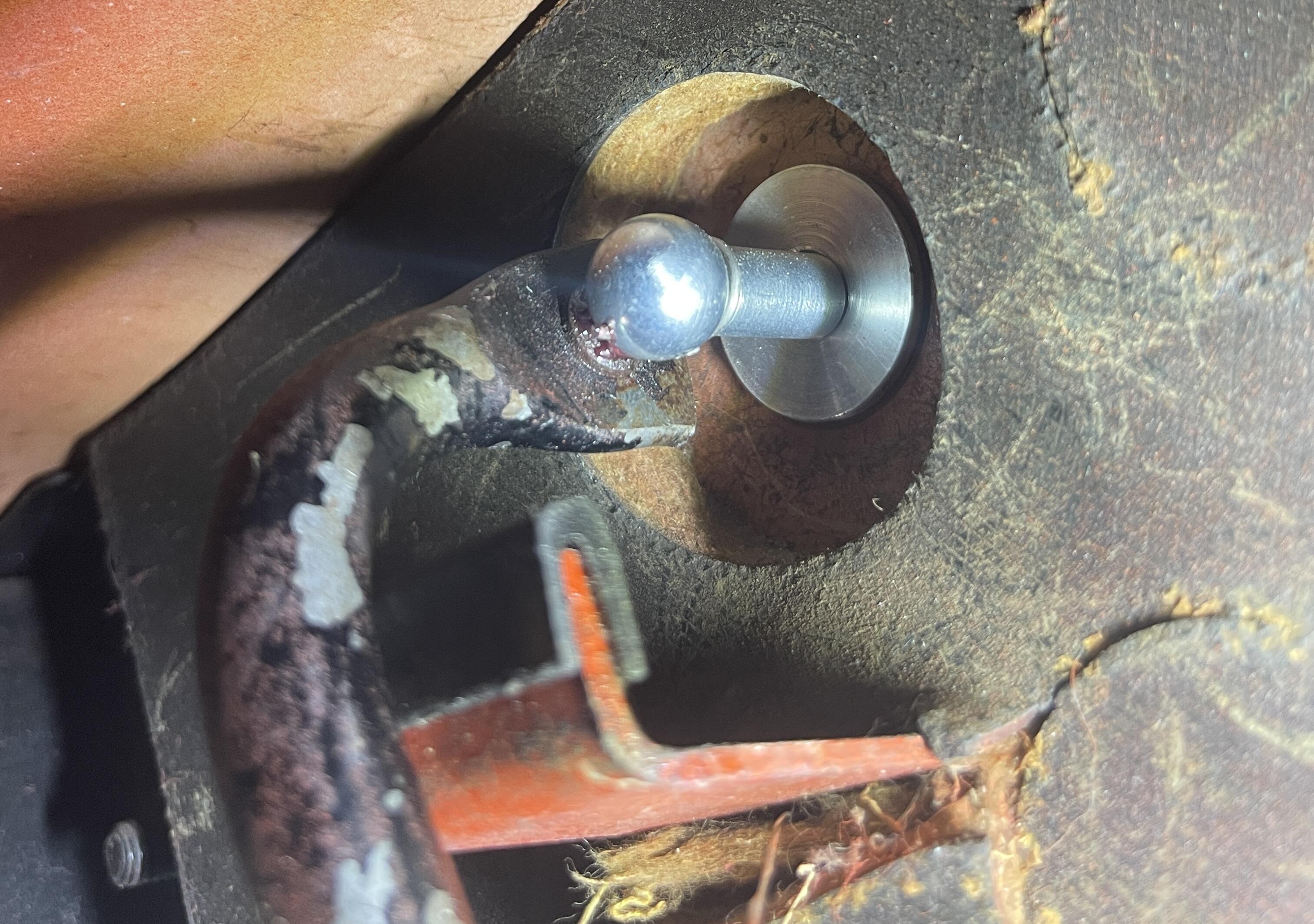
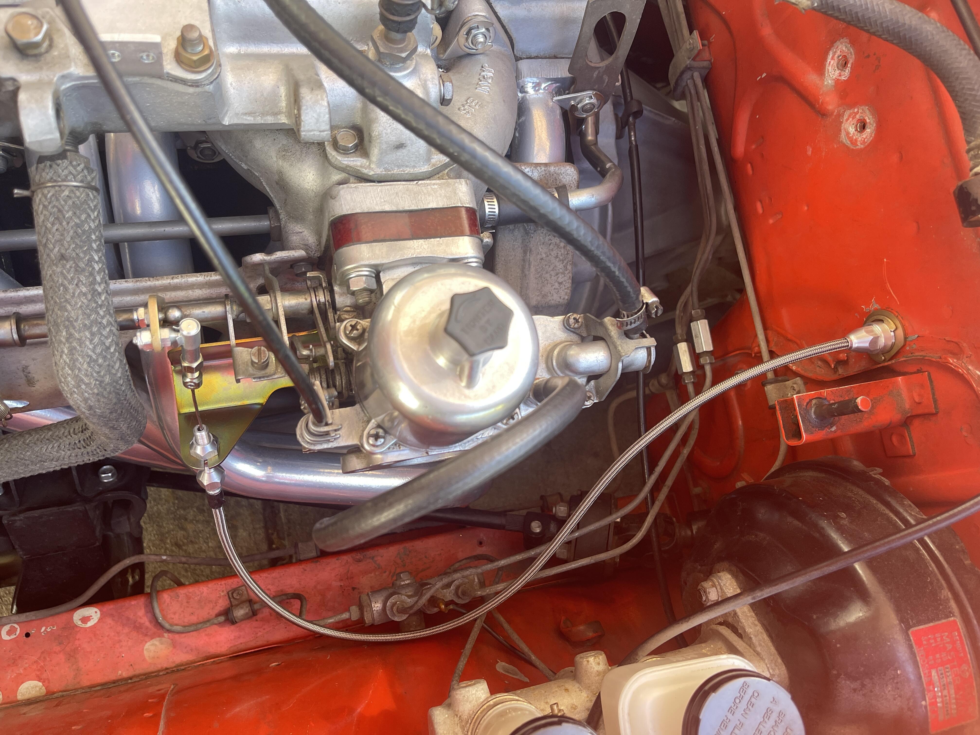
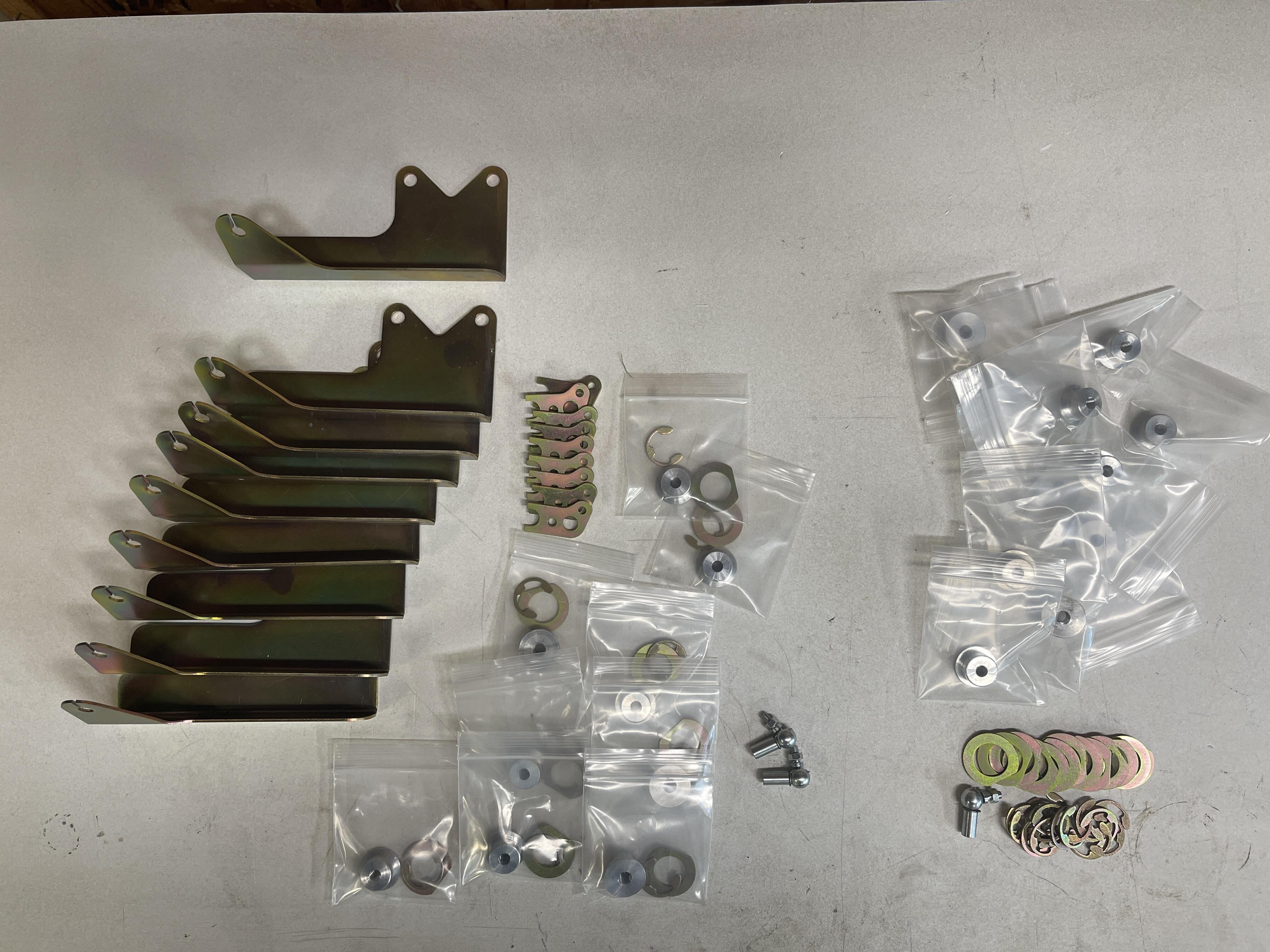
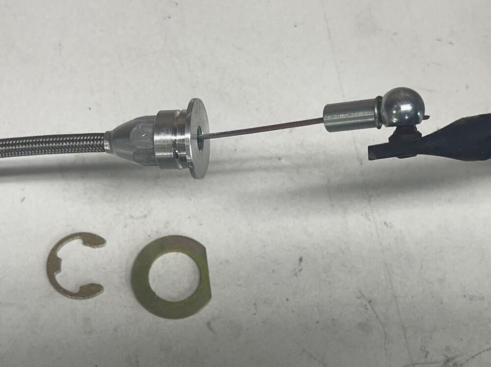
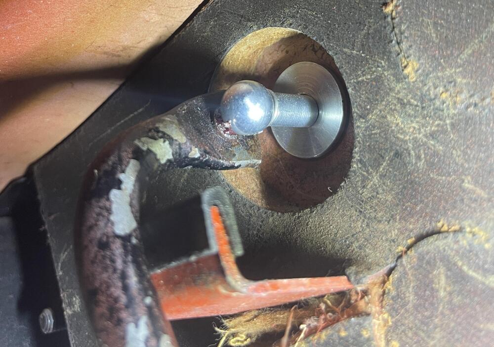
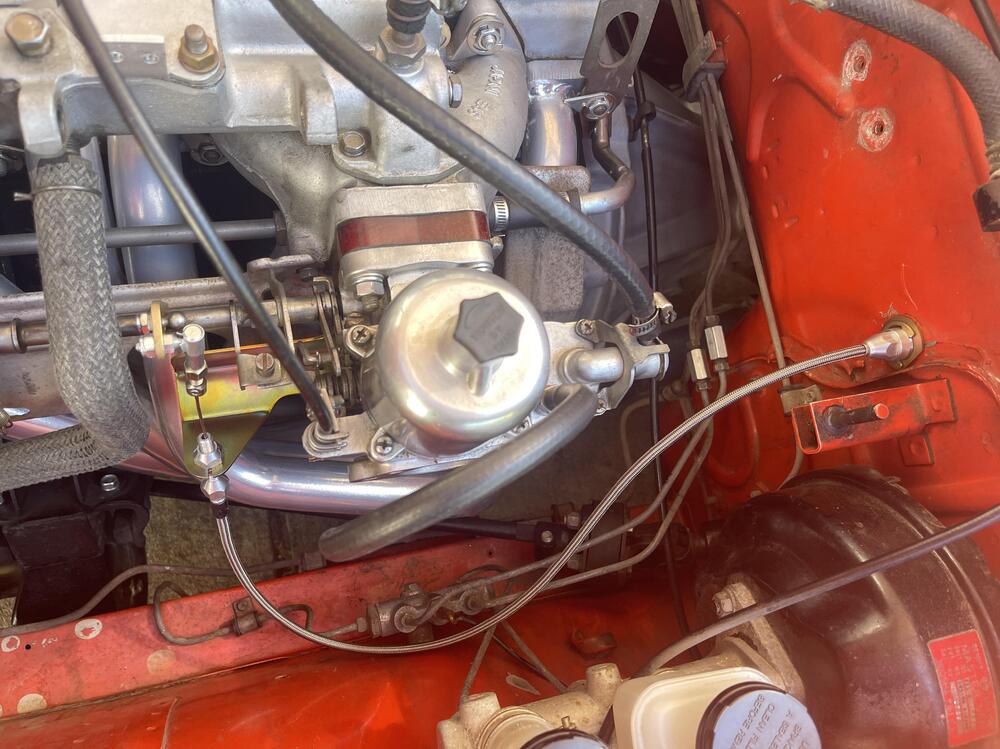
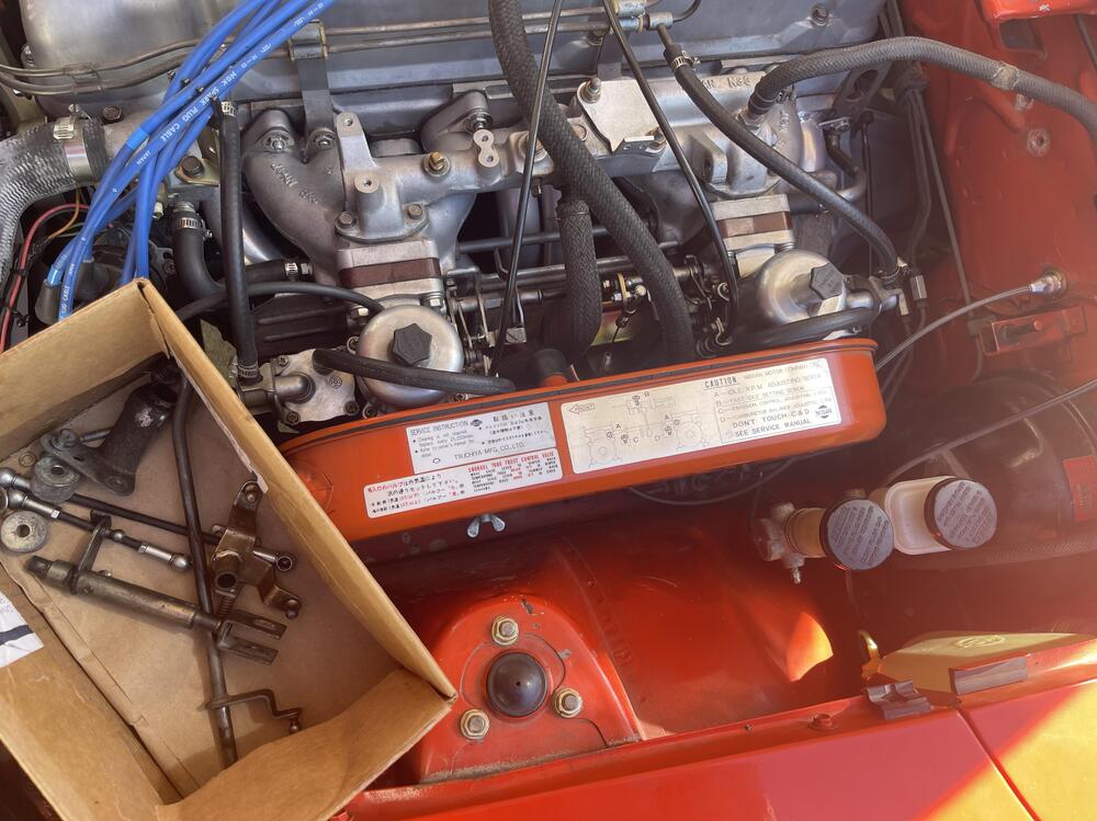
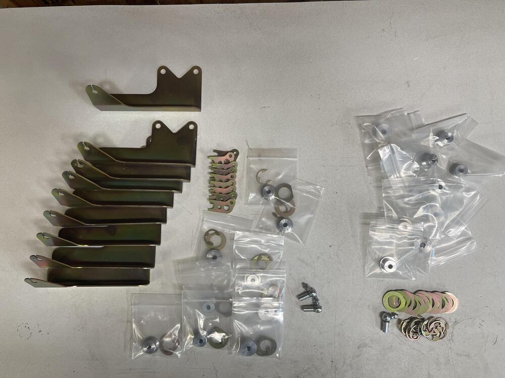
4 pointsI've been looking for a good throttle cable kit for my 73 240Z with SU's, but couldn't find any. I heard MSA had one, but no luck finding any links or info. There's an ArizonaZCar instructions link I kept seeing, but link is broken. So, seeing nothing available, I decided to build my own. Actually, I put together a few kits (9 more left) thinking maybe others might also be interested. You provide the cable kit, but you decide if you want to spend more for a Lokar cable, or a cheaper $20 Amazon knockoff. The design objectives were: Use of readily available 24" universal throttle cable kit (you provide). No junkyard rummaging needed. No welding or modification to gas pedal. Stock ball is used. No drilling of firewall. Completely reversible if you want to return to stock setup. Only 1 hole needs to be drilled in the carb linkage. Cable runs from carb linkage all the way to gas pedal so you can completely remove old linkage. High quality parts. Plasma cut, yellow zinc plating, and CNC machined bushing. Circled parts are included. You provide the 24" Lokar TC-1000HT (braided), Lokar TC-1000U (black), or a cheaper knockoff. The Lokar is better, but any will work, as long as the adjuster threads are 5/16-24. Just so you get a taste of the install process, here are abbreviated instructions. I'm working on a more detailed set for purchasers. Remove the 4 nuts from the rear SU carb, slide away from engine and remove center linkage. Slide carb back on studs to hold, you don't need to remove any cables or hoses from the SU. The only modification needed is drilling a 3/16" hole in the stock lever so a new lever can be bolted in place. New ball is placed further away from linkage centerline to help give better off idle control of rpm's. Reinstall center linkage and place bracket onto the 2 lower studs of the SU and tighten carb back into place. At this point you could reinstall your old linkage if want to finish project later, or test to make sure your SU's are still happy. Slot provided so you can pull cable away from engine without loosening the cable set screw. On the firewall/gas pedal side, remove gas pedal by removing the 3 screws. You'll need to make the ball end of the cable smaller in diameter so it will fit inside the socket's M5 thread. I twirled mine on the side of a grinding wheel, but a file could work. Then run the Allen head set screw (it has a hole drilled through it) onto cable and into socket to lock cable in place. Red thread locker or small center punch on threads to lock set screw in place if needed (after checking fit at gas pedal). Discard the adjusting nut and replace with firewall bushing after cutting the threads to about 3/8" in length so they don't stick out of the firewall bushing. Tighten cable sheath to firewall bushing, large diameter side facing to rear. Slide cable back into sheath and attach socket to your gas pedal linkage ball. Feed cable through firewall throttle hole until bushing is against inside of hole. I found it easier to feed cable through sheath now, leaning gas pedal against trans tunnel, instead of trying to feed that small wire through that tiny hole afterwards. I hate working under dashes and definitely didn't want to have a nut to tighten above the gas pedal. From engine bay side of cable, slide washer down over cable and gently pull on bushing until you can get the E-clip in groove. Be careful with these braided sheaths that you don't pull the braiding out of the ferrules, it's a pain to put back together. I put duct tape on mine to help prevent unintentionally pulling apart. Screw gas pedal back in place. The rod should stop against the rubber stop with a nice thud without the socket hitting the aluminum bushing. I glued the rubber stop on, it kept falling off. You can cut the socket down in length if it hits bushing. The hard part is done, now you just need to mount cable adjusters onto new bracket, and mount new socket from your cable kit onto 1/4" ball. Cut cable to length and set Allen screw. Adjust as needed. Remove old linkage parts and store away. One nice thing is the cable is hardly noticeable coming up to the carbs instead of over the top. Still working out the price. I've only worked on a 73, but I think the spacing of the center linkage lever is pretty much the same for earlier Z's. I need some feedback on that. Anyway, let me know what you think, if you're interested, or if you have any questions. Thanks, Ken


 4 points
 -
2 pointsPricing....$125 for full kit, plus $15 shipping (US only). I've got 9 of these. For our Weber/Mikuni carb friends, you can get just the firewall/gas pedal end of the kit for $65, plus $10 shipping (US only). I've got 10 of these. Hopefully this sounds reasonable for what you are getting. I'm not making much, just trying to recoup for now. I've got 3 full kits reserved for Patcon, SteveE, and DaveWormald if you still want it. I still need to order a few small parts before I can ship, and drill some set screws. Thanks, Ken
 2 points
 -
2 pointsThanks all for the positive comments, especially since you guys know these cars inside out. I've run this setup for the last few months for testing, and can honestly say I haven't had to touch it since installed. zKars, good advice and info. Early on I put a long M5 bolt or threaded rod in the gas pedal socket and watched how centered it was through the range of motion. It did appear to keep pretty horizontal in the center of the hole. That's one reason why I really wanted to keep the factory ball since they surely went through that same design exercise. As good as the factory linkage worked, I still don't understand why they didn't use a cable. It's not like it was uncommon in that era. I didn't grease my cable, I should pull it out and rub some grease over it. Not sure what type grease, don't want it to eventually gum up. The Lokar instructions don't mention it, maybe it's the liner they use. Yes, I need to take a good look at a 280 and get some measurements. If demand is there, I may put out a 280 version. The thing about machining small parts is the first one will cost you $150+, but the next 10 could be $30 each. And I wanted to avoid having some guy on his garage lathe cranking these out manually. Best to automate. I gave a real short 2 sentence version of adjusting the cable. LOL. Yeah, you definitely don't want to stress the butterfly valves, or risk pulling the cable out from the set screw. What I did was put the gas pedal against the floor stop, set the adjusters midway on the bracket, measured where to cut cable end while carbs are full open, then tighten set screw while in that position. Used adjusters to fine tune. Still working on detailed installation instructions, they need to be concise. Ken2 points
-
2 pointsLove it! I’ve been tinkering with a cable throttle for a long time for SU’s and triples and this is the cleanest solution I’ve seen. I love the bracket that bolts to the carb mounts to provide the under-carb pull cable mount. Brilliant. Three things to check and be aware of. Cable key seating. If the gas pedal ball position isn’t “just” right, the cable won’t be pulled through the exact center of the sheath it will eventually wear into the sheath lining and will lock up at some point, or wear through. Carefully inspect how the cable moves as the pedal is pressed through its full range of motion. Add lubrication to the cable to prevent premature wear as well. I have had to relocate the ball on the top of the pedal or bend the end of the pedal rod to tweak it into an ideal location. The hole in the firewall on 280’s is larger than the 240, so as you make and sell these, you might have to make a larger OD version of the firewall bushing. SU conversions on 280’s is pretty common. 1.125 comes to mind, but I can check. With the change in actuator arm length, advise to set the pedal stop after installation to ensure the throttle blades are not being stressed at full throttle. Gotta hit that stop just before the blades are full open.2 points
-
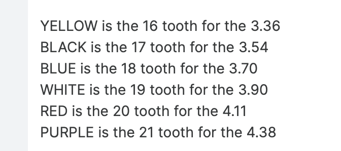
I'll count the teeth on the 75 one when I pull it - according to the linked page the white one I have is 19 teeth. Hopefully mine has only one or two more teeth than that, which in combination with the 5 speed drive gear should slow the speedo cable enough to make it more accurate at highway speeds. Wife & I tested positive for COVID at the local doc-in-abox this morning - we've been playing tag with whatever virus I got at school for the past 2 weeks, but she is in much worse shape than I. So, not much getting done car-wise, just don't have the energy. 😞 EDIT - found this - so I may as well leave the 19 tooth in, as it has 2 more teeth than the black one in my 75 with 3.54 FD
 2 points
 -
1 pointRebuilding doesn't take that long. It really depends on how deep you go and how crusty they are. Are circuits need to be cleaned and checked, new seals. Most of the rebuilders vapor hone, new zinc hardware, new gaskets, new butterflies and shafts. I would guess its about 1 hour to dissemble all 3. Then around 1 hour to put them back together very well. The other steps would depend on a bunch of factors.1 point
-
1 pointKAAZ tech replied that its a tight fit but I should be able to install the new buttons. In the mean time I found this thread: https://ratsun.net/topic/23766-k-r180-411-swap-need-help-pics/ that shows how to swap the buttons from an older R180 to a K R180. The article also references the same thread that Zed Head posted but includes more detailed information on how to separate the spider gears from the R180 to get to the buttons. Specifically, it shows where the roll pin is located that I need to drive out.1 point
-
1 point
-
1 pointFor the rest of the exhaust I got the JDM muffler https://www.datsun-zstory.com/echappements/mufflers-silencers/silencers-jdm-muffler/ The entire exhaust system came from Sean.1 point
-
This page might help on the speedo gear. https://www.thezstore.com/category/1005/speedometer-pinion-parts1 point
-
just to clarify the ease part, IIRC after removing all the drive shaft stuff so you can clearly see the tunnel, use a trans jack to support and then remove the rear mount. lower the trans (best to have removed the rad or at least have someone keep an eye on it so as the engine tilts back you do not have a fan blade dig into the rad core), until you can clearly see the shifter pin. You will have enough room to get in there with a pick and remove the circlip, pull the pin, pull up from the inside of the car the shifter, and get it secured so it does not impede the rest of the work. installing a trans with the engine in is a hit or miss prob as far as the hassle of getting the input spline to align with the clutch plate. I like to use some long bolts with the heads cut off as guide pins (I cut slots in the top to allow for a screw driver to be use to remove the bolt once trans is fitted), one on the top and one on the bottom opposite side. This lets you get the trans clocked right and in the general position. from there it's a lot of wiggle, push, swear words, then pop it just goes in. Sometimes you get lucky and it just goes in and you wonder what everybody it talking about it being a PITA. A tip is to put the trans in gear before removing the shifter, this will allow you to twist the output shaft by hand while doing the wiggle/push motion. The idea being IF your spline is just off a hair it may help it align. In reality the guide pins should be sloppy enough to let you twist the entire trans, but if the input shaft is binding up on the clutch and not in the perfect position it may resist moving to align. Being in gear gives you a bit more control over the ablity to align the input shaft. another tip, when tightening the pressure plate make darn sure the clutch alignment tool is going in straight. I can droop a bit from the weight of the friction plate. You should try to aim for a neutral position between the up and down amount of play even with the tool installed. Make sure as you go the tool can be inserted and removed easy. I have done this a few times, like I said sometimes it just pops in so easy you wonder what is the big deal, other times not so much. last tip, make sure the alignment dowels are in place, these keep the trans input shaft perfectly centered, there are 2 diag mounted I cant recall if they go in the block or the trans housing. The fit OVER the bolts in enlarged holes, so the bolts go thru them.1 point
-
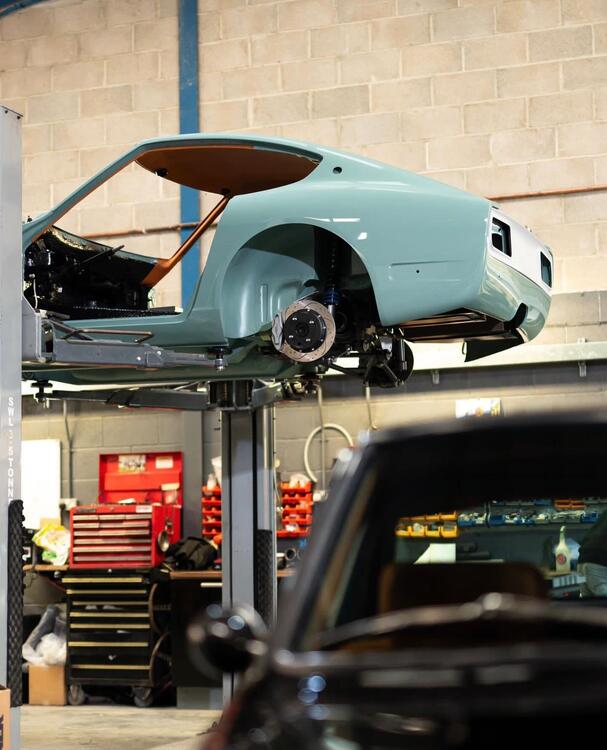
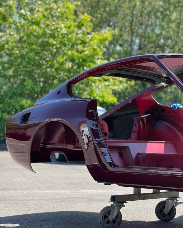
1 pointWas over in the UK last week playing with Astons and Spitfires. Went to MZR to have a look at getting a car built up. What a place, essentially they build a brand new 240Z with modern updates, think Singer Porsche but for 240Z. Amazing level of workmanship and quality, the full carbon body bonded onto the 240Z steel subframe is incredible. Henry Catchpole did a video that sums them up. Waiting list is over two years for a new build, so they must be doing something right! Here's some of the eye candy.
 1 point
 -
1 pointProblem is i've got those.. i'm missing a clean empty shell, every thing else i have spares haha! So if i could buy a shell i could start a build.. But i'm dreaming again, as my 280zx is still on the lift.. waiting for me to put the engine in... pfff..1 point
-
1 pointDepends on the RB. An RB26 was about 276BHp stock. They can make in the 400's. Supposedly about 500 HP things start to break internally1 point
-
1 pointI tried to find current pricing. The sport design was about $97,000 The evolution was starting in the $232,000 range. I suspect those numbers have gone up recently. I'm not a huge fan of the carbon fiber exterior. I have thoughts like bonding strength. Fatigue over time and how does the unit work as a whole. Layup orientation and weave. Ease of repair. Etc. I get there is some weight savings but is seems like a little more horsepower would overcome the excess weight easier than reskinning the car. Cody wants to build a crazy S30 RB powered car. I would think an RB powered MZR would be a good option if you stayed with the all metal car. I know they are working on an RB car. There would be a cost premium but even DIY it wouldn't be a cheap build. The MZR might also retain value better because of the name recognition1 point
-
1 point
-
1 pointI have done that exact thing, I was still in the garage when I started it up and it was like an oil bomb went off. There was not a square inch of surface that wasn't dripping with oil, no car show for me that day. @inline6, don't feel bad, your diff will be okay, the quality of the cast iron they used is excellent.1 point
-
1 pointHow many times have we all felt like an idiot when working on our cars? 😀 Did I ever mentioned how when I first purchased my Z I immediately changed the oil but didn't notice that the gasket from the old filter stuck to the engine so I had two gaskets. I drove around the block and wondered why there was a trail of oil leading out of my drive. Luckily a PO had installed an oversize oil pan so there was still some left.1 point
-
So you checking sounds correct. Just make sure your indicator is set at the very outside and tangential to the ring. So, from the sound of post #70 you changed two things at once and you are currently focusing on the shims at the front of the case? I had a thought, so I did some research to see if I was on the right track. I have never done a differential, so I wasn't confident in my thought process. I thought you need to set the depth of the pinion in the case and then adjust for backlash. I forgot about preload. That would be second. So it's my understanding that the shims at the front will mainly change patterning. While this will affect backlash, that's not the main purpose. The side shims are used to adjust backlash. Move the ring closer for less backlash further away for more. Here are some things I found. Take all of these with a grain of salt because alot of these are solid axles but most of the info aught to transpose. https://www.randysworldwide.com/blogs/gear-backlash https://www.yukongear.com/blogs/12-tech-tips-for-differential-assembly-setup_1 One of the main things I took away from this thread, was if you move the wear pattern, it can "sing". https://www.garagejournal.com/forum/threads/adjusting-an-old-ring-and-pinion.447201/ So I would try to keep the wear pattern as close to the original as possible. I believe as the lash goes down the heel/toe drive/coast patches will move towards the center of the tooth. Did that make sense?1 point