Alan Pugh
Free Member
-
Joined
-
Last visited
Everything posted by Alan Pugh
-
 Three hours work to make and solder new connections and job is finished. Unless you remove the covers you would never know it has been modernised.
-
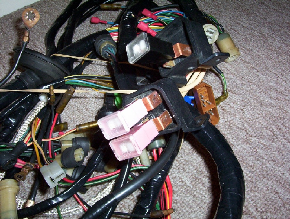
Ok, I've done the search and read the results. There are some interesting upgrades out there but none that I can find that keep and use the original holders and covers. I also need to find out the amperage of the three fusible links in my car. I think they are 1 x 80 amp (black) and 2 x 30 amp (brown). I have attached a scan of the wiring diagram, but all this shows is them numbered as #1, #3 and #4. I am currently making up some new spade connecters to either bolt or solder to the original spade connecters so that I can utilise modern cartridge type fusible links in lieu of the old style wire ones but keep the original holders and covers. I'll take pictures along the way if anyone is interested. If anyone knows the correct amperages it would be a great help. Thanks Alan. Fusible links.bmp
-
This happened to one of my cars when I was much younger, and the guy at the brake place called it bypassing. My mastercylinder had a small section of corrosion in the bore and as the seal went over this area of corrosion the fliud would bypass the seal letting the pedal go all the way to the floor. It doesn't happen all the time but gets more and more frequent as time passes. Hope this helps Alan.
-
On my old dual point set up I had 2 condensers, 1 per set of points. You don't mention how many condensers you have. I would think with only 1 you would be working it twice as hard and this would lead to failure. Just a thought.
-
Steve, The easiest way to check if it is in there is to take it to someone who specialises in brakes and get them to check. They should also have a disc in stock and this would only take them 1/2 to 1 hour. If you are confident to work on the brakes yourself, it's not a hard job. Remove the master cylinder and alloy plate from the booster. You will see the rod, seal retaining clip and seal. Remove the retainer carefully leaving the seal in place for now. Once you have the retainer out carefully pull the rod out untill it hits the back of the seal and use the rod to remove the seal at the same time as you remove the rod. There shouldn't be too much force required to do this. If the disc is not stuck to the back of the rod , or you can't see it in the recess in the diaphragm, then you have found your problem. If the disc is there then you have discounted that as the problem and we're back to square one. When working on brakes you should never reuse old components, and only do the work if you are entirely confident you can do it properly. I can't stress this enough. Alan.
-
If the reaction disc is removed the booster will still hold vacuum. It has no effect on vacuum what so ever. The disc is rubber and is about 1/4" thick, if it is not in it's proper position it shortens the length of the actuation rod simply by the rod fitting 1/4" further into the booster. The pedal travel will increase because the rod is now effectively 1/4" shorter. Another side effect is the brakes when they do take up seem to grab because you have lost the cushion effect that the rubber disc provides between the bakerlite centre section on the diaphragm and the metal rod. Hope this helps Alan.
-
This is just a best guess but have you checked that the reaction disc is in place in the booster. It fits in behind the actuator rod inside the booster. Sometimes when people change master cylinders, they will grab the rod and pull it out to check it, realise that it won't come out through the seal at the front and push it back in. This is when the rubber reaction disc falls into the bottom of the booster. Worth checking as a lot of people don't know this disc is in there. Hope this helps.
-
When I was a young bloke I owned a Ford Escort. You always knew when the uni's were starting to go in the drive shaft because they would squeak while the car was moving backwards. Universal joints are a strange animal at times.
-
Michael, I should have looked at the dates. I agree that saying it can't be done is wrong, it's more a why would you bother. I suppose the triple issue is never going to go away, next time maybe everyone should answer yeah there great do it. Then you'll get a new thread something like, I've fitted triple SU's and can't tell the differece, WHAT"S WRONG. Alan.
-
Michael, I suppose the same old info is brought up all the time because it is accurate. I owned an LJ GTR XU1 and contrary to popular opinion they did not come out with triple SU's they were infact triple Stromberg 175 CD carbs. Yes the car was very fast new, and then I fitted a set of twin 2" SU's and got the full performance out of it. There was also some head, cam and exhaust work done but the twins do flow better. If you want to fit a set of triples, fit a set of triples, but if you ask advice be prepared to read the responses you get. Alan.
-
Post #11 by Mark answers your question.
-
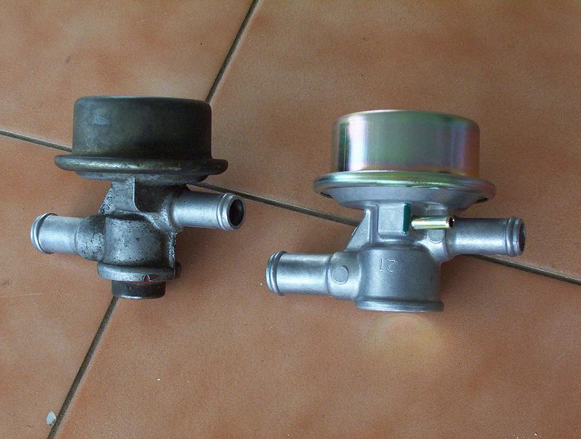
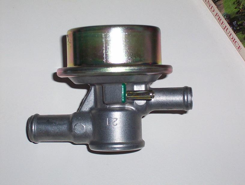
Carl, You are correct, and if you look at the diagram in the parts CD, when the valve turns 90 degrees to fit the later style the straight vacuum take off is put on the other side of the valve for that very purpose. It's easier to see when you've got the two items in your hand. Alan.
-
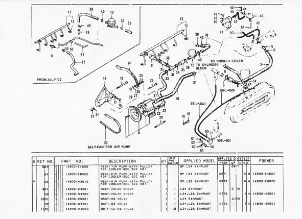
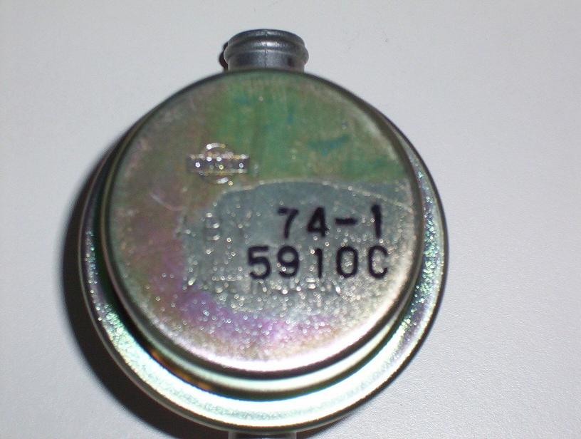
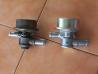
Hi Marty, Everyone, I found my old valve today and I think I (we) have solved the AB Valve mystery. On the two attached photos of my AB Valves I have shown the same side of both valves. The valves themselves are the same valve only the vacuum take off tube changes. Both valves have the same bosses both sides, it's just a mater of which side is drilled for the take off tube. The scan of the parts CD clearly shows both valves, the early car has the angled take off and the later car has the straight take off on the opposite side. Marty, I believe this means you have the correct part and mine is the one that is incorrect. Which means the original one you removed is for the later model car. I also found all my old vacuum hoses and checked them against the CD and they are exactly right for the late model fittment. As mine is a 77 model year car this all makes sense. Alan.


-
Carl, you are quite right about the part # thing with internals or some other small thing being different. The parts CD lists 2 AB Valves for L24-26. Marty's part # for L24 up to 07-72 and mine for L24-26 07-72 onwards. This is a stab in the dark but does anyone know the build date when the 240 changed to flat tops. This I believe would have required a change to the AB Valve externally. Also going along this path of thought, if the new valve did the same thing as the old, did Nissan just decide to make the newer one and box it against both part #. Alan.
-
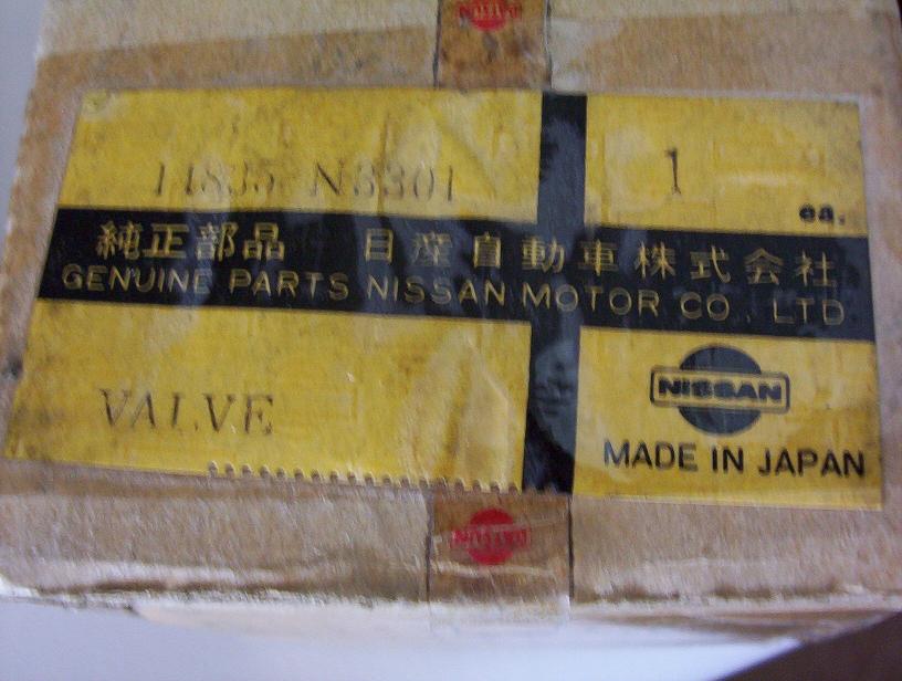
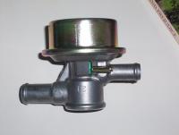
Marty, The one on the left which was removed is exactly the same as on my 77 260. (Australian car) My new one I got is nearly the same as your new one, but has a different part #. 14835-N3301. The 3 photos are my new one. I can't find the old one at the moment to take a picture but when the new one turned up I remember comparing them. Mine is not a show car so it didn't realy worry me. Alan.

-
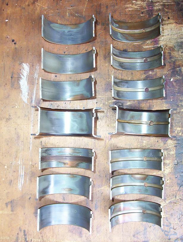
Hi Alan & Phred, Ok, i've put my glasses on (my wife yells at me all the time for not wearing them) and have come up with the correct info. Alan, yes I was going off the stamping on the back of the shell halves, they are as follows: #1 0.014 #2 0.014 #3 STD #4 0.012 #5 0.014 #6 STD #7 0.014 Each shell half also has it's own part number, the second half being E3000 for the STD shells and E3010 for the others. There is also damage to the two STD bearrings that would only happen with a clearance that was too large. This leads me to believe that the two STD shells are the mistake and the rest are the correct undersize. Phred, I measured the main bearing bore diameter in the block and it comes out at 2.3096 - 2.3097 and not the 2.3866/2.3873 that you mention. To me now, it is looking like i've got a crank with mains that are at the smaller size of the standard tollerance, even though they are still just in the standard size range. Five of the seven bearings have been running with approx 0.003 clearance and the other two with quite a bit more. It pays to wear your glasses doesn't it. Alan.

-
Hi everyone, I have stripped my engine down and found something quite confusing. I am the third owner of this car and when I bought it off the second owner it had done 175200 km (109000 miles). When the second owner bought it, it had done 42500 km and was 4 years old. To his knowledge the engine was original and had not been reconditioned when he bought it. I have confirmed through records that it is indeed the engine that the car left the factory with. When pulling the engine down all parts are Nissan and the general condition of the engine backs up what I have found out as far as being unreconditioned. Now the confusing part. The crankshaft main journals all measure up as standard along with the big end journals. Out of the seven sets of main bearing shells 6 pairs are .014 undersize and show above normal wear and 1 pair is standard showing normal wear. The undersize bearings have not damaged the crank in any way. All big end bearings are standard. Is this a mistake in the factory or has anyone else come across this before in their engine. Everything else in the engine is standard and shows the normal wear I would have expected, except for the timing chain and components which was more worn than I was expecting. I am now in the process of cleaning all components and am going to fit a standard set of mains when putting the engine back together. I would be interested to know if anyone has a theory as to why or how this could have happened. Alan.
-
I along with many others will be watching this thread with great interest. Being in Australia it is very hard to get information like this, as a lot of it is gathered by people on the ground talking to other people. To my way of thinking anything other than a boat ride to Japan and back would discount a (insert F word here) restoration. I am also very interested as to how many aftermarket parts have been used in these cars to bring them back to "as new" condition. I look forward to all the information that will be forthcoming. Alan.
-
 Hi Joseph, No i'm not planing on clear coating any of the engine components as it will put a shine on it that I don't want.
 -
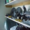
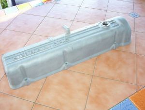
Thanks, It did come up well. It's hard to see it in the photo but the letters and raised lines are polished and the rest of the cover has been bead blasted. It gives a nice satin finish and the polished letters set it off. I did it this way as everyone seems to have a polished cover these days and it's closer to a standard looking finish.
-
-
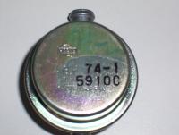
I have two oil pumps, one is off my L26 and the other is off my old L20B. The question is about the casting marks on the two of them. The one off the L26 has H23 cast in it and the one off the L20B has H33 cast into it. Are they the same pump and these are just cast numbers or does it have something to do with volume pumped? Probably a stupid question, but if someone knows the answer that would be great.
-
I have bought some stuff from Vic Brit and have done it by FAX. They don't have an email address as such, only the web order form. The FAX number is in the catalogue. I have found them great to deal with.
-
This is something to try that I got shown years ago by an old guy that worked on brakes most of his life. To check the operation of your master vac, first with the engine off depress and let up the brake pedal a number of times, until you can no longer hear any hissing of air and the pedal gets hard. Leave your foot on the brake pedal with moderate pressure and start the engine, if the master vac is sealed and working properly your brake pedal should move down as the vacuum is created inside the unit. This movement should start as soon as the engine is started. No movement or very slow movement means there is a leak in the system. Also check the one way valve (check valve) for proper operation. Hope this is of some help. Alan. P.
-
There is no doubt in anyones mind about the positioning of hand brakes except Carl's it seems. Carl why are you so insular? Cars are designed for home markets and then converted for OTHER markets. Australia has a huge muscle car following which includes many American cars, and these cars are restored or modified or whatever, but most of all they are enjoyed for what they are. With the changing laws here now in some states, collecter cars no longer have to be converted to right hand drive to be registered and driven. Not everything is made by or for the U.S.of A., there's a whole world past the horizon. Alan P.