jfairladyz
Free Member
-
Joined
-
Last visited
Everything posted by jfairladyz
-
thanks. yeah she's got some work ahead of her. The passenger side of the car isn't quite as nice as the drivers side. Some small dents, surface rust, and a missing headlight bucket. And obviously the missing bumpers. But the bulk of it is there and no apparent major rust (we'll see how accurate that statement is when I start tearing into her though ). I take delivery on the 7th. I cant wait. I've owned a couple 280zx's but never an S30.
-
This took a little longer then expected but heres a pic: Judging by the turnsignals it's definitely an early version.
-
yeah it's been a while. I've only actually had to deal with it one time and that was when I initially set my turbo motor.
-
what about where the grounds attached to the chassis? did you check and clean those?
-
-
make sure the battery grounds are clean and tight. Make sure nothings corroded and chassis grounding points are not rusted.
-
check your other thread on this subject. I posted how to adjust it in there.
-
there is a stopper screw on the passenger side of the throttle body. It threads up from underneath and is what controls how far the throttle sits open at idle. It's very small and should be a phillips head. To find it just look where the throttle linkage is stopped from rotating (in the closed position) on the throttle body. There is not a manual idle adjuster like on the non turbo models.
-
It's hard to just say which way to error. You'd need to perform a wipe pattern test to see which thickness would be best for you. Get one of each thickness and check the wipe pattern. Whichever thickness puts it the closest to the center is the one you want to go with. Test this on all the lobes to make sure you have the right size all the way down.
-
I replied in your other thread on this topic.
-
The analog is not a direct swap. You'll have to swap over the wiring harness for the gauges as well. The digi dash uses a different harness then the analog. The analog dash harness is a direct replacement however with no wire splicing or anything of that nature. Just remove the digi harness and replace it with the analog harness and plug everything back in and you're good to go.
-
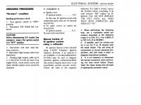
Not the whole manual but here is a PDF of the '75 wiring schematic: http://www.atlanticz.ca/zclub/techtips/wiringdiagrams/75_280z_wiring.pdf This used to be a place to get the entire manual on CD (for a price though):http://www.courtesyparts.com/Merchant2/merchant.mvc?Screen=PROD&Store_Code=CP&Product_Code=CD28075A But it appears they're temporarily out of stock. Might try calling them to see when they'll get them back in stock. The site says they're only temporarily not available due to them being updated. The CD's aren't nearly as expensive as the hardcopies that are available (the ones you can still find anyways).
-
Dont use Plasti gauge. The best (and only way IMO) is to use a micrometer to measure internal engine parts. To get a rough feel for the size of something (cross referencing parts) you can use a set of dial calipers. but dont use them for final clearance measurements. As far as seeing visual difference in the size of oversized bearings: No not while they're installed. Not unless you held them side by side to a standard size bearing to compare which was slightly larger. But at that point the bearings would be free of the engine and they should have their thickness stamped on them so you can just check that. But the best way is to measure the crank journals with a micrometer. Then measure the bores of the mains, and the rods to determine the clearance. That will tell you what size bearings you need.
-
-
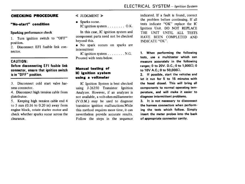
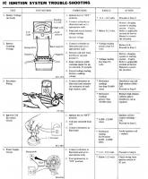
heres some pages from my FSM that outline how to test it:

-
Any pick-n-pull/pick-a-part will let you roam around for a $1 or $2. Volvos used the Bosch connectors which had the quick release feature and every time I pulled one at a junkyard it was still like new. No corrosion of the contacts and the plastic wasnt falling apart. Good parts.
-
I know this was suggested earlier but I'm gonna have to go with the valve stem seals as well on this one. Strong blue smoke on start up that fades as the motor warms is usually a tell-tell sign of this. As is the oil consumption. Try running a heavy weight motor oil to see if this remedies the smoking. That is of course only a bandaid if it helps.
-
Ok, no GR wire? No problem. Here's what you have to do. You need to run the WR wire (that would've gone to the GR) through the charge lamp and then on to an ignition hot source. If you experience run on with that setup then you simply need to install a diode into that circuit so the alternator doesnt feed the ignition after shutoff. If you want to make it really simple then just run the WR wire straight to an ignition hot source at the fuse box and put a diode inline. Without wiring up that WR to an ignition source though the alternator wont charge. If you go with the first option I outlined then you'll retain the charge indicator (if non-US were equipped with it) and if you go with the second option then you wont have a charge indicator lamp. You dont have the GR (or G or L on other models) because it was a US only feature according to a couple different schematics I went over. It led to an ignition interlock on US models (which non-US models didnt have).
-
can you make up a quick diagram of how you have it wired up as of right now?
-
wish I had a pile of parts sitting in my house like that
-
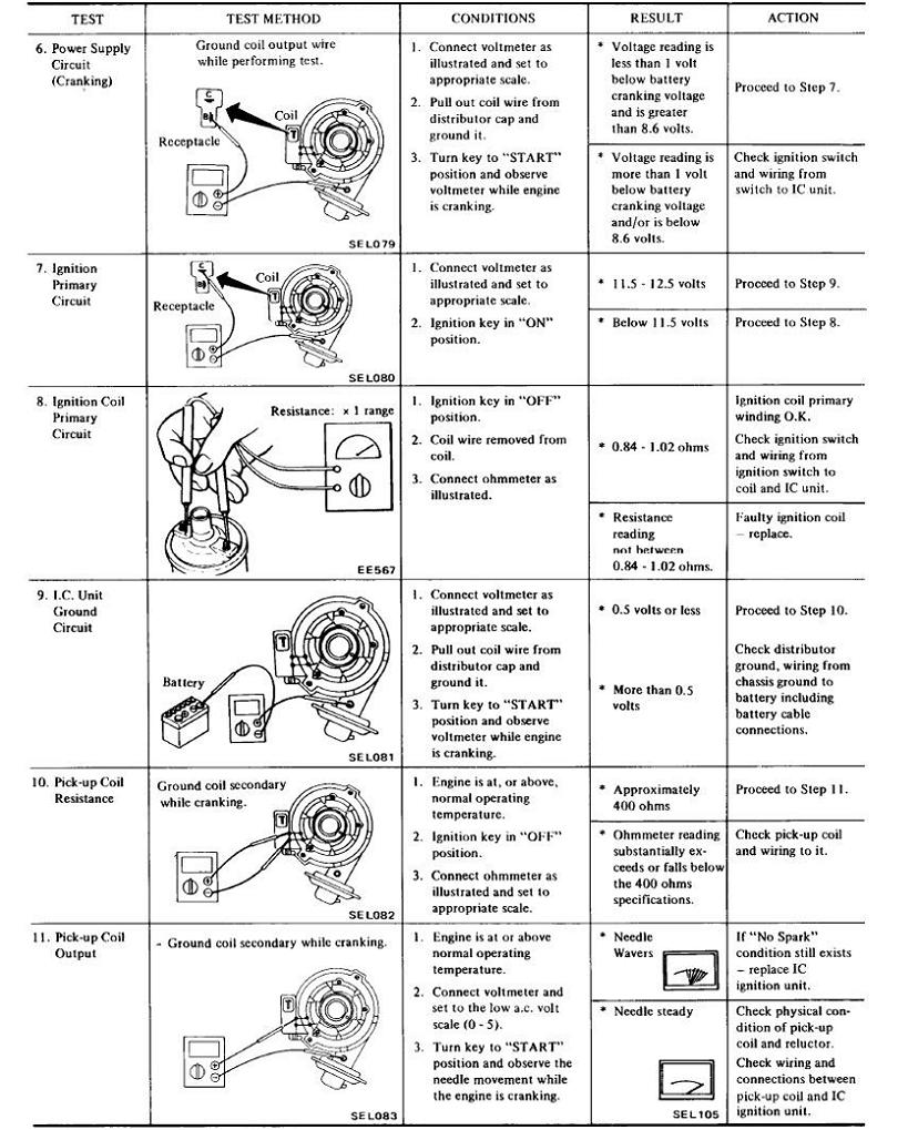
If you dont have the GR wire do you have a solid L (blue) wire? The GR wire became a solid L in later models. see attachment.

-
try www.car-parts.com
-
the orientation in the pic is the correct orientation with the engine at TDC (#1 compression). And a quick question: if its still not running then why do think your new dizzy orientation and firing order is now correct? Not flaming you, but is there something that happened after you changed all this that led you to believe things were better afterward?
-
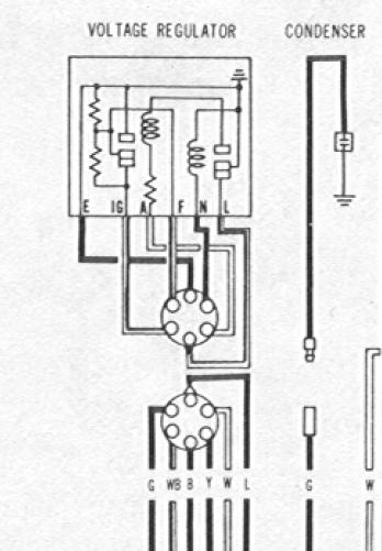
If you look at your connector though there are 8 available spots for wires. Yours only has 6 wires, but there are still 2 vacant spots. Those 2 vacant are the 2 wires that are specific to the automatic cars (so I'm assuming yours is manual, or atleast the harness is). You're missing that BW wire and that 3rd BY wire you can see in the diagram I posted.
-
Connector #1 in your list appears to be the connector for the Voltage Regulator. Connector #2 in your list appears to be the connector for the Air Conditioner Compressor Relay. Connector #3 in your list appears to be the connector for the condensor. Connector #4 in your list appears to a combo connector. This connector goes to the backup lamp sw, inhibitor sw, oil pressure sw, top gear switch. See attachement for #4.