


bloxman
Free Member
-
Joined
-
Last visited
Everything posted by bloxman
-
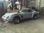
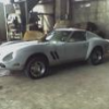 Evening Everybody, This is kinda a weird situation, or maybe not when some body explains to me what is going on? I beleive I have a 1975 280Z. The car has a Alpha GTO body kit . The VIN # is HLS30 224694 The car had doors mounted on the car and came with a spare set of doors. The mounted doors worked perfectly well open and closed using exterior door handles worked locks worked ..so cool but were rusty The mounted doors did not haved interior door pulls, or interior panels installed. Now I tried to install the "extra doors on the car as they were in better (Quantity and Quality of Rust) shape. Using the hinges that were on the car, I attempted to install the extra doors. No Fit! The trailing interior edge of the door were shaped differently. And the latching mechanism was incompatable. Could the mounted doors Have been altered for the GTO body kit? Its a damn good job if they did it! So I did a complete job on the old doors, grinding welding , great! Now based on the fact that the door bolted up but couldn't close I asummed (like an idiot) that the interior door panels would fit.....negative once again very very close but no go. For starters the door lock pull up and down thing hole on the interior panel is at 8 & 1/2 inch from trailing edge of door panel (see pic 0076). My door lock pull up and down thing is 6" from end of door? (see pic 0070) Possibly this is a pair of door s from a 2 + 2?, a 240Z , a 260Z? The latching mechanism is completely different on the doors. (see pic 0073) mounted door, (see pic 0078) extra doors. The door lock pull up and down things are mechanicaly different on the mounted doors you can see the rod travelling straight up parrallel to the back of the door. (see pic 0072) On the "extra door there is a lever involved.(see pic 0077). This is a kinda glaring difference, but in my defence was not viible with the plastic moisture bearier still in place. So I am thinking I need a new used pair of interior door panels. The "extra doors' interior panels are black with a purple or blue metal trim. There is a fella selling a pair of door panels on ebay currenty and his panels are exactly the same as mine Purple blue trim and all. He beleives they are from a 75 280Z. I suspect the answer to this problem can be solved if everbody run out into the garage with their tape measure, if your door lock pull up and down thing is around 6 inches from trailing edge of door , could ya be a pal and tell what your driving! Any body know what Year /Model I'm looking for? There is a fella selling a pair of door panels on ebay currenty and his panels are exactly the same as mine (extra doors). He thinks they are from a 75 280Z Bloxman
 -
Beandip Ah so today I went to Amazon and purchased a new rebuilt Dizzie "Cardone Industries 31-619 Remanufactured Distributor" apparently "on sale" for $150.00. It is unclear as to whether the matchbox is included. Hope mine is in good shape ,though with this distributors track record... I also snagged a Borg-Warner V578 Vacuum Advance Control, it was around Forty I figured as I 've cleaned and stripped this Dizzie to the tune of three and a half hours of my time Adding a couple of bucks to the damage of purchasing it and having it shipped International priority at this point is I know throwing good money after bad ... but should give me a spare dizzy for whatever emergency situation arrises. So my question to you is when you aquired your breaker plate was it new or used? How much was it? Where'd ya get it? Bloxman
-
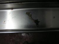
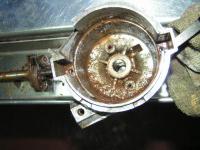
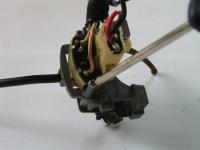
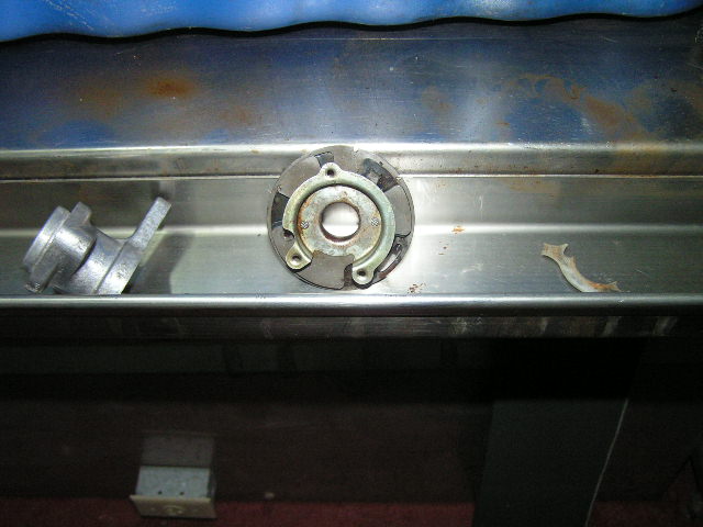
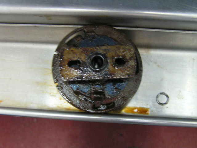
Ya Shuks! And if ya think it looks bad then here is the clincher Busted plastic triangle shaped piece that is sandwiched between the metal pieces of the breaker plate . I am reasonably sure that this means that this Dizzy is Toast as I do not know what the tolerances are in how tightthat breaker plate would need to be at the spot welds. PMO bloxman

-
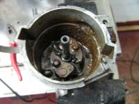
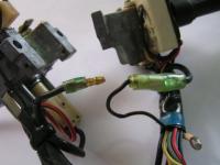
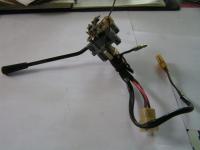
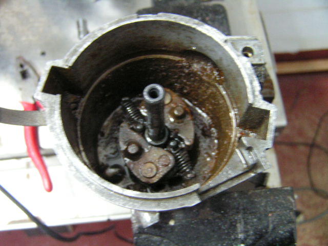
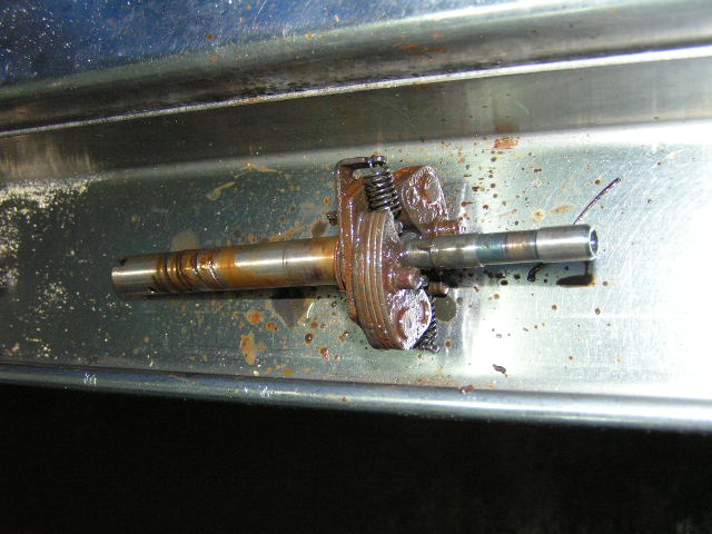
Some Photos for your Perusal Looks like this Dizzy liked fishing, or How did all this Rust get in a Alloy Distributor

 Thanks 240Z man and K steve O.K. so I feel margfinally better having heard what you said about the vacuum advance function in relation to webbers and economy. Ya economy is kinda low on my priority list. I was going to order it tonight off Amazon. Though it says it comes with the module and the Vac advance Thoughts? So based on your inputs, I'll just carve it off, ( Hack saw), the Dizzy. That should allow me to be able to remove it. Part of the problems seems to be it is inverted. When I say inverted I mean the little pipe seems to face up in all photos I have ever seen on the net, but ... mine faces down like the points dizzy. Possibly this is what busted it and maybe what has jammed it. Wish me luck Thanks again guys. Bloxman
Okey everybody chime in here I need some advice, thoughts, and recomendations. I recently Purchased a Used ZX Distributer from a member of another Club. I repeat not this club! I paid some fairly decent dough for this distributer and If you take into account where I live (Grenada, West Indies) I paid a whopping $U.S. 200.00 in shipping and it don't work! I plunked her in the whole and she would not start, close but no go. I was in the middle of attempting the rebuild on this link : http://atlanticz.ca/zclub/techtips/distributorrebuild/index.html Ah so here's the problem..it appears I got hosed eh! The vacuum advance cannister thing is screwed, I can blow right through it into the distributer , I mean Zero resistance. so the diaphram is toast, I assume it is unrepairable. So my question even really is should I even look for a vacuum advance unit new or used (maybe somebody in this club could help out) Or should I buy a "new" remanufactured one ($150.00)and pray the little module on the "screwed Dizzy is O.K. Ah just a thought a new remanufactured unit would come with the Vacuum canister right? Bloxman
Thanks 240Z man and K steve O.K. so I feel margfinally better having heard what you said about the vacuum advance function in relation to webbers and economy. Ya economy is kinda low on my priority list. I was going to order it tonight off Amazon. Though it says it comes with the module and the Vac advance Thoughts? So based on your inputs, I'll just carve it off, ( Hack saw), the Dizzy. That should allow me to be able to remove it. Part of the problems seems to be it is inverted. When I say inverted I mean the little pipe seems to face up in all photos I have ever seen on the net, but ... mine faces down like the points dizzy. Possibly this is what busted it and maybe what has jammed it. Wish me luck Thanks again guys. Bloxman
Okey everybody chime in here I need some advice, thoughts, and recomendations. I recently Purchased a Used ZX Distributer from a member of another Club. I repeat not this club! I paid some fairly decent dough for this distributer and If you take into account where I live (Grenada, West Indies) I paid a whopping $U.S. 200.00 in shipping and it don't work! I plunked her in the whole and she would not start, close but no go. I was in the middle of attempting the rebuild on this link : http://atlanticz.ca/zclub/techtips/distributorrebuild/index.html Ah so here's the problem..it appears I got hosed eh! The vacuum advance cannister thing is screwed, I can blow right through it into the distributer , I mean Zero resistance. so the diaphram is toast, I assume it is unrepairable. So my question even really is should I even look for a vacuum advance unit new or used (maybe somebody in this club could help out) Or should I buy a "new" remanufactured one ($150.00)and pray the little module on the "screwed Dizzy is O.K. Ah just a thought a new remanufactured unit would come with the Vacuum canister right? Bloxman
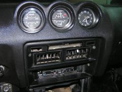
 Gauges are up and running-Thanks Alissa
 Gauges are up and running-Thanks Alissa
O.K. bedokeys So I tried on my Halloween costume.:disappoin That didn't work out , decided to go as a hockey player instead. But chickening out gave me some more time to work on the car. I got her to start after going back to basics: Took out all the plugs , cleaned them, broke # 5 , put them all back in accept # 1 position and she fired right up even with a 1/2 plug in # 1 position. Whew!! I have a Zx distributer to put in , and I didn't want to proceed further until I had the car running.....to many possibilities as to why it wouldn't start. Thanks to Mr. Camoflage & RogerZ who offered advice and recomendations Blox
I joined the White and White with red stripe that used to be connected to the Ameter portion of the Ameter / Fuel Guage. So no Joy there , though I didn't think there would be , as per our previous discussions my car has no Shunt, so the wires and plastic conecters associated with them are not connectted to anything. I am going to remove a sparkplug and see if I get a spark to jump to ground. I definately have power between the Balast resister (12V) and ground when key is in run position. I haven't figured away to connect the multi meter is such a way as I can see it and not be holding the probes when turning the key to the start position. Anyway, gotta halloween party gotta go try my costume. Bloxman
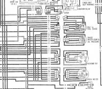
Afternoon Everyone Here is the Situation; Based on the concensus from this thread http://www.classiczcars.com/forums/showthread.php?t=23030 where everyone was such a great help , I aquired a 1978 Voltmeter / Fuel Guage from Alissa. I actually aquired all three guages. So the clock works keeps good time too! Thanks Alissa! The voltmeter works I wired in the charge light to for my alternater up grade see this link re charge light see; http://www.classiczcars.com/forums/showthread.php?t=22972&highlight=Zx+Alternator+Swap I then had to take down the fuel tank to get the sender working again so the fuel guage would work. When I wired every thing up as per those discussions Big problem the car won't start! The only thing I can think of is : Maybe the two wires (white with a red strip) and (white ) , that used to supply the Ameter needed to have been attached to one another . perhaps current flowed through them to part of the ignition circuit. were they conected some how in the Amps / Fuel guage even though I didn't have a shunt? They car always started with one bounce of the key previously. Thoughts?
Evening everyone Strait up question Can I install a Volt / fuel guage ( unknown year of Z) into my 75 280Z wiring harness as plug and play? The Volt / fuel plug is identical is identical to the Amps / fuel on the back of the guage though the wires are a different colour (scary). It was determined in a previous Thread that this was the way to go as I do not have a shunt (none came with the car) and I have done the alternater up grade to get rid of the Voltage regulator Yes I know there is a lot going on electrically! Thoughts ,encouragement , solutions would all be appreciated! Bloxman
Gauges are up and running-Thanks Alissa
O.K. bedokeys So I tried on my Halloween costume.:disappoin That didn't work out , decided to go as a hockey player instead. But chickening out gave me some more time to work on the car. I got her to start after going back to basics: Took out all the plugs , cleaned them, broke # 5 , put them all back in accept # 1 position and she fired right up even with a 1/2 plug in # 1 position. Whew!! I have a Zx distributer to put in , and I didn't want to proceed further until I had the car running.....to many possibilities as to why it wouldn't start. Thanks to Mr. Camoflage & RogerZ who offered advice and recomendations Blox
I joined the White and White with red stripe that used to be connected to the Ameter portion of the Ameter / Fuel Guage. So no Joy there , though I didn't think there would be , as per our previous discussions my car has no Shunt, so the wires and plastic conecters associated with them are not connectted to anything. I am going to remove a sparkplug and see if I get a spark to jump to ground. I definately have power between the Balast resister (12V) and ground when key is in run position. I haven't figured away to connect the multi meter is such a way as I can see it and not be holding the probes when turning the key to the start position. Anyway, gotta halloween party gotta go try my costume. Bloxman
Afternoon Everyone Here is the Situation; Based on the concensus from this thread http://www.classiczcars.com/forums/showthread.php?t=23030 where everyone was such a great help , I aquired a 1978 Voltmeter / Fuel Guage from Alissa. I actually aquired all three guages. So the clock works keeps good time too! Thanks Alissa! The voltmeter works I wired in the charge light to for my alternater up grade see this link re charge light see; http://www.classiczcars.com/forums/showthread.php?t=22972&highlight=Zx+Alternator+Swap I then had to take down the fuel tank to get the sender working again so the fuel guage would work. When I wired every thing up as per those discussions Big problem the car won't start! The only thing I can think of is : Maybe the two wires (white with a red strip) and (white ) , that used to supply the Ameter needed to have been attached to one another . perhaps current flowed through them to part of the ignition circuit. were they conected some how in the Amps / Fuel guage even though I didn't have a shunt? They car always started with one bounce of the key previously. Thoughts?
Evening everyone Strait up question Can I install a Volt / fuel guage ( unknown year of Z) into my 75 280Z wiring harness as plug and play? The Volt / fuel plug is identical is identical to the Amps / fuel on the back of the guage though the wires are a different colour (scary). It was determined in a previous Thread that this was the way to go as I do not have a shunt (none came with the car) and I have done the alternater up grade to get rid of the Voltage regulator Yes I know there is a lot going on electrically! Thoughts ,encouragement , solutions would all be appreciated! Bloxman
 Any body know the Rim sizes and offsets for the ALPHA gto ,Rhino GT kits ? The turnkey cars were equipped with Dayton wire wheels and I see they are currently offloading rearwheel drive spoke rims for cheap on ebay. But the vendors are not the most helpfull people . They told me to take my car to a tire shop to find out what I wanted. any help will be appreciated Bloxman
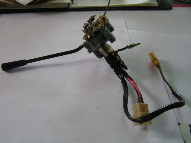
Addition photos as promised. Gotta go its sunday suppossed to be family time. Later
Any body know the Rim sizes and offsets for the ALPHA gto ,Rhino GT kits ? The turnkey cars were equipped with Dayton wire wheels and I see they are currently offloading rearwheel drive spoke rims for cheap on ebay. But the vendors are not the most helpfull people . They told me to take my car to a tire shop to find out what I wanted. any help will be appreciated Bloxman
Addition photos as promised. Gotta go its sunday suppossed to be family time. Later
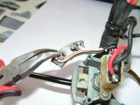
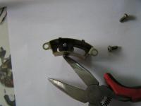
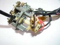

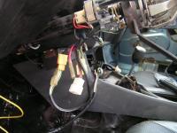
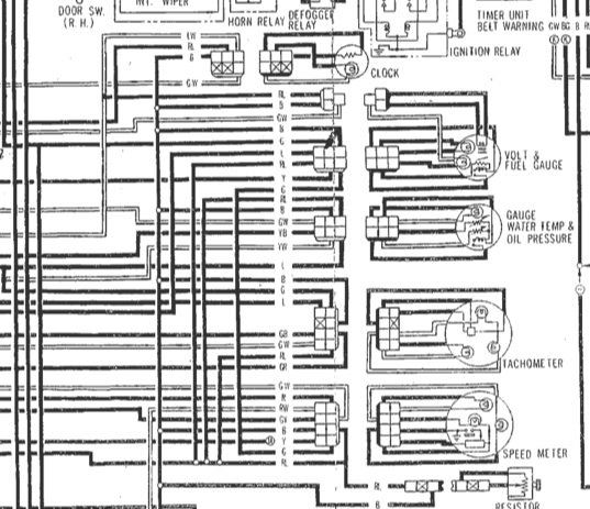
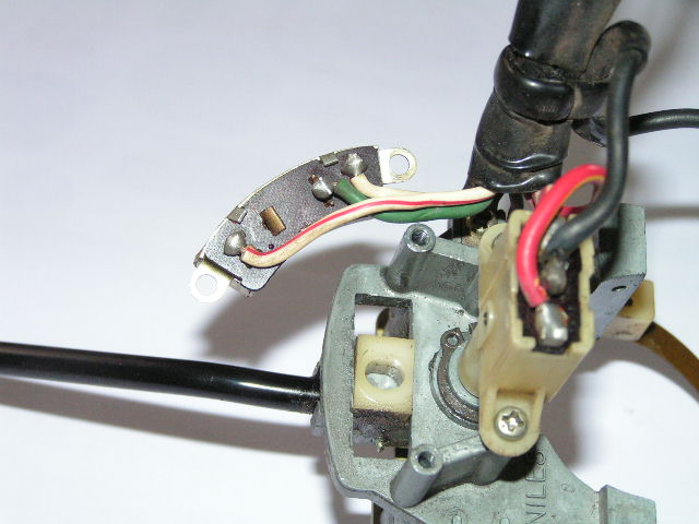
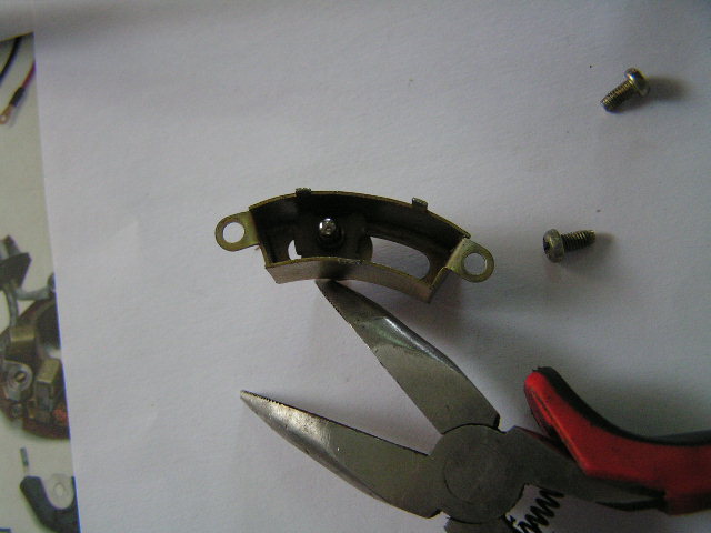
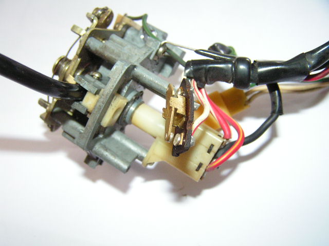
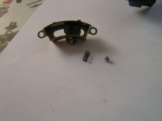
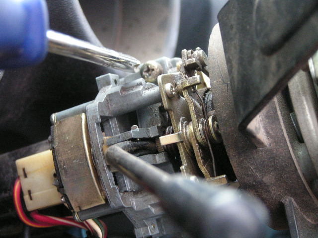
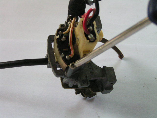
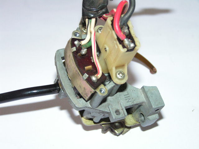
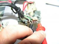 O.K. so I number them in a sensible manner unfortunately I can only do it ten at a time so.. Check next link I may need some help in The wording for the step by step. Step 1 remove the screws located on bottom of combination switch cover (don't actually have a photo of this ) I din't actually have a bottom half of the cover. Remove the top half of cover (lift up and pull towards you) Step 2 examine all connecters below steering column . You could just take them apart if "nobody" has ever "fixed" them before. mine are apparently stock and there is no way you could hook them back together wrong (zzzt!) Step 3 Undo all the connecters Step 4 Undo two phillip head screws on left side of combination switch (I recomend undoing bottom first but suit your self. support comb switch after bottom screw is removed first...so it doesn't fall off the steering column when top screw comes out. Step 5 take switch to your workplace. you will need small phillips screwdriver , offset needle nose pliers , sand paper or emory cloth , a really small flat blade screwdriver (headlight dimmer switch portion), can of contact cleaner spray , some wd 40. step 6 disconnect black wire coupling the headlight switch from the turn signal switch Step 7 remove two srews holding turnsignal sitch to turn signal combination switch assembly. pull up gently to seperate switch from assembly. Step 8 pry metal tabs (using offset needle nose pliers), up so as to free the guts from metal shell. Pull gently on wires (yes the wires) to remove brown board looking thing wires are soldered to from the metal shell. you should see a set of points (kinda looks like a teeter totter on the back side of the brown board where the wires are soldered. and the metal shell has a sping and a ball bearing. The ball bearing sits on top of the spring. The spring sits in a little cylindrical receiver (hole). Step 9 sand both sides of both contacts on the points. Step 10 clean the ball Step 11 clean the spring step 12 very carefully stretch the spring a little bit (do not bust it) Step 13 put spring back in whole Step 14 put ball bearing back on spring Step15 while supporting Metal shell with spring and ball bearing in a vertical manner, push beautifully cleaned teeter totter points thing back inside metal shell. Step 16 while holding the shell and the teeter totter together and not releasing tension (so as to let ball bearing fall inside) bend the three metal tabs back into position. Step 17 reinstall using two little phillips screw you removed Step 18 Check for continuity (with a digital multimeter) set to "sing" ,sorry I cannot explain this any better ,but if you touch the two multi meter probes together the "sing". 18 a put turn signal switch in neutral position (neither right nor left turn) Touch one multimeter probe to the middle soldered wire (mine is green) touch other probe to wite wire with red stripe. no noise Good! Now touch the white with a black stripe no noise? good! now manipulate the turn signal to a left turn replace probe to middle wire and touch one of the other wires , Something had better sing. Repeat for right turn signal position. next installment (maybe later tonight or tommorrow morning) the headlight dip switch. additional photos in next thread
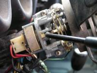
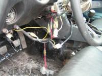

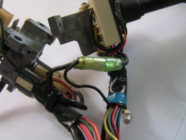
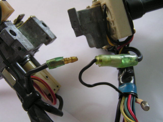
 Evening everyone! Thought I'd like to share what a great Z day I had. Went to work when nobody was in the shop and took the combination switch apart and got my turn signals working again. Took some photos (like maybe ten to fifteen) close up with a good quality digital. Is their any place specific I should post these and the info I have garnered? Thought perhaps folks might be interested. I would have been interested in a step by step with photos , they were a Ba$#@%& , starting from scratch. I've had 'em apart about three times now to get everything working. Probably know all I'm ever gonna about what goes on inside there. Thoughts, recomendations ? I'm not trying to blow my own horn (har!), honestly Bloxman
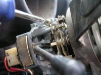
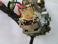
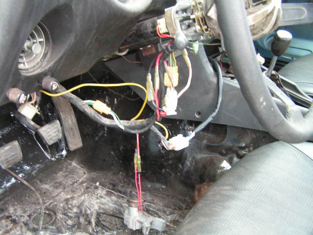
Well today is your lucky day. I pulled apart my turn signal headlight dip switch in my 1975 280Z today as the brights were not working and my turn signals not working. I was successfulin getting the brights workin (lights) no turn signals though. I haven't given up though its just not the combination switch in that instance. So I can probably help (advise) : 1)Yada yada usual safety stuff remove positive battery terminal. 2)Remove sterring wheel facia by undoing screws located beneath. 3)undo all clips below combination switch.. don't worry their kid proof. I think their was seven of them.You cannot connect a black to a red as they are male /female conections. 4)remove two screw that hold combination swith to steering shaft. the screws are kinda on the left side running horizontal and are phillips heads. 4b)there is a black pair of connecters holding lights portion and turn signal portion of combination switches together. examine and remove the one black wire necesry to accomplish this. Turn signal/dip switch 1) Remove the two screws that hold the long white plastic switch. (To determine which of the two switches I refer to; pull back on lever like you wanted to turn on the brights.observe . With the two screws removed withdraw the white plastic shaft (without bending) all the way out. on the square end with the wires there are four tabs you must gently pry open loose (free). (really,really small flat blade screwdriver) pull up(very gently), so as not to undo solder, on wires. Look on bottom side when removed from white plastic examione the bits that look like a twin set of rocker points, (looks kinda like a a teeter totter) . Insert a fine bit of sandpaper or emory cloth between the contact surfaces. Do both sides of both contact surfaces. Scrape, little wire brush, emory or sand paper the back side of the teeter totter as well as this is the power inlet. . now look down in the other bit of the switch. There should be a little brass thing (tip) . If its green Clean it. Then spray some wd40 in it for lubrication its an accentric cam they like lubrication (a little wee bit). invert the points thing back into the switch and replace the two screws. reinstall the combination switch in reverse order. connect battery, turn on lights . voila Whats happening; The dip switch is a two way acccentric cam driven switch: either low beams or high beams. if the teeter totter is inclined one way it sends power to the high beams, if its inclined the other way power is to the lows. every time you pull back on the turn signal its reverses the position. If this is far too wordy and unclear I would be willing to take it apart again tommorrow step by step with decent photos. Bloxman
just on the off chance, 'cause everything else is sounding so good... How about an exhaust manifold leak. I had an experience once where the ticking increased with rpm and the ticking got louder as the engime warmed up... Sounded exactly like bad tappets . Turns out the previous owner of my car had replaced the exhaust manifold gasket and never tightened it really passed hand tight. As soon as I tightened everything up the engine was a cracker! Bloxman
Mike w Whew I won't make that mistake again. Holly cow ! My inbox is full from members who had time to see the email posting on my thread,and cared enough to warn me of my mistake thanks guys! Anyway so obviously in future I will ask people to send me a private Mesage in order to get my email address. Thanks for caring Bloxman
Zup Thank you for thinking of me but , the consensus is was a few replies back that if I install a shunt it will be done in a matter of seconds as I have done the Alternater upgrade, and thus I will have to go the voltmeter route. Thanks for thinking of me and if you ever need to get ahold of me check my profile my email is there Apparently I can not post it in the forumn as the forumn is open to the public you can get this also on my profile. Bloxman
Whenever I am looking for top dead center I remove the spark plug and use a long piece of gas welding rod to determine top dead center. While you are doing this have the distributor cap off and see if the rotor is pointing at the #1 position at the sme time your welding rod seems to make its zenith in travel. Then check that your plug wires seem to be in the right order. You can generally fab up a pointer figure out where the old one used to bolt up. do the process above with the rod and rotor and mark (cut it , scrape it ,use a file whatever works best for you) it it to the timing mark. Bloxman
sblake01 O.K well I'll have to think on all this for a while. Many options (voltmeter, fuel guage ,and /or combinations. Maybe I'll end up putting new gauges in completely. I mean if I need to know what time it is (the clock) I could look at my watch. That would free up a whole! So in Summation the concensus is as I have replaced the Alternator then I would have burned the fuses in the shunt(if I had a shunt) and the Ammeter would have stopped working and I would have had to replace it with a Voltmeter. So Proceed to step 2 decide on which Voltmeter/ voltmeter/fuel guage i want. Just a thought... Will the Factory fuel guage work if the Ammeter is not getting power? Thanks for continuing to look for the shunt Buddy Bloxman
V8-240Z You said "replaced the 45-45 amp meter with a volt meter from a 77-78 280Z. Any of the high output alternator conversions will overload the stock shunt and burn it out like a fuse. The Voltmeter swap was a bolt in. O.K. so I have done the Alternater conversion already so what are we thinking now that I should remove the ammeter and replace it with a Voltmeter? Do I join the thicker white with red trace wires together if I do thus are just isolate them?
sblake01 You said His car is a 75 280Z which, If I knew where to look on the car for the shunt, I could try to find one for him on my next junkyard trip since I think they have a 75 at the local Pick a Part. I'm touched you guys(Z car club Members) and You personnally ROCK! What a kind offer! The only thing I know about the location is what I posted from the original thread .I copied it from the only relavent thread that the seach found using "shunt". that menmber said" on my 75-280 I only have 1 fusible link box, located on the relay bracket. Underneath this box, is a metal box, 2" x 2" x 6" and it contains a copper strip, shaped like a "m", and 2 glass fuses. 2 large gauge wires ( 8ga maybe ) one white and one white/red connect to the large metal strip, and 2 light gauge wires, same colors, connect to the 2 glass fuses." Thanks sblake01
Evening everyone! Thought I'd like to share what a great Z day I had. Went to work when nobody was in the shop and took the combination switch apart and got my turn signals working again. Took some photos (like maybe ten to fifteen) close up with a good quality digital. Is their any place specific I should post these and the info I have garnered? Thought perhaps folks might be interested. I would have been interested in a step by step with photos , they were a Ba$#@%& , starting from scratch. I've had 'em apart about three times now to get everything working. Probably know all I'm ever gonna about what goes on inside there. Thoughts, recomendations ? I'm not trying to blow my own horn (har!), honestly Bloxman
Well today is your lucky day. I pulled apart my turn signal headlight dip switch in my 1975 280Z today as the brights were not working and my turn signals not working. I was successfulin getting the brights workin (lights) no turn signals though. I haven't given up though its just not the combination switch in that instance. So I can probably help (advise) : 1)Yada yada usual safety stuff remove positive battery terminal. 2)Remove sterring wheel facia by undoing screws located beneath. 3)undo all clips below combination switch.. don't worry their kid proof. I think their was seven of them.You cannot connect a black to a red as they are male /female conections. 4)remove two screw that hold combination swith to steering shaft. the screws are kinda on the left side running horizontal and are phillips heads. 4b)there is a black pair of connecters holding lights portion and turn signal portion of combination switches together. examine and remove the one black wire necesry to accomplish this. Turn signal/dip switch 1) Remove the two screws that hold the long white plastic switch. (To determine which of the two switches I refer to; pull back on lever like you wanted to turn on the brights.observe . With the two screws removed withdraw the white plastic shaft (without bending) all the way out. on the square end with the wires there are four tabs you must gently pry open loose (free). (really,really small flat blade screwdriver) pull up(very gently), so as not to undo solder, on wires. Look on bottom side when removed from white plastic examione the bits that look like a twin set of rocker points, (looks kinda like a a teeter totter) . Insert a fine bit of sandpaper or emory cloth between the contact surfaces. Do both sides of both contact surfaces. Scrape, little wire brush, emory or sand paper the back side of the teeter totter as well as this is the power inlet. . now look down in the other bit of the switch. There should be a little brass thing (tip) . If its green Clean it. Then spray some wd40 in it for lubrication its an accentric cam they like lubrication (a little wee bit). invert the points thing back into the switch and replace the two screws. reinstall the combination switch in reverse order. connect battery, turn on lights . voila Whats happening; The dip switch is a two way acccentric cam driven switch: either low beams or high beams. if the teeter totter is inclined one way it sends power to the high beams, if its inclined the other way power is to the lows. every time you pull back on the turn signal its reverses the position. If this is far too wordy and unclear I would be willing to take it apart again tommorrow step by step with decent photos. Bloxman
just on the off chance, 'cause everything else is sounding so good... How about an exhaust manifold leak. I had an experience once where the ticking increased with rpm and the ticking got louder as the engime warmed up... Sounded exactly like bad tappets . Turns out the previous owner of my car had replaced the exhaust manifold gasket and never tightened it really passed hand tight. As soon as I tightened everything up the engine was a cracker! Bloxman
Mike w Whew I won't make that mistake again. Holly cow ! My inbox is full from members who had time to see the email posting on my thread,and cared enough to warn me of my mistake thanks guys! Anyway so obviously in future I will ask people to send me a private Mesage in order to get my email address. Thanks for caring Bloxman
Zup Thank you for thinking of me but , the consensus is was a few replies back that if I install a shunt it will be done in a matter of seconds as I have done the Alternater upgrade, and thus I will have to go the voltmeter route. Thanks for thinking of me and if you ever need to get ahold of me check my profile my email is there Apparently I can not post it in the forumn as the forumn is open to the public you can get this also on my profile. Bloxman
Whenever I am looking for top dead center I remove the spark plug and use a long piece of gas welding rod to determine top dead center. While you are doing this have the distributor cap off and see if the rotor is pointing at the #1 position at the sme time your welding rod seems to make its zenith in travel. Then check that your plug wires seem to be in the right order. You can generally fab up a pointer figure out where the old one used to bolt up. do the process above with the rod and rotor and mark (cut it , scrape it ,use a file whatever works best for you) it it to the timing mark. Bloxman
sblake01 O.K well I'll have to think on all this for a while. Many options (voltmeter, fuel guage ,and /or combinations. Maybe I'll end up putting new gauges in completely. I mean if I need to know what time it is (the clock) I could look at my watch. That would free up a whole! So in Summation the concensus is as I have replaced the Alternator then I would have burned the fuses in the shunt(if I had a shunt) and the Ammeter would have stopped working and I would have had to replace it with a Voltmeter. So Proceed to step 2 decide on which Voltmeter/ voltmeter/fuel guage i want. Just a thought... Will the Factory fuel guage work if the Ammeter is not getting power? Thanks for continuing to look for the shunt Buddy Bloxman
V8-240Z You said "replaced the 45-45 amp meter with a volt meter from a 77-78 280Z. Any of the high output alternator conversions will overload the stock shunt and burn it out like a fuse. The Voltmeter swap was a bolt in. O.K. so I have done the Alternater conversion already so what are we thinking now that I should remove the ammeter and replace it with a Voltmeter? Do I join the thicker white with red trace wires together if I do thus are just isolate them?
sblake01 You said His car is a 75 280Z which, If I knew where to look on the car for the shunt, I could try to find one for him on my next junkyard trip since I think they have a 75 at the local Pick a Part. I'm touched you guys(Z car club Members) and You personnally ROCK! What a kind offer! The only thing I know about the location is what I posted from the original thread .I copied it from the only relavent thread that the seach found using "shunt". that menmber said" on my 75-280 I only have 1 fusible link box, located on the relay bracket. Underneath this box, is a metal box, 2" x 2" x 6" and it contains a copper strip, shaped like a "m", and 2 glass fuses. 2 large gauge wires ( 8ga maybe ) one white and one white/red connect to the large metal strip, and 2 light gauge wires, same colors, connect to the 2 glass fuses." Thanks sblake01


Important Information
By using this site, you agree to our Privacy Policy and Guidelines. We have placed cookies on your device to help make this website better. You can adjust your cookie settings, otherwise we'll assume you're okay to continue.