zKars
 Subscriber
-
Joined
-
Last visited
Everything posted by zKars
-
 I ALWAYS crazy glue the reaction disk to the piston when I take these things apart. No way I’m ever losing that thing again...
 -
If you aren't watching the final minutes of this you should be..... https://bringatrailer.com/listing/1972-datsun-240z-127/?utm_source=transactionalemail&utm_medium=email&utm_campaign=bat_watched_listing_ending_soon
-
I have a bunch of old used racks if you can’t find something closer.
-
Something very appealing about torquing on the flywheel with a starter gear and the mechanical torque multiplier advantage you get with a 9:190 or whatever the flywheel tooth count is. A big bad thick plate you bolt on in place of the starter, bearing mounted 1” or so shaft with a starter gear on one end, 1/2 or 3/4” drive square on the other end. Shouldn’t need all that long a ratchet handle to put very considerable torque on the crankshaft. Probably more costly and complex to make for such an occasional use tool.... Keep working on the crank nut. Still the most elegant solution.
-
Forget my lock nut idea. Any torque requirement that busts a damper like that is way beyond a lock nut, and might beyond the M16 bolt shear strength.
-
Clearly there is a torque limit to this method that may very well not be enough for all locked up motors. It’s just a real simple and inexpensive first attempt before moving on to more forceful and expensive methods.
-
I like the chain wrench idea with an old timing chain. It does require you take off the front cover. How about this? I’m assuming the problem with using the regular crank bolt is that it can’t be used to apply CCW torque or it just comes loose, so... About investing in a M16x1.5 nut and using that to lock the bolt to the crank snout, then using your regular socket on the bolt head? Yes you have to invest in a 27mm open end wrench. I wonder how much torque that would take to back that off? Depends on how much torque you apply to tighten that nut. The only M16x1.5 nut on the car I know of is the steering wheel lock bolt, but its pretty thin. I’d rather use a full width nut. Maybe a flange nut?
-
The engine bay does have that “post 75” look doesn’t it? If the head is an N47 rather than the expected N42 on a 75, then.... With the many years of history, who knows what parts have been substituted in. The only concern I have is the plastic fuel filter back by the tank, but only if its on the output side of the pump. If its between the tank and the pump inlet, it’s under no pressure (vacuum actually) and should be fine. If its there, then there has to be another proper high pressure EFI filter under the hood between the Body hard line from the tank and fuel rail at the front right of the engine. Heat soak is rarely an issue with EFI engines. I’m leaning on the ignition module failure as the likely cause. Or coil, or distributor pickup heat related failure.
-
This is the short ear, single exhaust hanger bracket so its the early ZX tranny, not the later tall ear single bracket “close ratio”. 80-81 year range. The forward-most hole, “C”, is the reverse light switch position. Can’t say for sure what the others are easy to test. See what gear positions cause the switches to change from “open” to “close”. Some may be normally open, some normally closed. Just look for a change of state when in Only one of the gear positions. I’ve never been clear on what models/markets/year ranges etc determine the existence of neutral and/or high gear switches. Most north american ZX trans I’ve seen only have the reverse switches. Early Z trans often have a neutral switch. Zed’s drawing shows all three with two different positions for the OD (top gear) switch. Haven’t seen a definitive listing anywhere.
-
Front of trans is to the left

-
i'll split it with you. I think we both get half of nothing...
-
Yup post is gone. Hope it stayed nearby. I'll ask him
-
I kinda decided I would not spill any beans. The owner didn't include it in the ad, must have had his reasons. Let’s just say it’s not a 69....
-
Don’t forget good old powder coating. Lots of shiny, chrome, aluminum and silver options out there. What I like best is the toughness of the coating to resist the inevitable foot and boot rubbing abuse these things take.
-
Here is one picture I took back in April when I saw it.
-
The only “thing” I spotted, and he does mention it in his ad, is that it was repainted, “A decade” ago, but it was repainted without removing glass/weatherstrip etc which is easy to spot. The repaint is one of the best I’ve seen in terms of color match and correct sheen/finish/look/feel. You’d swear it was original paint in outstanding condition. Everywhere I looked on the car, (over a relatively short period of time, I did not study every inch), everything looked correct for the VIN. I was there trying to sell him a Z, which, after I saw what he had (and picked my jaw up from the ground after seeing this Z), we spent of our time on, shall we say, “sales craft”.... Turns out he was looking to replace this one with more of a driver quality car. And here we are with this one for sale. I will gladly go and look at it for anyone who wants to get more detail or my opinion, and give it more careful look over. I’m sure the owner will have no problem with this.
-
i've seen it. It is amazing.
-
That door is definitely for 77-78 280, 2 seater. Definitely not 2+2, which is MUCH longer overall. The earlier doors are totally different internally, latches etc, as is the window frame, there is no way this door could have an earlier window frame, they don’t mount the same way. This door appears correct for your 78. This does not help you much as to why this door does not fit your car. Perhaps we need to see the door on, so we can see exactly how far out it is, how and where.
-
I’ve seen too many glass fuses that look great, even test great, but if can twist either end cap even a little bit then it’s got a crappy internal connection that is about to fail.
-
In the 2 or 3 I've done so far, the amount of suction is spectabulus (yes I invented a word, no beer involved) so there is no problem with getting fuel from tank with an air filled line. Only time will tell about real world performance and life. The only thing I screwed up was getting the check valves in the right way the first time. And maybe the second....
-
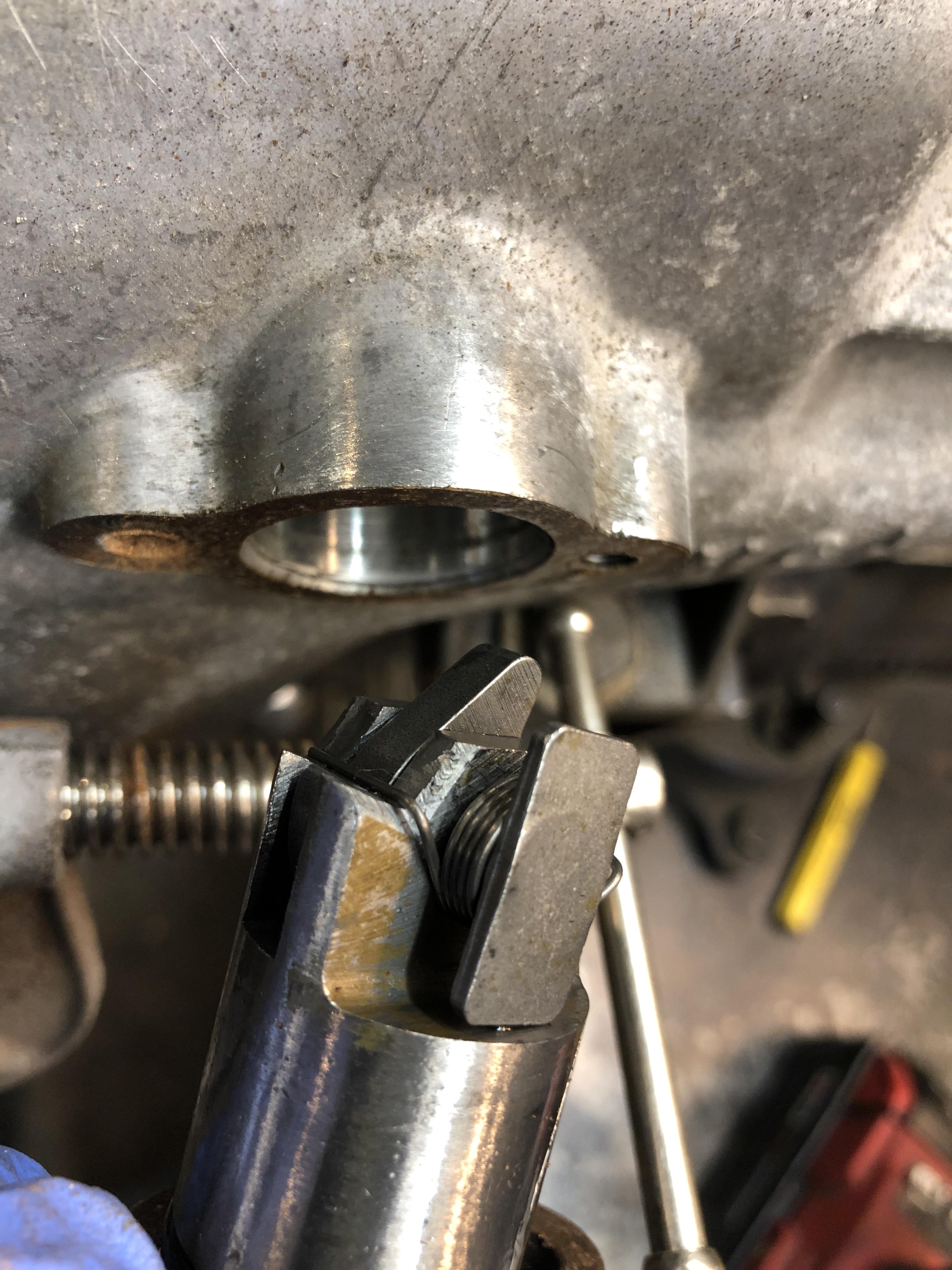
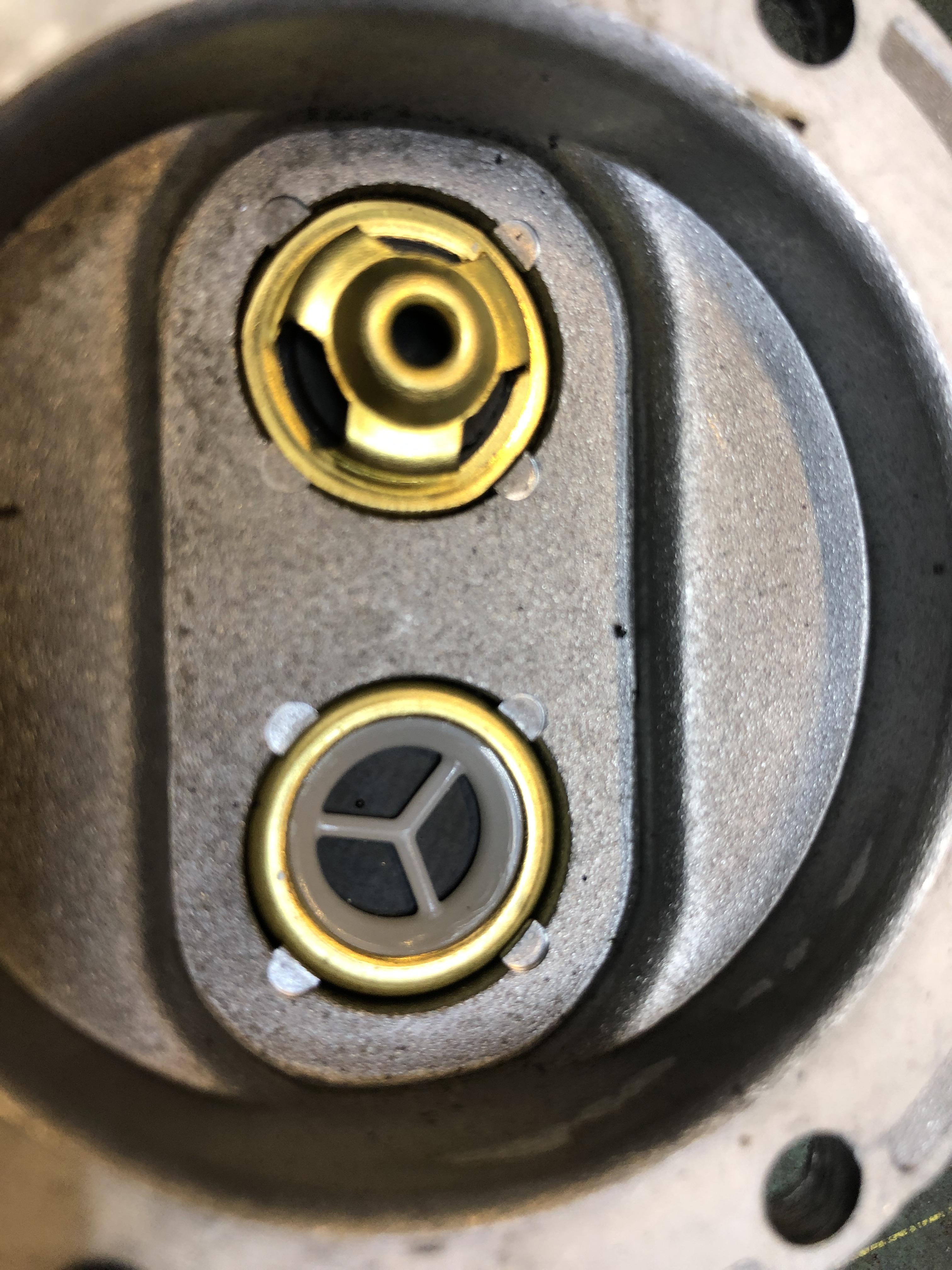
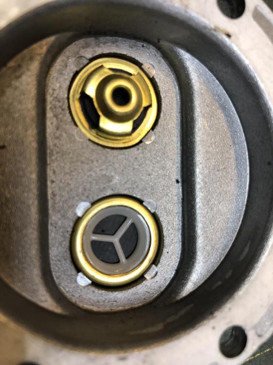
The last "gotcha" is the tiny thin seal washer between the check valve and its seat in the housing. I was able to remove virtually NONE of the OEM ones. They were hard and stiff and stuck in real well. They were easy to scrap out, but were always destroyed in the process. So you may need to source or make some new ones. 3/4 OD (19mm) and about 18mm ID. Only about 0.05 thickness. A tiny ring of RTV would do as well.... You want that check valve sealed to the housings. NO LEAKS ALLOWED around the check valves.
-
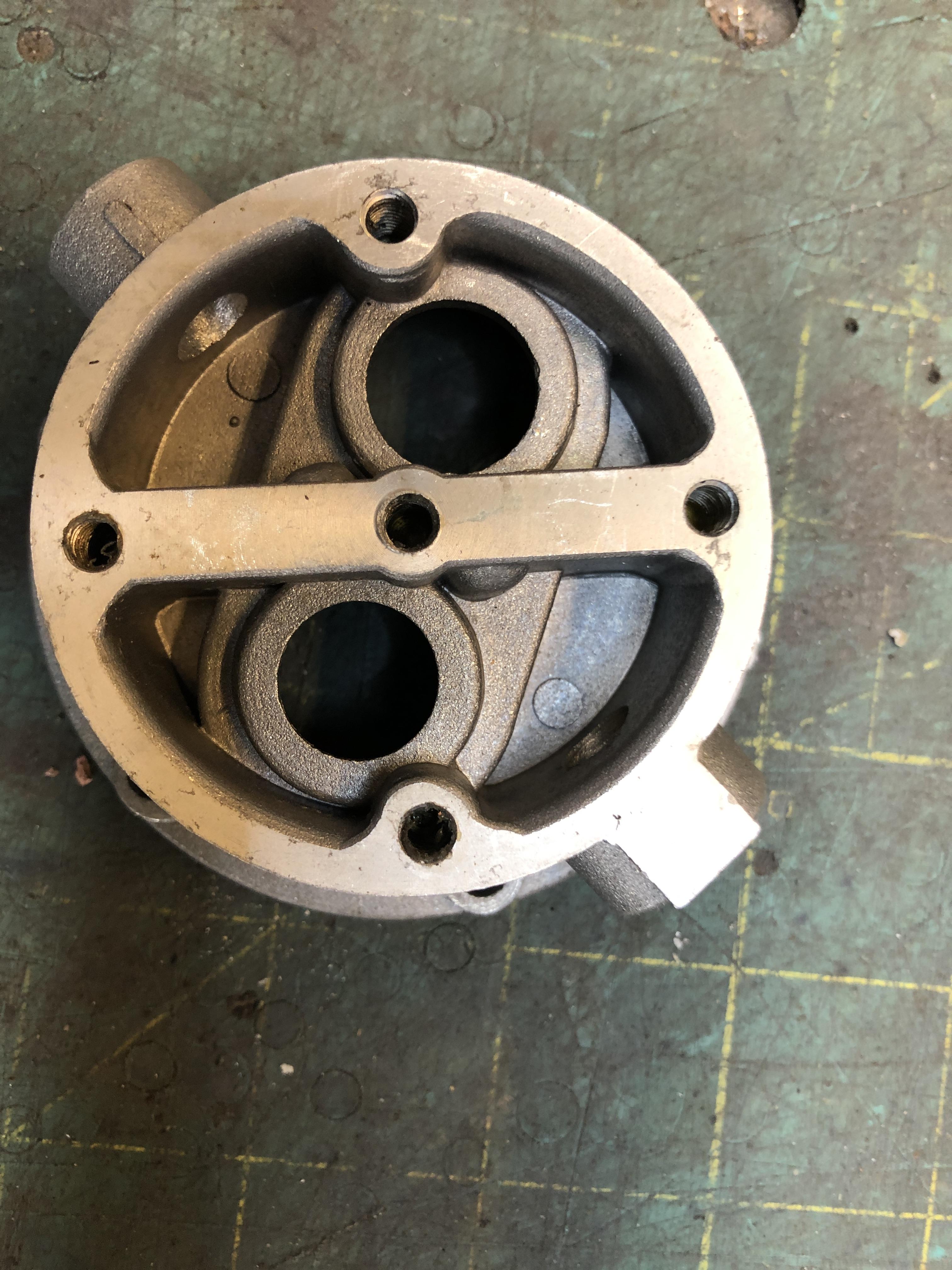
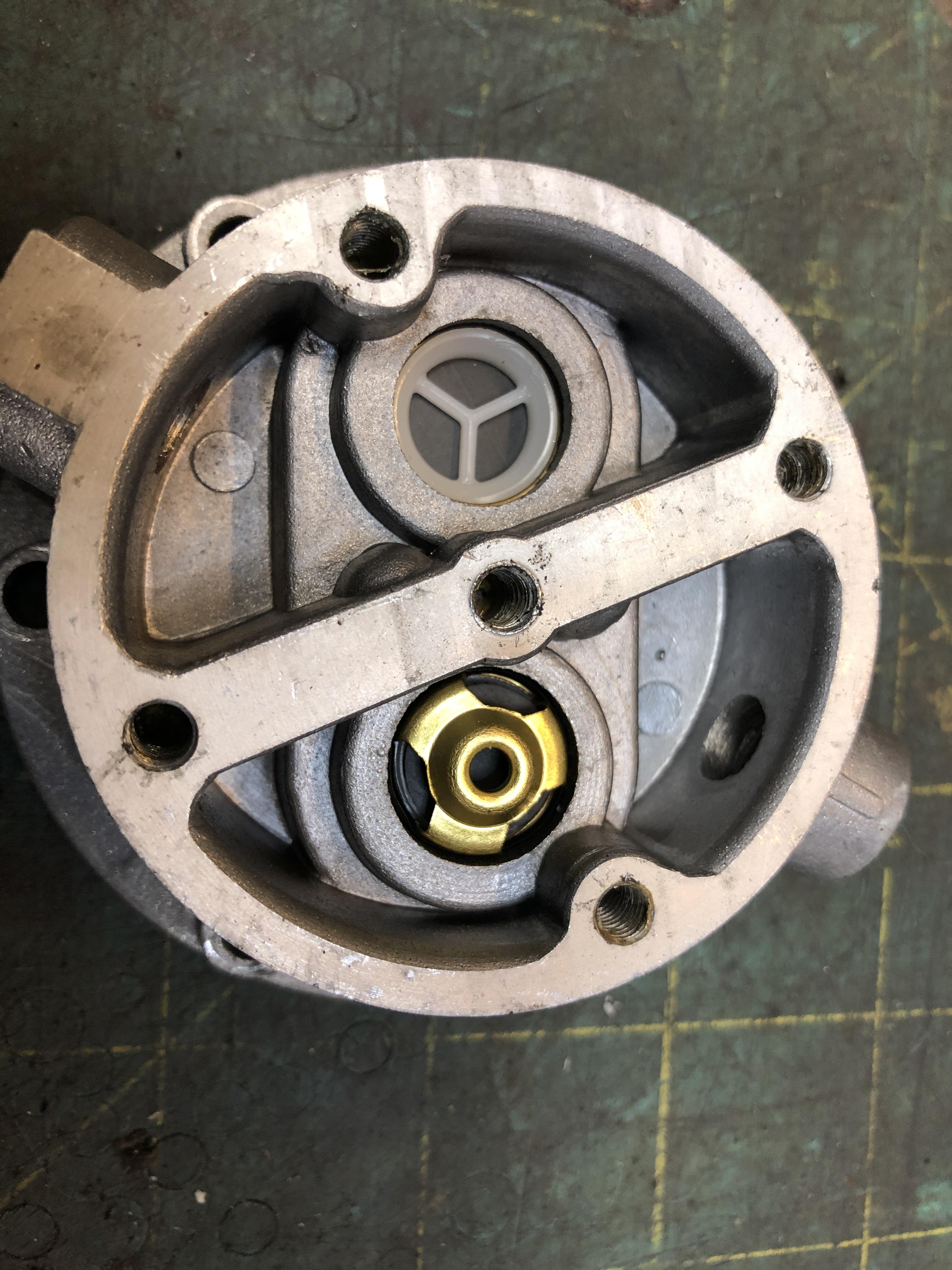
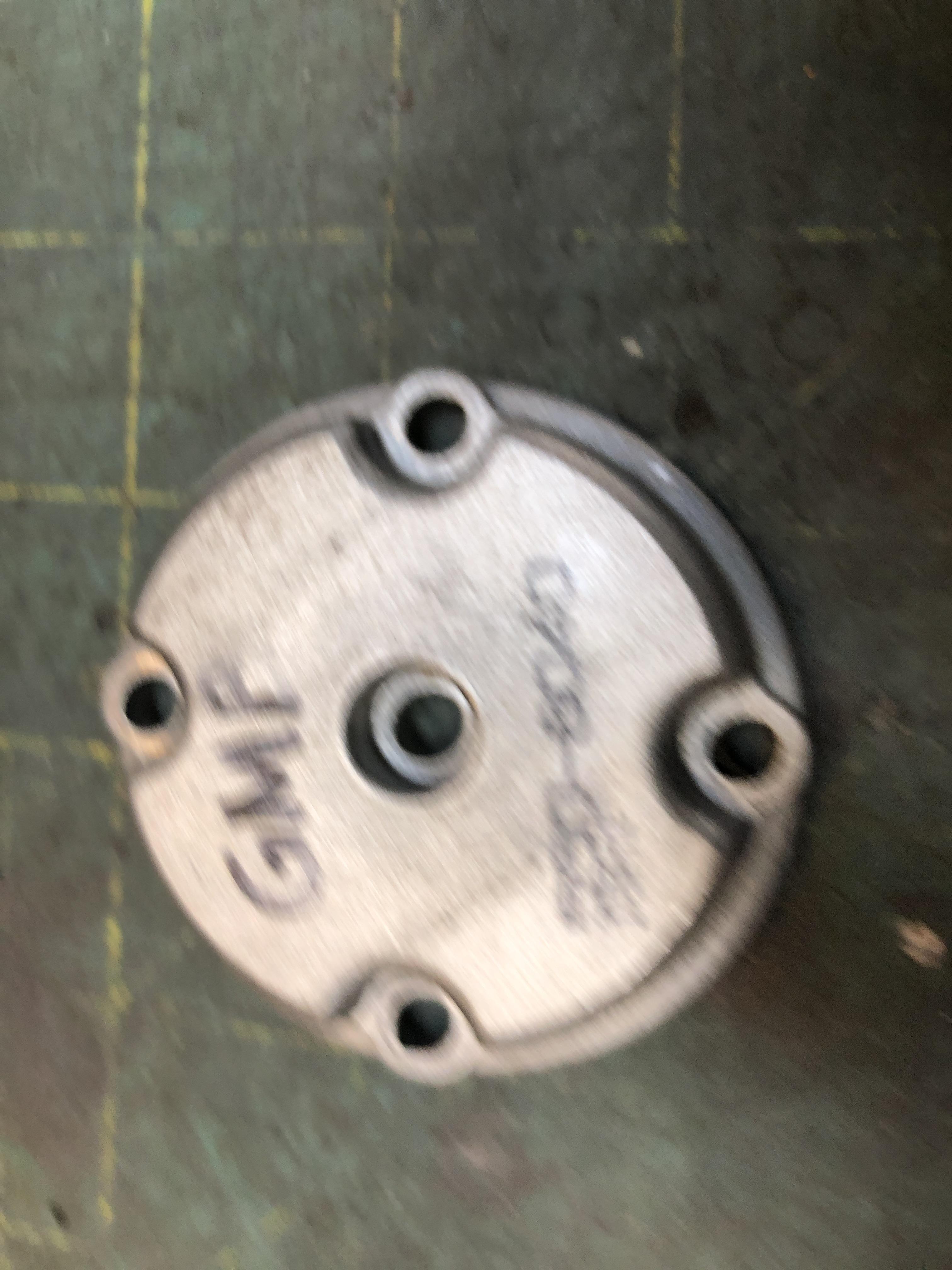
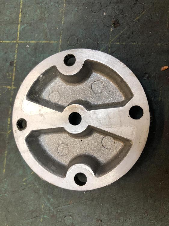
First thing to say about the "details" is that all the OEM pumps I took apart and scavenged parts from are identical as far as the location and size of the bolt circle that bolts the main body halves together and the top cap in place. So you can interchange just about any part with any part from any brand. The GMB and Spectra ALSO use the same bolt patterns. So you can interchange their bits with the OEM bits. There are small gotcha's here. Some of the upper caps are not interchangeable across all brands as the divider wall in the center is not in the same clocking with the bolt pattern. All you have to do is use a matching cover and middle housing from any one brand. Next is a small annoyance that the way the check valves are held into the middle housings is VERY different with the GMB/Spectra. Cheaper and crappier of course. They use a 4 point punch around the perimiter to trap the check valves into the housing. Hard to get them out, and if you did, you couldn't get your OEM check valves to stay in as you'd have a heck of a time re-punching around the edge to keep them tight and in place. Pictures coming. SO,. It actually makes sense to use the check valve housing and its matching cap from your old OEM pump and bolt it to the GMB/Spectra base housing. Keep all the good bits together. It does mean you have to do so sort of clean up of your OEM castings to match the new GMB castings if you care about that stuff
-
What you do, is go buy the $19 GMB, replace its check valves with your old perfectly good OEM ones, and put that hybrid baby back in the car for millions of additional miles and smiles. (Please put the GMB check valves on the cement floor and crush them into dust with a large hammer, lest you get tempted to use them at a later date. Don't) You get a new diaphragm, new lower seal, your perfectly good check valves, and the new GMB upper diaphragm that all make up a nearly new unit, and should run for a few years pump. Ok, all is not perfect here, there are a couple of details you need to deal with, but its all manageable. I'll explain in a but once I take some pictures. I guess the risk is that the GMB diaphragm material will fail faster than the OEM (or the new Nikki ones you get with Nikki pumps for non Z's to steal their internals from, remember that thread?) that is still to be seen, but all in all, maybe we have a cheaper route to rebuilt pumps here.
-
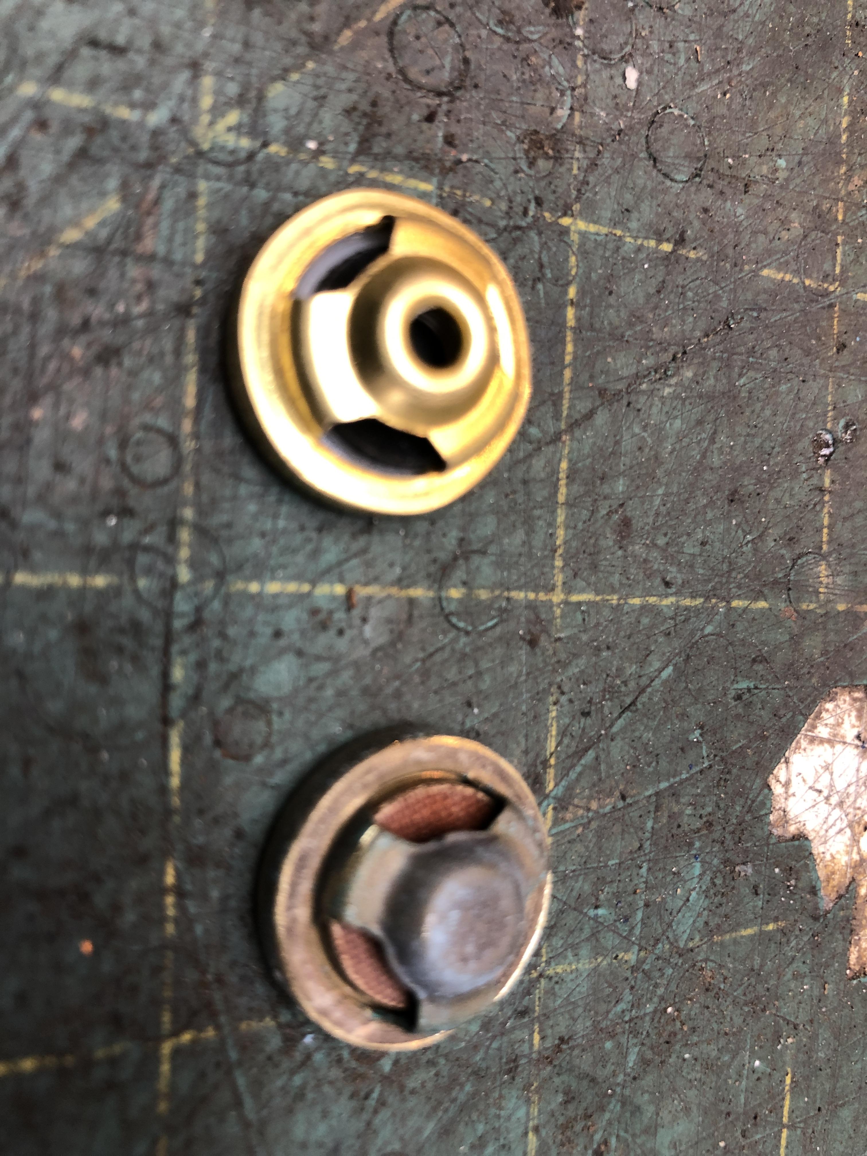
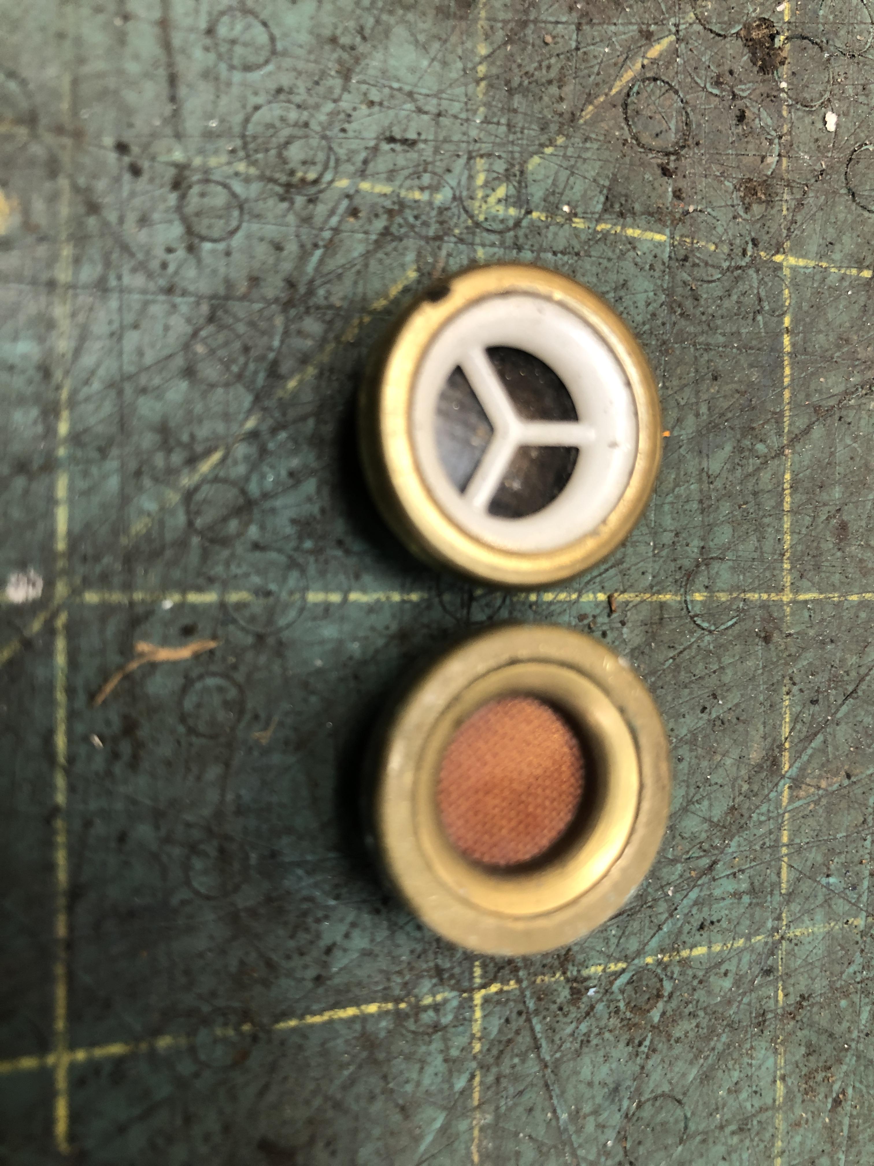
I've recently been through the wringer on mechanical fuel pumps. I LOVE the stock mechanical pumps and dearly wish to be able to use them more. Silent, plenty of volume to run triples etc up to 250 hp (my educated guess). Stock new pumps put out a CRAP load of volume even at cranking speeds. The cheap "offshore" GMB and Spectra fuel pumps that are out there that look like the stock Nikki/Ampco/Kyosan Densi pumps have been reported here and elsewhere are a ticket to very early failure. I can further attest to this experience. Had a fresh GMB make it about 10 km before leaving a customer/friend stranded. So after much investigation of the issue, I have good news. 1. The GMB and more expensive Spectra are identical inside. The diaphragm and check valves are visually and texturally identical. Might as well buy the GMB ($18.72 CAD on Rock Auto) 2. The problem is with the check valves. The design of the flapper is weak and shitty. The OEM diaphragms are thick and strong and seem fine. The failure is that they stop (or barely start ) being able to pull fuel from the tank. Any air gets in there and they loose prime. If you actuate the pump by hand on the bench in a vise with your finger over the intake, you can barely feel any suction. Do that with OEM pump and it will suck the skin off your finger tip. (Air intake only, no liquid). Now the really good news happens when you want to rebuild your old OEM Pump. Up till now it's been tough to find rebuild parts. I took apart about 20 OEM pumps (all three brands, 14 Z and 6 510 ) and noticed the following. 1. Diaphragms; Depending on age and use, some were fine, some were hard and/or cracked. No surprise. About 40/60 good/bad. 2. Upper diaphragm. Not even sure what the function is of the upper rubber diaphragm, but 100% were soft and reusable. Don't think they endure much hardship. Maybe one was a little stiffer than the others. I'm sure we could fill an long thread discussing what its for.... Please don't here. 3. Check Valves. The real surprise. 100% of them were 100% perfect and appeared nearly brand new. All were clean, no sign of crud buildup or damage or erosion/corrosion. These things are indestructible apparently and totally un-affected by fuel or time. 4. Lower seals. Where the rod passes through to the actuator. About 4 out of the 20 were still soft and usable. Lots of splits and hardness. Ok, knowing what we know about the new copies (GMB and Spectra) and the old faithfuls, and what's wrong and right about both species, is anyone seeing the possibilities here? OEM Body, check valves removed OEM check valves, front and back. Thick solid valve body. GMB check valves, front and back. Thin rubbery floppy material. GMB check valves are held in place with punched nibbins. Very hard to replace the valves. Well, easy to get out, but how do you keep new ones in? You'd have to drill and tap a pair of center holes to use the stock center hold down bracket thingy. Do-able, but.... Are these held in tightly against the gasket? Is there a gasket? Do they come loose with use and abuse? Inquiring minds need to know! GMB mid case with their check valves in place, top view back side of GMB upper hosing. Note different shape of center beam. Top of GMB pump housing. Fuzzy picture like the whole situation.


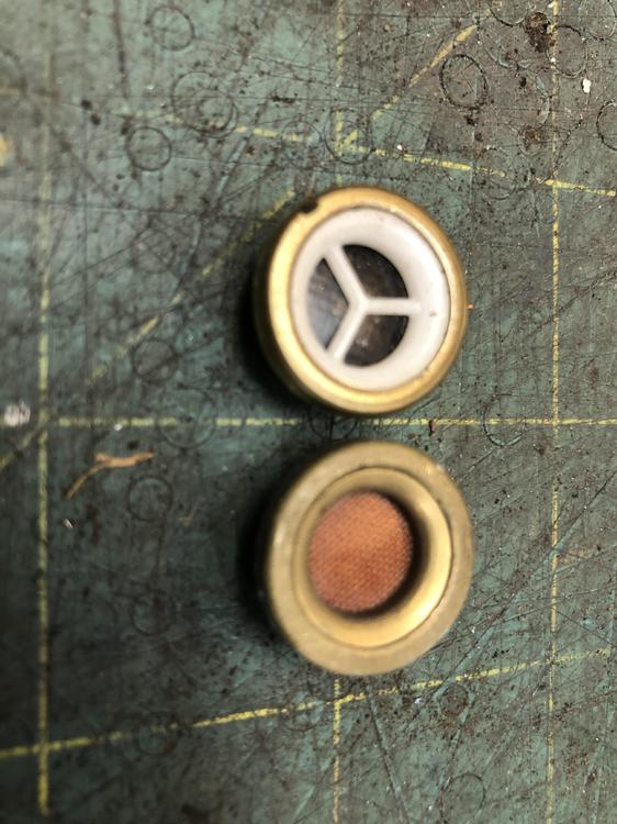


-
Pertronix is famous for burning up if you leave the Key in the ON position with the car not running for more than 15 minutes or so. Pertronix II is supposed to be more tolerant of that but I’ve seen failures.