zKars
 Subscriber
-
Joined
-
Last visited
Everything posted by zKars
-
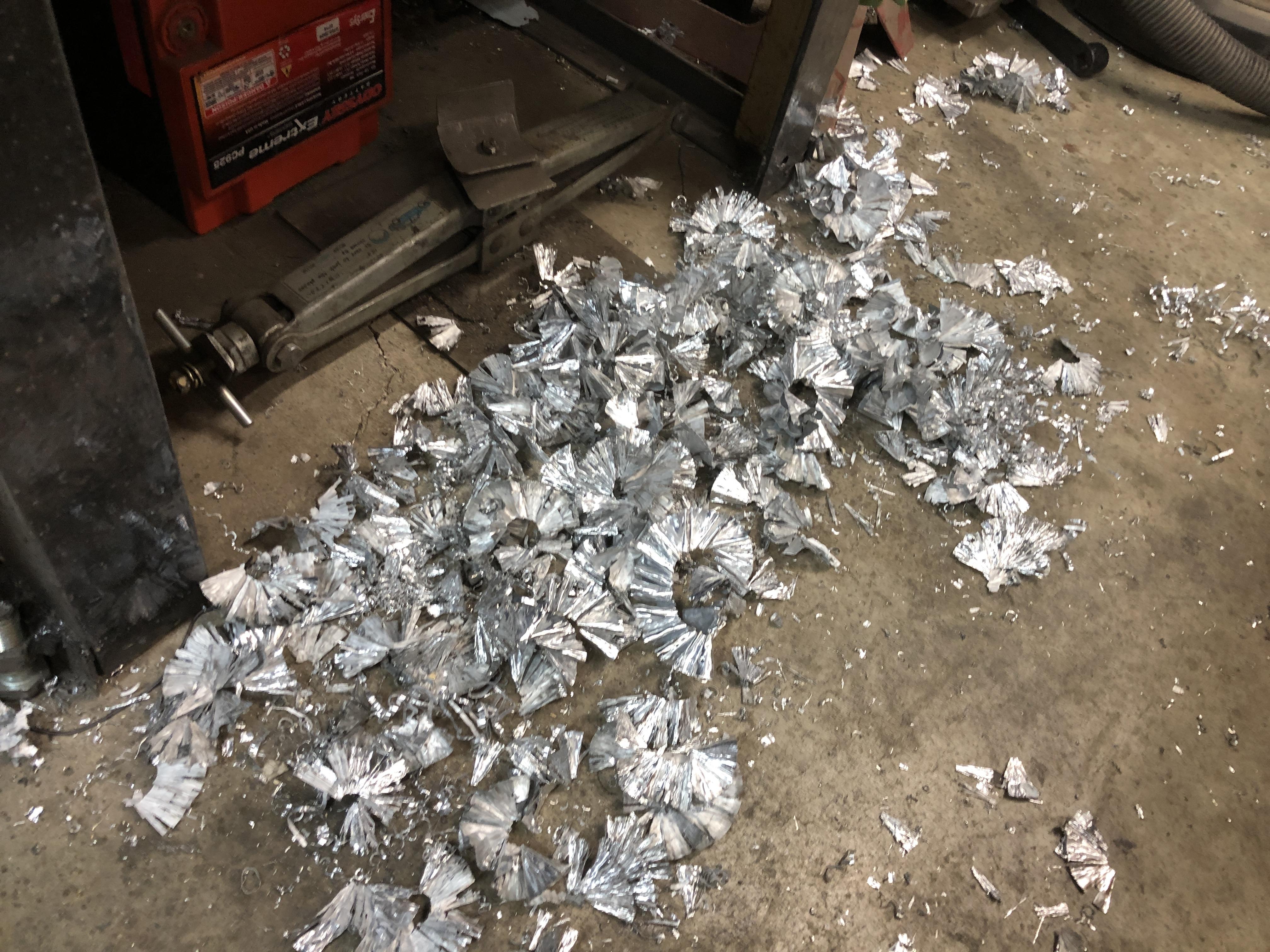
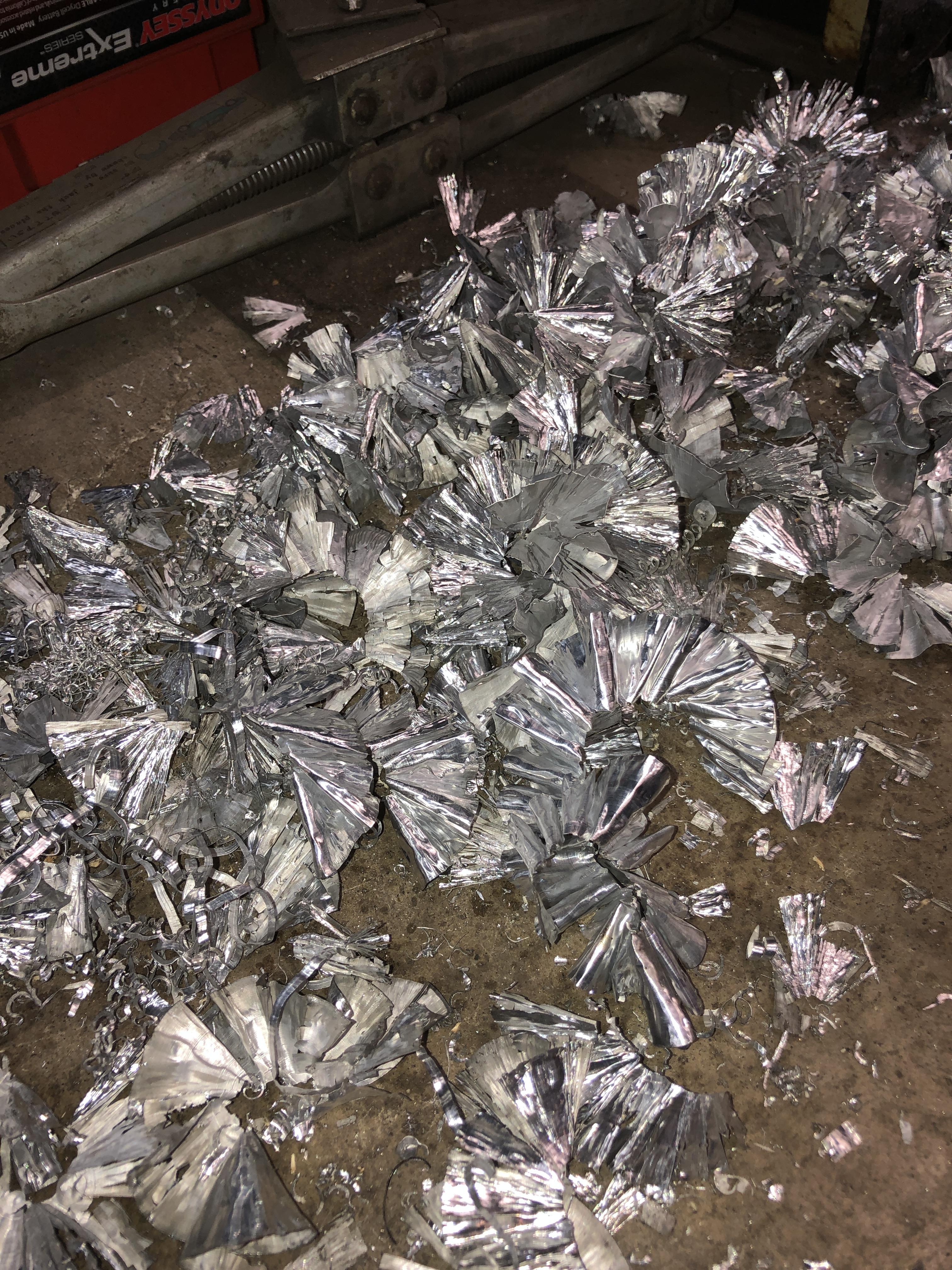
 And if anyone wants pretty tinsel for their Christmas decorations, let me know.

-
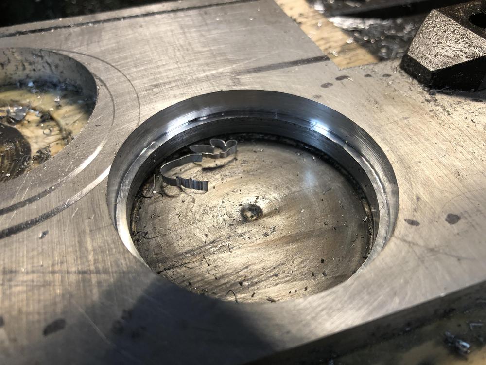
Been busy today proving I can drill, no actually enlarge a hole. I drilled a 2.25” hole in some 1/2” aluminum plate using my Forstner sawtooth bits, about 57mm, then adjusted my boring head until I got 62mm hole. Well, slightly smaller, actually trying to match exactly the hole in the C type bell housing I have. I’d rather be over so slightly small then enlarge with a bit of sanding to make perfect. The insert style bit can easily cut the 57 to 62mm in one pass. Once I get it perfect, I’ll spot weld the boring head and bar into the head for repeated use.
-
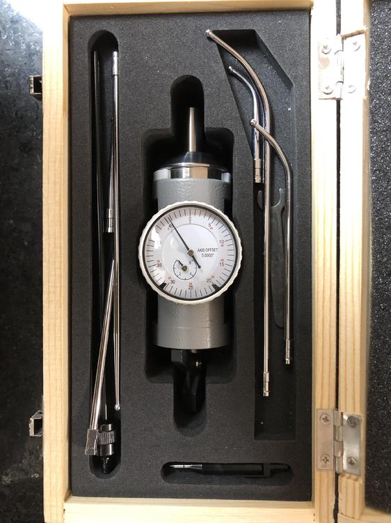
So today I go to play with my new co-ax center finding thingy after drilling a nice 2-7/16 hole in a 1/2" thick piece of aluminum plate.. Get the co-ax, chuck it in my arbor, attach an indicator arm, move the table around a bit, start to move the indicator arm a bit to see what the dial gauge is saying, and..... It doesn't work. The needle never so much as budges when you move the center shaft in and out..... There is a pin I'd have to punch out to disassemble, but figure that will end my ability to return it. Back in box to Amazon with a return slip. Got what I paid for again..... sigh..... Order a better one and wait for tomorrow to see if the quality gods are on side or not
-
Do NOT try to Google “Tranny Doctor”...

-
And for the Cap’t, ...
-
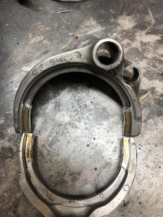
Ok I have five transmissions apart in the shop. A 4 speed, Three 71B’S and a 71C. This is getting out of hand. But I’m learnin’ lots. Best of all is that the 3-4 shift fork from the C is perfect match to replace my bad 1-2 shift fork in the B!!!!! Only the 3-4 C shaft is 16mm in the C, the others are 14, so don’t even need a bushing. The only thing you have to do is make roll pin hole in the B’s shift rod bigger to match the larger hole in the C fork. Now regarding the new fork mentioned above from transdistparts above, it likely will not work. The 1-2 shift selector C type is slightly larger than the 3-4, so the fork is too big. They aren’t listing a 3-4 fork replacement.
-
Looking for trans parts? These guys have a decent selection. Even claim to have my shift fork. https://www.transmissionpartsdistributors.com/fs5w71-fs5w71a-fs5w71c-fs5w71e-fs5w71g-fs5w71h/ Thanks to Aaron Heath on FB for pointing this out. I put out a plea for parts last night.
-
I knew I could count on you guys. Of course! The boring head. And a coax? Looks complicated, but you need what you need, right? off to the tooling store! Yahoo! all this requires that my mill head fits down into the transmission case. Haven’t tried that yet....
-
I looked. PM me so Santa can do his thing


-
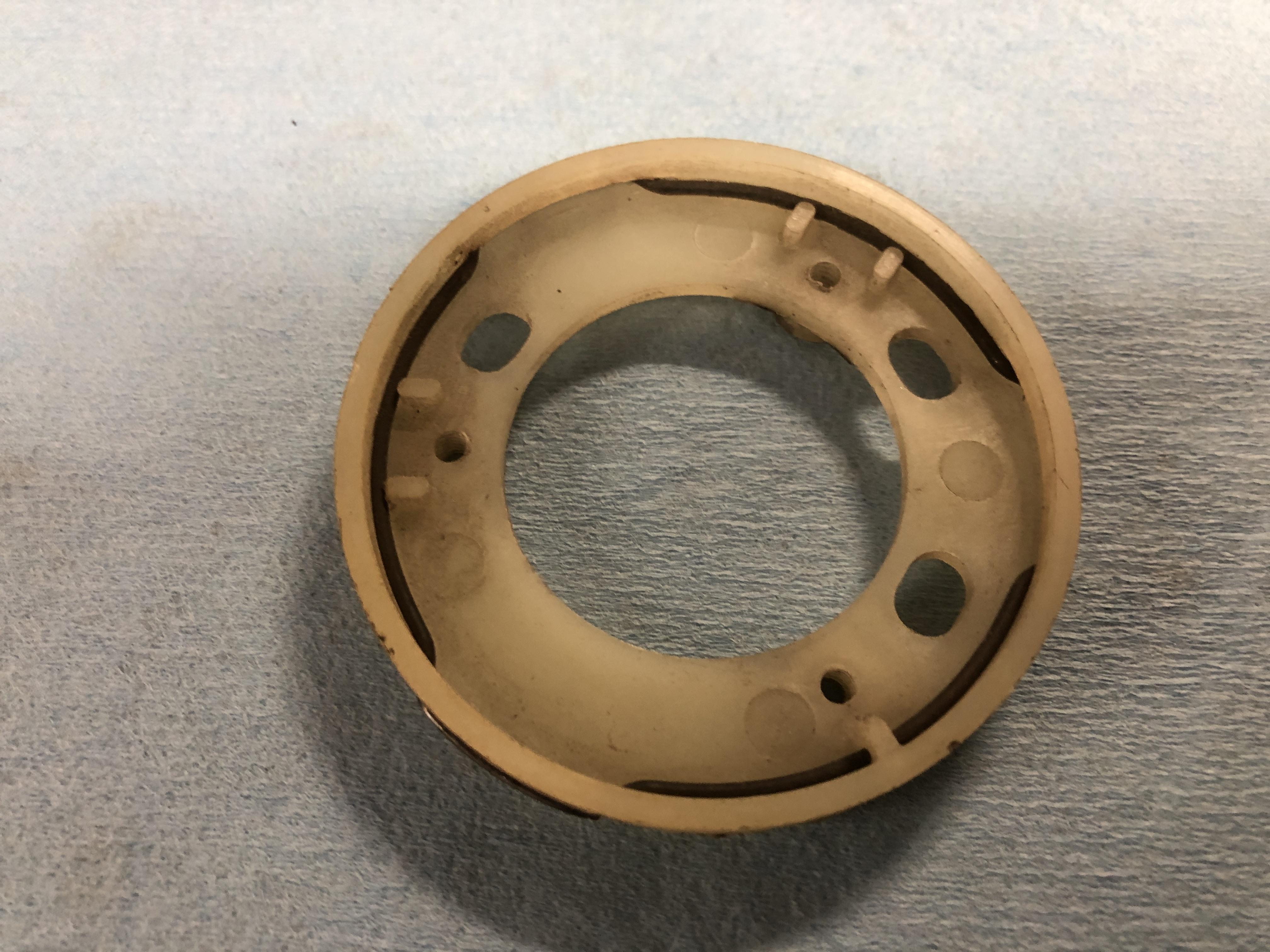
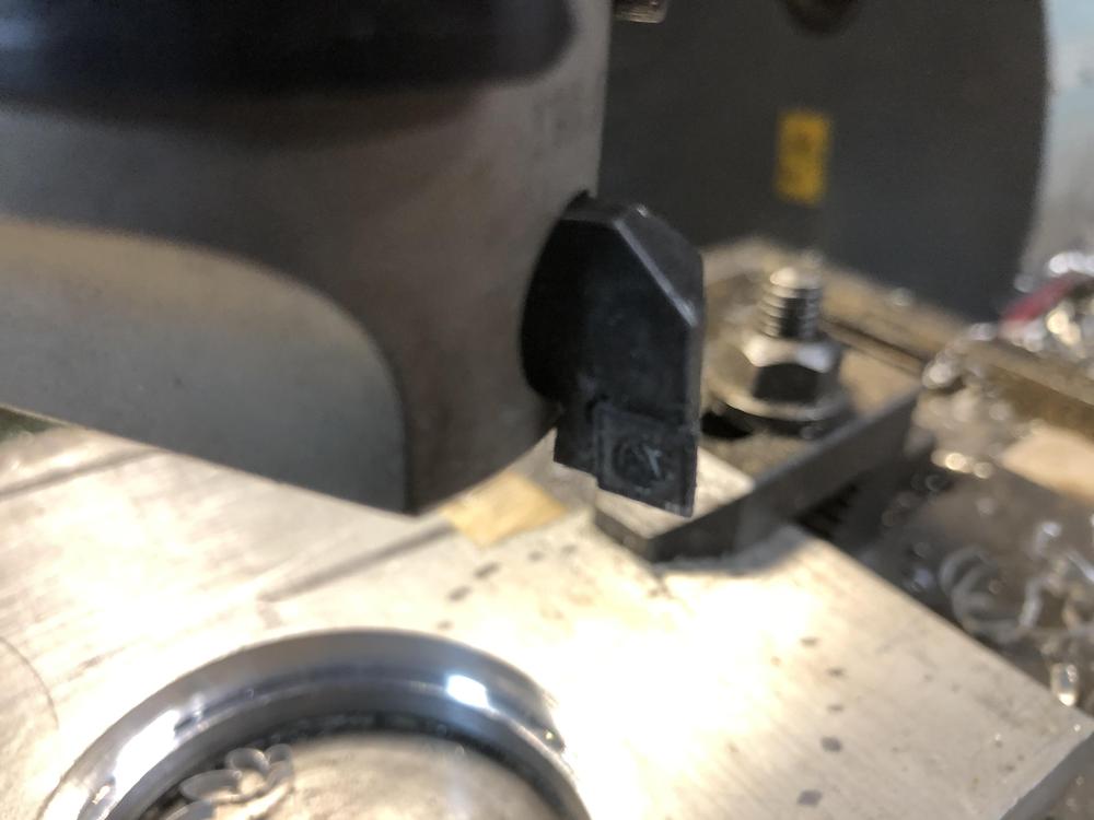
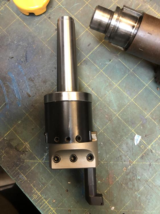
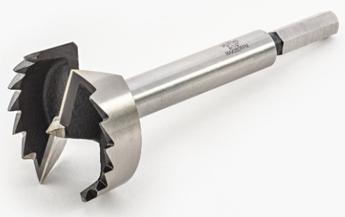
So all you machinist's tool makers, inventors or dreamers out there. If you were going to "create" a 62mm cutter of some sort to put in your mill to enlarge a 56 mm hole, what would it look like? PS. 62 mm is just a teeny bit bigger than 2-7/16" (61.92mm) and just a tad smaller than 2.5"... (63.2mm) I've drilled a LOT of holes in Aluminum with one of these. They make a lovely hole with lube and a gentle hand. Buy a 2-1/2" one (63.2mm) and machine it down to 62mm, or a 2-7/16" one and weld on / add a cutter ?? That nice round shaft on there is exactly 0.500" to fit in a nice collet chuck. Centering is simple. I'll lathe up a 56mm puck with a 0.500 hole in the middle that fits oh so nice and tight in the bearing hole, then use a 0.500 rod in my 0.500 collet chuck to get the mill head in the right spot. Then put the bit you-all are designing for me in collet and cut away! Simple right?
-
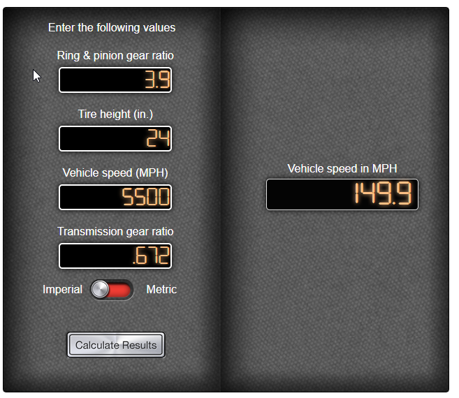
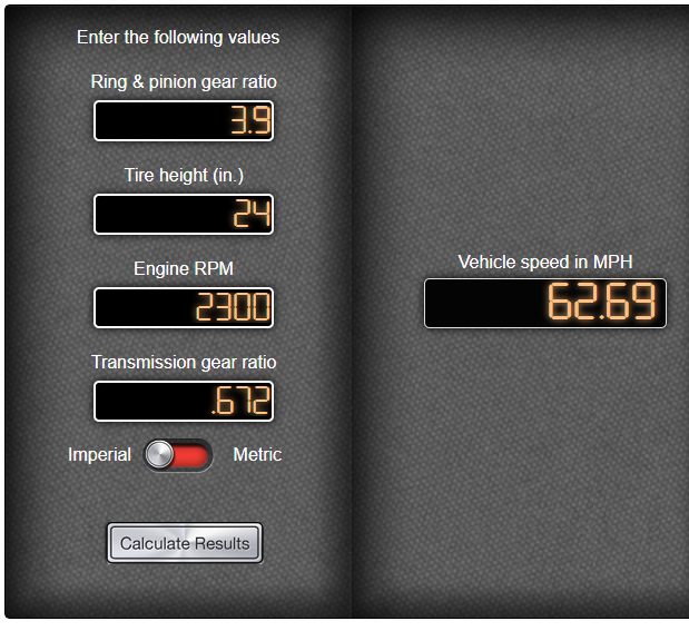
I have closer to 24 in tires Would be fun to get my little yellow brick to go 150! My WAG about 2300 at 62 mph/100 kph is pretty close!
-
https://www.jbugs.com/category/vw-hoses.html
-
Feel is such a personal thing, and torque curves and rpm ranges are different in every car. As are driving styles and how I drive 90% of the time. I will have to put it in and try it out to see if I really like it. Swapping trannies is a just nice way to spend an afternoon. I plan on several long trips in the next couple of years so I hope to make good use of that .65 OD. Got the torque to lope along happy at 2300 at 65 MPH. I’ll be running 3.9 subie CLSD currently working on an idea for a jig to make the 62mm bearing opening enlargement easy and relatively fool proof.
-
-
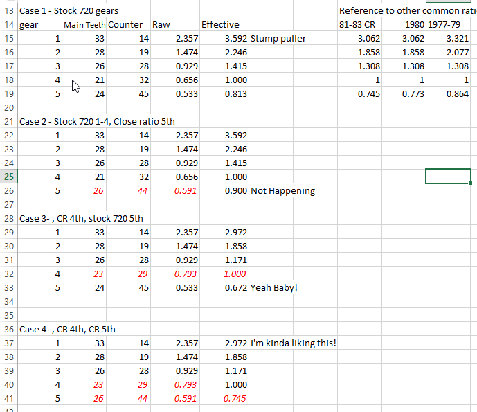
The more I stare at these ratio's the more I want to try case 3! Case 4 is also a winner if you like the .745 OD and gives you much more reasonable 1st over the stump puller truck ratio
-
Alas, I am but a dreaming fool. My plan above to use my .754 gear set will actually make the 5th ratio a stupid 0.900. You have to account for the 4th gear main/counter gear ratio to correct the actual 1, 2, 3 and 5th gear tooth count ratio's to get the total drive ratio. With the close ratio, the 4th gear teeth are 23 vs 29 or 0.793 ratio, then apply that to that actual 5 gear tooth ratio, which are 26 and 44 = 0.593, / 0.793 = 0.745 actual 5th drive ratio. But do that with the truck 5 speed gears, 4th main and counter are 26 and 44, or 0.591. so with my 5 gear stuff. is 0.593 / .591 and you get a utterly heart breaking 0.90 5th ratio. Not doing that! But!!!!! As I'm typing I'm thinking more (haven't learned my lesson yet...), I could ALSO use the 4 main and counter gears from the close ratio in the truck trans (the only gear you can remove and replace on the counter shaft hahahah), which would give me the 0.745 5th, but wait, oh crap, it will also screw up all the other 1st and 2nd and 3rd ratio's as they are corrected by the 4 main/counter ratio. Let's see how bad is that.... So I have two sets of 5th gear gears, and two sets of 4th gear gears, so could build 4 different ratio sets. Let's be scientific and get Excel going. One of these combo's "might" be worth trying. 720_trans_ratio.xlsx
-
Back on topic Way in the back of the tranny garden (forest?) I remembered I have a 720 truck five speed! I've been ignoring it because it has a bell housing I can't use on a Z or 510, anything with a tilted L series. Outwardly it looks identical to any long eared one-muffler hanger FS5W71B except for a couple of key details. The wrong bell housing for one, and the fill plug is on the other side of the case. Look here to review the differences if you're not on top of that. https://ratsun.net/topic/74205-620-transmission-identification/ BUT this sad little truck trans IS a donor for my worn out 1/2 shift fork! They are identickle! Took it apart today, and it's in perfect shape. Gear ratio's are interesting. Being a truck, first is a bit of a stump puller. 1 3.592 2 2.246 3 1.415 4 1 5 0.813 Let me say here that I am actually not a fan of the much coveted "close ratio" 5 speeds. Gotta say I've had just about enough of the fawning and slobbering over their supposed greatness. The 2-3-4 ratios are nice and close, wonderful for road racing I suppose, but first is about 2.5 miles away from 2nd. I've always been a bit ticked about the huge gap between 1 and 2 in both my Z and now my 510. Not ideal at all for tight auto cross circuits. SO!!!! I going to hypothesize that I like the above truck ratios for 1-4. Now the Z close ratio 5 has that nice .745 overdrive, while the truck has a so-so .813, but I have a solution. I'm going to put the lovely .745 5th gear gear bits from my Z trans into the back side of this nice truck cluster. It's all separate gears behind the intermediate plate, just gotta take ALL the parts from one and stuff them in the other. BWAHAHAHAHAHA!!! THEN when I break it next I'll stuff the C type in there and live with it's ratio's. You know, a guy could get the bell housing machined for the 62 mm front counter shaft bearing, and strengthen up a B type pretty nice. It's the bearings that give out, never busted a fork or gear set. Who needs those fancy C types with their longer length, wider gears and skinny syncro's anyway? ( read that with a sneer pls).
-
If its failing that quickly it is likely a defect in the driveshaft surface that rides on the seal. You have four options 1 replace the seal again, but don’t put in in as far as last time. Ie put the seal lip at a different point on the driveshaft surface. 2. use a speedi-sleeve. Google it. 3. replace the driveshaft yoke so you get a fresh seal surface 4 polish the driveshaft sleeve to remove the defect.
-
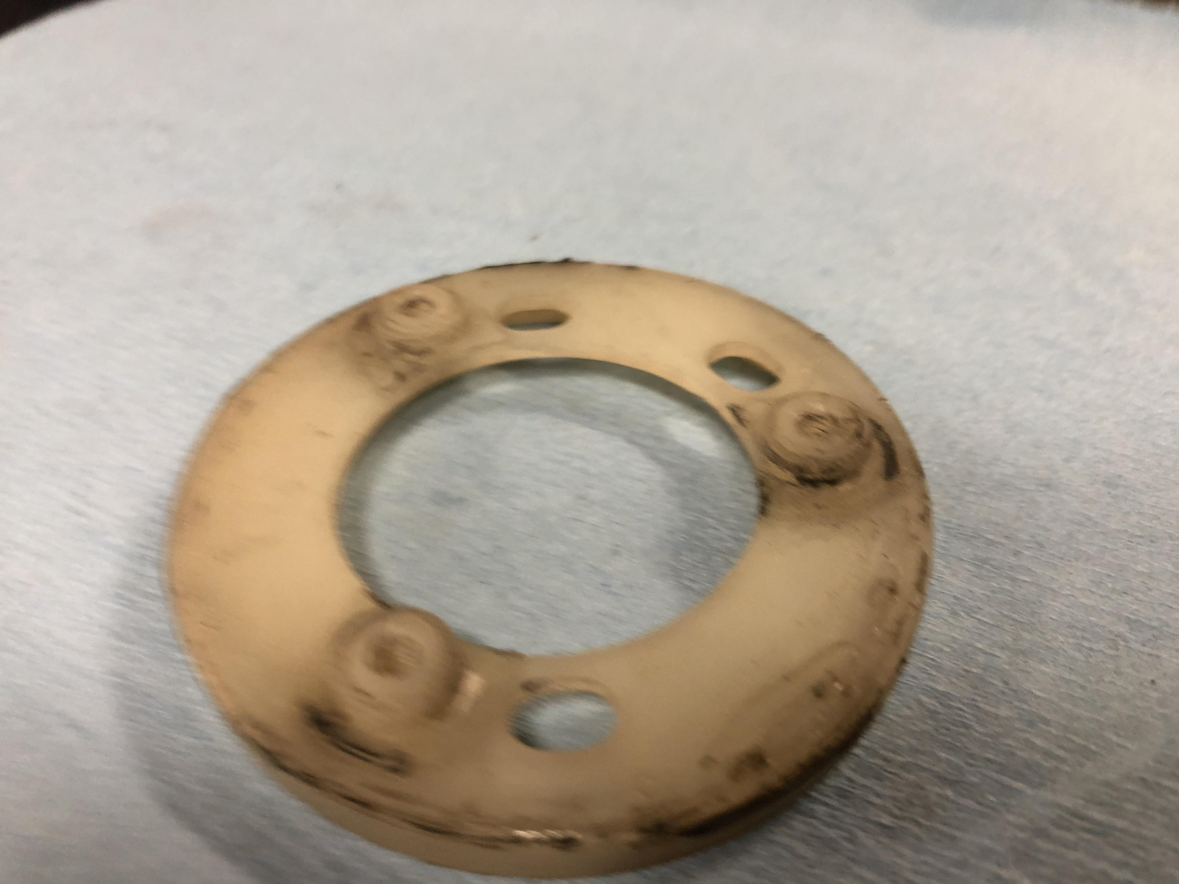
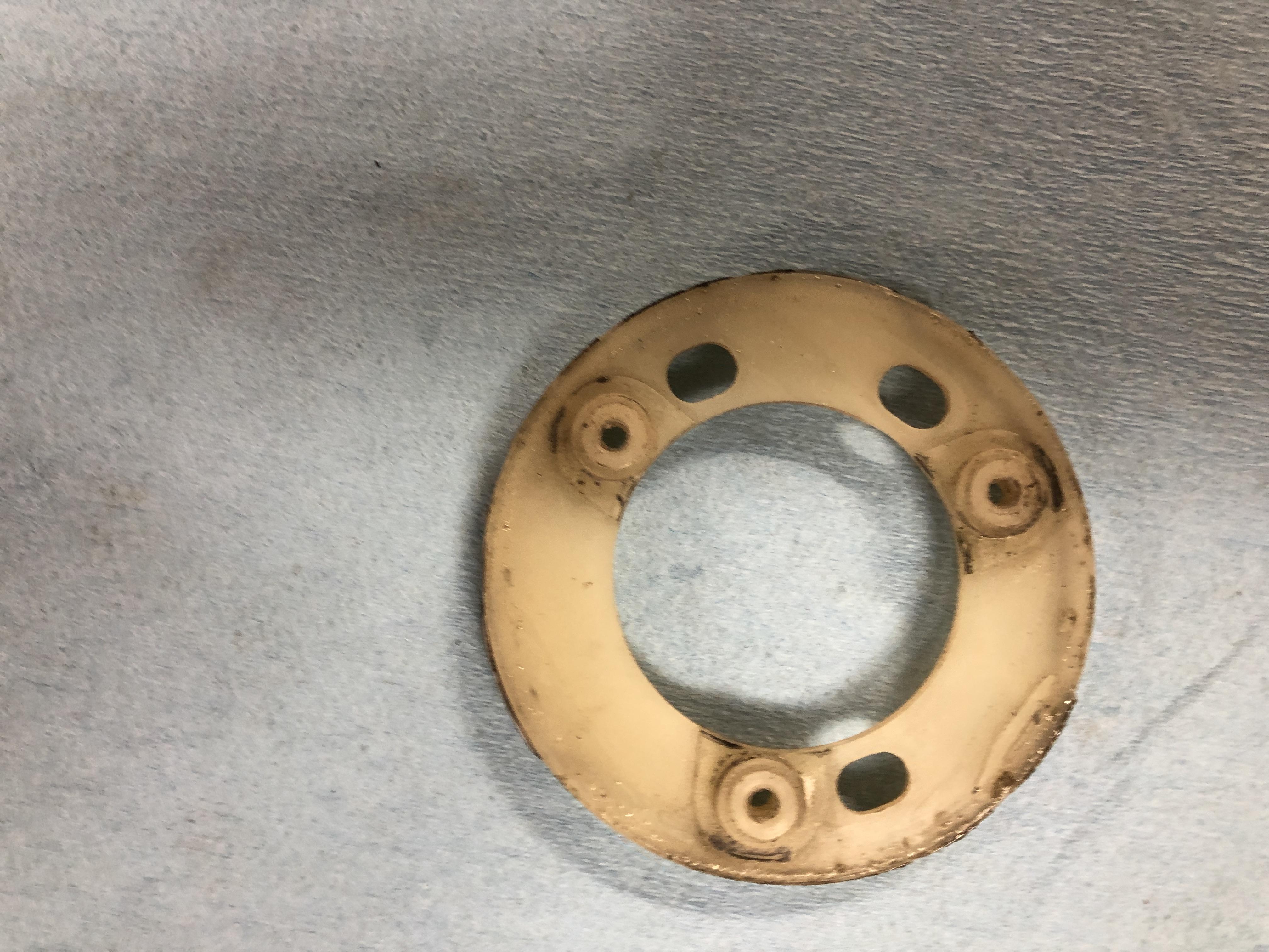
This is indeed a problem. The Nissan alloy mags use a special nut as shown above and rely on a tight fit for wheel centering. The shank diameter is not easily available in aftermarket lug nuts of this type, they are all smaller. The Nissan part number is 40224-R4670 and they are over $6USD each! Fortunately Dorman makes a replacement that is more reasonably priced. https://www.rockauto.com/en/moreinfo.php?pk=1848480&jsn=531 DORMAN 611241 Just a note on the amount of run-out I had that caused wheel shimmy. 0.050 on one and 0.030 on the other front. Measured on the side of the rim as the wheel was turned by hand.
-
-
I'd suggest a run out check on the rims. Just put a dial guage on them and spin them and see how out-of-flat they are. I induced this problem with small cheap wheel spacers that were anything but flat. See the linked thread.
-
I have some used ones and a set of new reproductions if you can’t find any closer to you.
-
I found a picture of the hazard switch in HLS30 -03798, a 5/70 car. Double triangle.
-
Excellent advise Dave. When I read the descriptions of all the different gasket makers, adhesives, sealants etc, I find it all highly confusing. Just go read about these products on Permatex website. I guarantee you will be confused on what to use in what situation. Sealants can be gasket makers and sealants. Gasket makers don't seem to be great sealants. My favorite example is when I look at the gasket making products, and come across the category for Anaerobic gasket makers and sealants!!!! Even they can't keep the two apart. ANd then there is whole section on "Gasket Sealants". https://www.permatex.com/product-category/gasketing/gasket-sealants/ Arghhhhhh!!!! No wait. This stuff Permatex® High Tack™ Spray-A-Gasket™ Sealant, is actually an adhesive! It's for sticking gaskets on metal surfaces. Dear lord..... All I want is no leaks and to use fewer paper gaskets. Reading this tonight, it does clear up some of the areas that I have never seen clarified properly about proper use of sealants and gasket makers. Give it a read. Especially RTV gasket makers vs Anaerobic flange sealants. At least it makes it clear how to use each one properly. https://www.permatex.com/ten-common-gasketing-mistakes/ Oh, and the "right stuff" seems like magic.
-
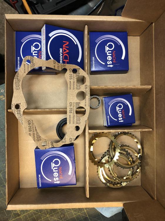
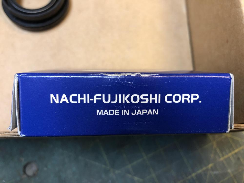
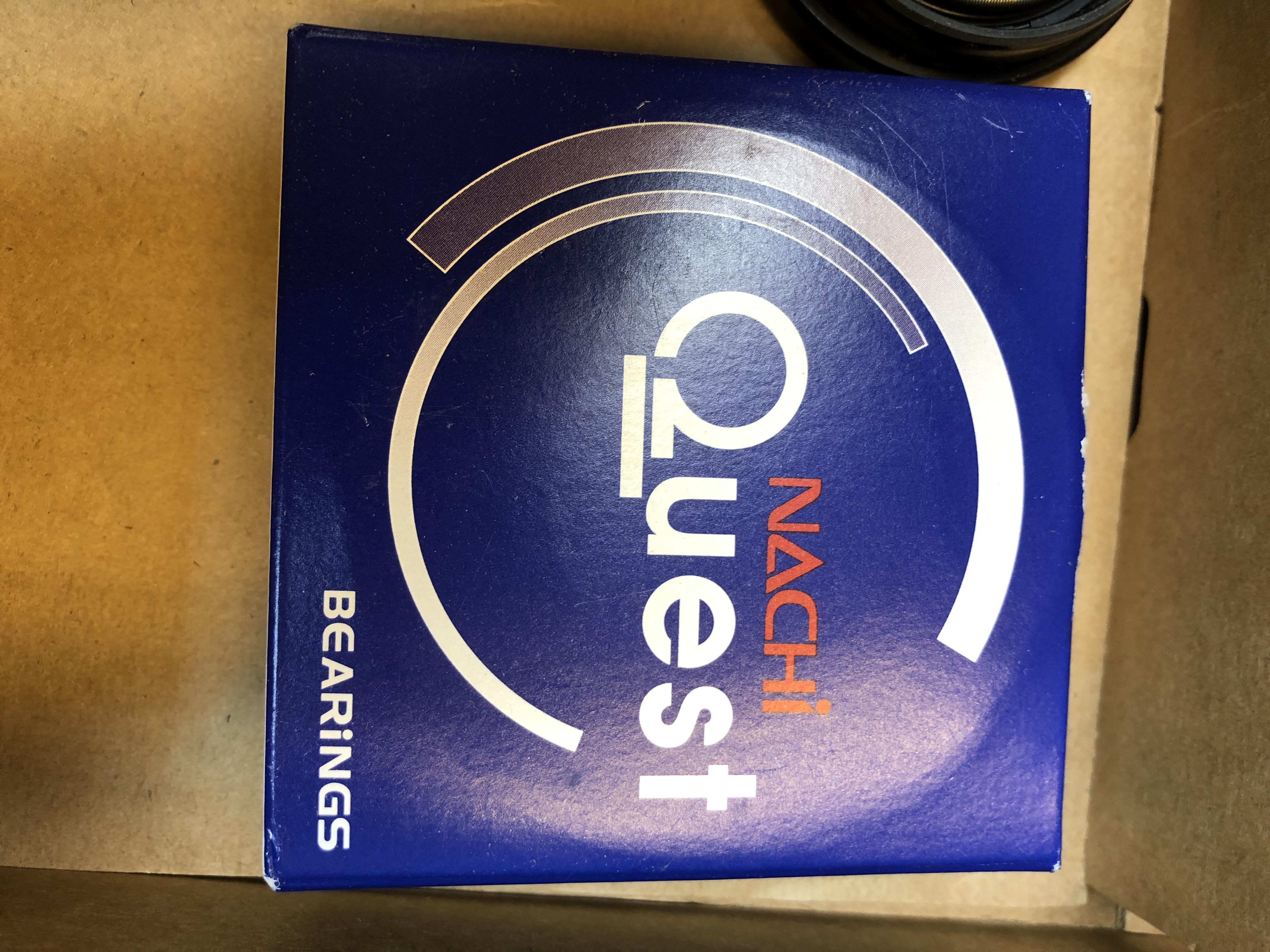
Ok, pics of what I got from drivetrain.com, kit BK104WS Nicely organize, everything is there, and best of all, the bearings at least claim to be of Japanese origin! you only get the one needle bearing. It is for either the 5 gear or where the front cluster attaches to the main shaft. It's construction is definitely "different" than the originals, or the ones I got from Nissan. Doesn't mean its worse but the cage is definitely more coarse looking.