zKars
 Subscriber
-
Posts
3,742 -
Joined
-
Last visited
-
Days Won
107
Content Type
Profiles
Knowledge Base
Zcar Wiki
Forums
Gallery
Events
Downloads
Store
Blogs
Collections
Classifieds
Everything posted by zKars
-
Well I got the MSD 8214 center contact. $15 canuck bucks. Nice piece, but about 2x larger diameter than the mini center in the Bosch cap. Its not clear, but it appears to be not solid, so its not going to be practical to machine it down to size. Pretty tiny, my lathe is not.... So now its a balance of how much $$ and time to design/make verses buying a few stock caps. The one we found in Port Alberni came with a $50 price tag. Ouch. Rockauto are $25ish, but with shipping for me...
-
You betcha. On the way over this afternoon. Thanks
-
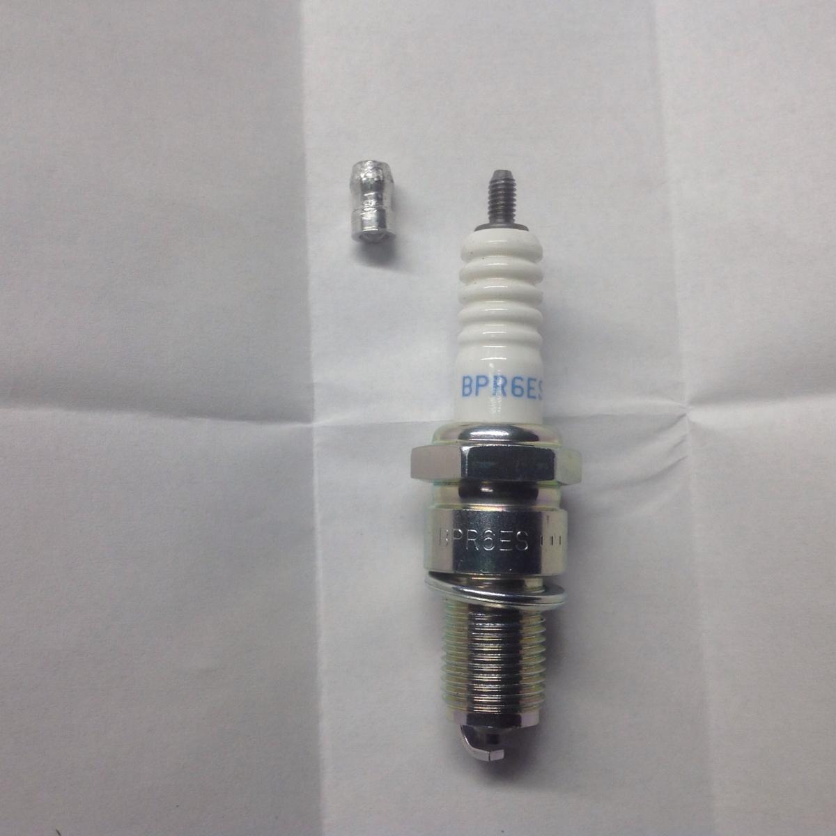
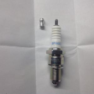
So I've been chasing ignition problems lately (see my post re 123IgnitionUSA dizzy and melted cap center button), so I've been going over my total spark system looking for problems. I (re)-discovered one issue with the plugs. Years ago I had a persistent misfire and finally started swapping out plugs one at a time until I found the culprit. You may not be aware that the tip of these plugs is threaded on. That tip screws right off. There was one plug with a VERY loose cap. Threaded it back on tight, misfire went away. Magic. I remembered this last night, so I checked my 6 last night, EVERY ONE was loose from just a little to 1/2 to 3/4 of a turn! Every time you take the plug wires off (something some of use do more than others...), you give that tip a bit of torque I guess, and eventually.... I tightened up the tips, fired it up, and guess what. The smoothest idle I've had in a LONG TIME... The car ran 'ok' prior to this. Tons of power, just that nagging feeling that it wasn't as smooth as it could be. My AFR gauge used to jump around more than I thought was normal. Under static cruise, you'd swear there was a transient misfire going on. No more. Touch key, car starts, idles nice. Funny how a healthy ignition system makes you car run better. Big surprise... Go check your plug caps. Tighten down with a vise grip. Don't bust the insulator, just snug it up. No don't use locktight. Non-conductive.
-
You were in Tofino?!?!?! We were there 14-17th, Stayed at Middle Beach. Been going there for years. Love the drive, but the place is getting too popular, too much traffic! We had 4 Z's of various years out and one sad guy in a STI.... Could be worse.... Very good info on the button fagility with higher voltage systems. At one point I was using a brass crimp bullet connector to attempt a reconstruction of the button. Was working for a while, but the contact with the top of the rotor wasn't smooth, and it was digging in.... I'll see if we can adapt that MSD button to the Bosch coil. Wish we had Lordco in Alberta.
-
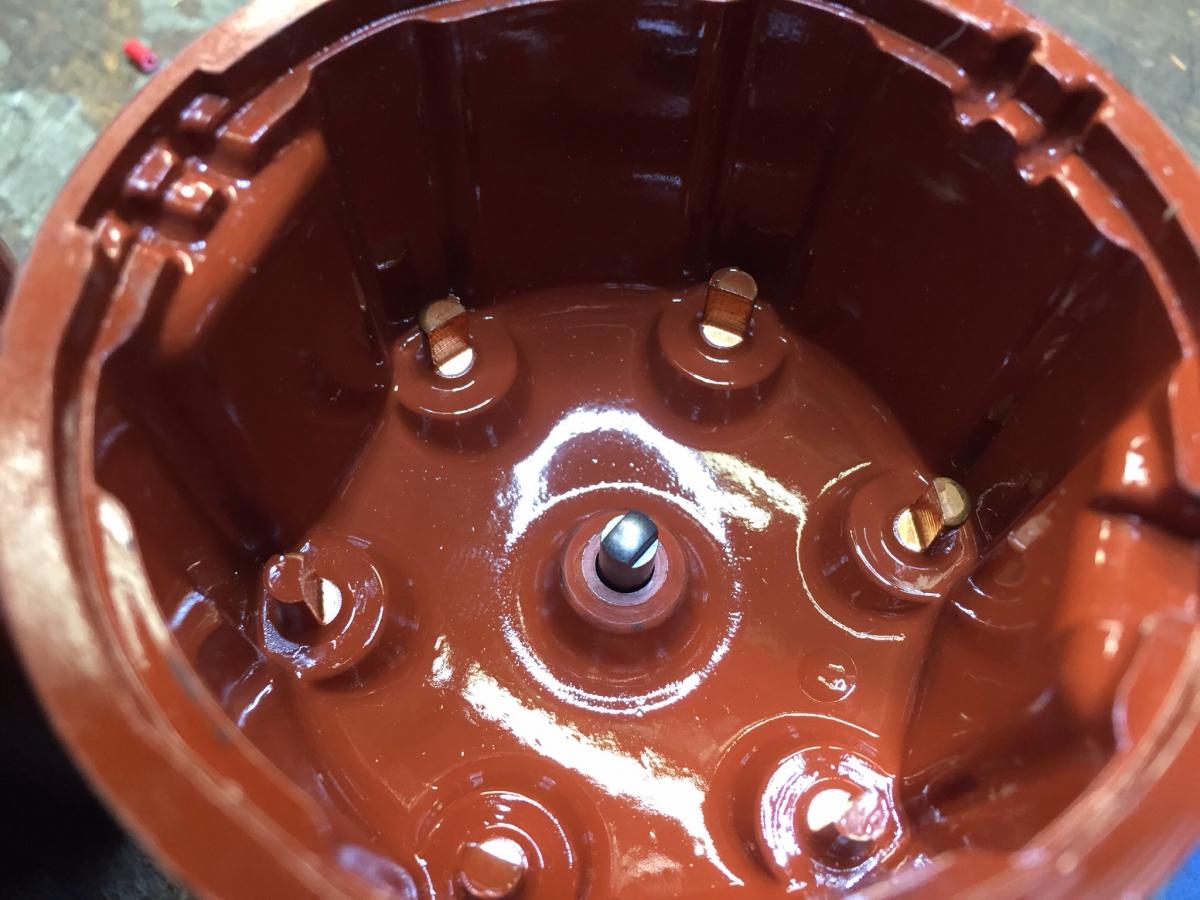
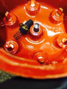
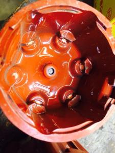
Have some feedback after another road trip with a BIG problem. We are at something like 20,000 km now, and had a problem with the distributor cap. The center carbon contact inside the cap is gone/worn right off. Old in first, replacement cap next. Contact tip is nearly 1/4 inch long The problem manifested itself as worsening and then very hard hot hard start. Discovered the coil spark was weak and initially replaced the coil as likely culprit. Eventually as things went from bad to worse, discovered the worn out cap center contact. No blame here, no idea why this cap should be worn out at 20K km, but I didn't expect that at this early age. Everyone check your caps! Replacement is any 6 cylinder late 60/early 70 german like Porsche, BMW or Mercedes. Bosch 03014 is one option. They also list parts here: http://www.123ignitionusa.com/four-4-and-six-6-cylinder.html More details about what transpired as trouble shooting progressed. As we were on a road trip, I had a spare coil, but it was only a 0.8 ohm primary type, 123 clearly specs a nothing less then a 1 ohm coil with clear warmings about reduced life if not, but that's what we had so used it. Started better, but after 400 km, found a MSD coil with a ballast resistor and installed that. Started ok, so carried on. After 1500 km (away from home in remote location, Tofino BC), and three days of rest, went to restart and it did initially then died after 5 min warm up. No restart. No spark. This is when the bad cap was discovered. A new cap was miraculouly found in Port Alberni (thanks Ed for parts ID by helping my friend Pat who went on a parts hunt). Unfortunately the new cap did not fix the problem. The car started but after warmup, ignition went to intermittent on/off status rendering the car undrivable. This indicated a problem with the dizzy internals. Not good. Forntunately I travel with spare parts and had an old E12-80 ZX dizzy to swap in. That got me home without further incident. Seems my short term low ohm coil use, bad cap, and eventual maybe not quite enough ohm total ballast resistor, and the related "temporary" wiring did in the 123 dizzy. Beware all yee who dare run non-3 ohm coils. I'll report back after the dizzy issue is fully diagnosed by putting it back in at home with proper wiring and doing some hot testing to see if it will fail now. If so, then back to 123 for service I guess. I'm sure Ed will take care of it and let us know what the problem was and how to prevent it in future.

-
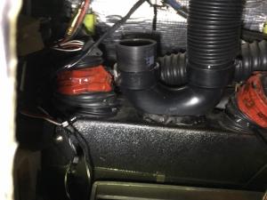
If you are not going to use the heater part of the GenII system then you can just use the heater hose holes to pass the AC hoses. Well, maybe and maybe not. A great deal depends on the routing of the hoses on the INSIDE and how they have to get from the firewall to the connections on the evaporator box. The stock heater hose holes are right behind the evap unit fan after its mounted, so you would have to run pre-bent hard lines to make an immediate 90 deg down. Each of the various plumbing options that Vintage Air has (rubber hose, hard lines, SS braided and others) will require different routing based on the how tight the hoses can be bent and how you need to get each connection from place to place. Cost also factors in, the SS lines are twice as expensive as the basic rubber stuff for example. The "correct" way to do this is to mount all the components, THEN route the hoses between them. Unfortunately the stock heater hose holes are not in the best location....
-
There is a way to scan and create a PDF document that is not expensive for an everyday Joe. Most multifunction printers that scan/print/fax can scan pages and make PDF files of them. Once you have your ~1500 individual pdf files, they can be pretty easily assembled in a single PDF. I can help with that if anyone needs such a tool. The tough and tedious part is separating the book, then feeding the pages one at a time to do the scan. Not much fun, but doable.
-
 Ok.... Sorry jalex....

-
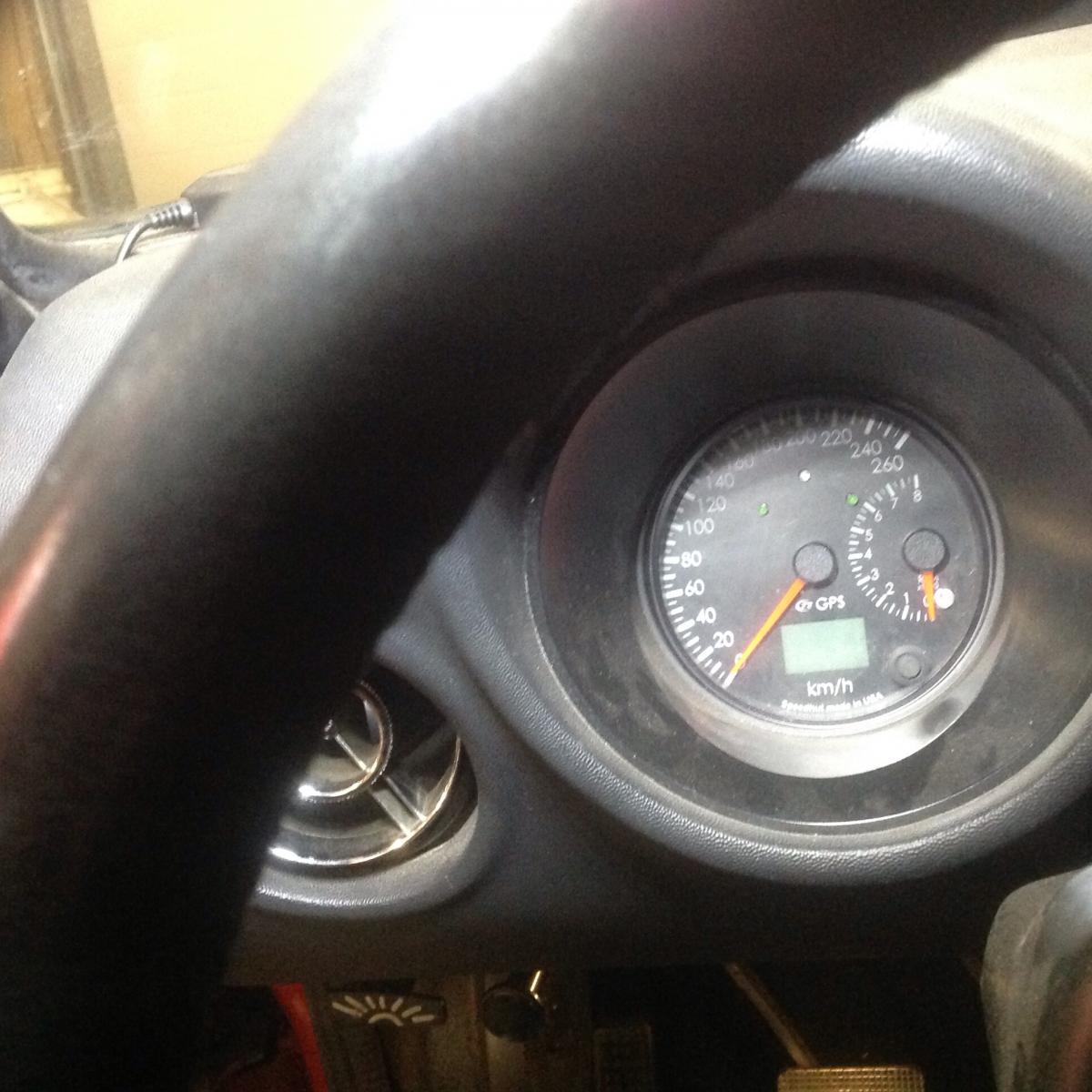
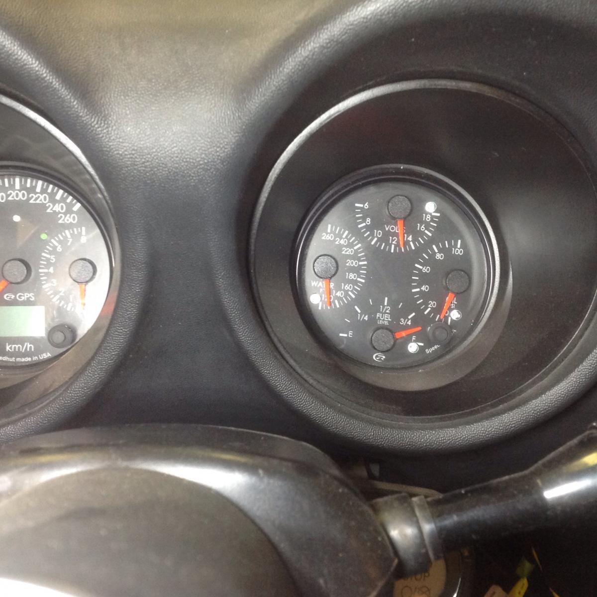
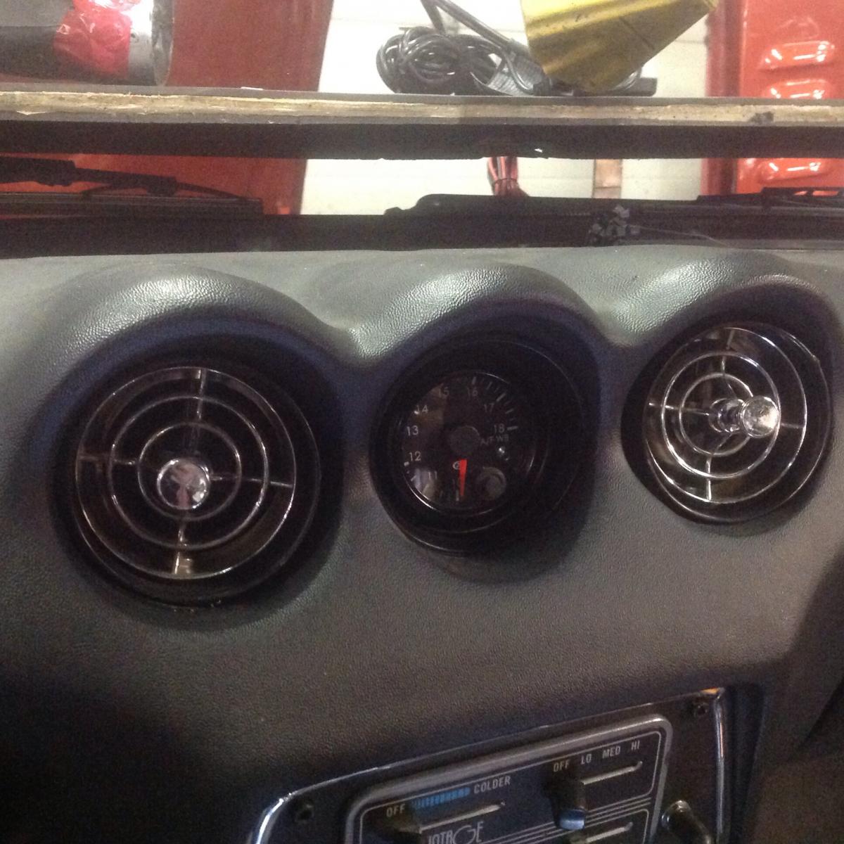
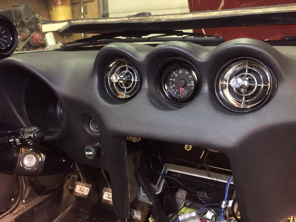
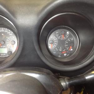
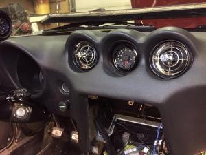
The eye balls on the end are definitely in use. The GenII has 3 outlets, so the outside two go to the ends with the eyeballs. The gauge relocation thing is tough for most to do without serious mods. I have speedhut gauges, so I have all the primary functions in the old speedo (Speedo-tach combo) and Tach (Fuel-oil-water-volts quad). I have AFR in the remaining center hole. Should probably have some fancy clock in there to look all modern and stuff... The center HCP panel is now a blank canvas. It needs the HVAC controls, and a spot for a nice stereo, and few switches to run things. That's all fodder for another thread. Back to the man's thread now please!
-
Perhaps I will take this opportunity to blow your mind on what the "right way" to use the Gen II system huge cold air output might look like! and how those two eyeballs get air from the center Gen II outlet. Somehow I think this is some kind of trap...
-
There is no room under the dash to have both the original "heater box" and the Gen II mini. Either or. I'm assuming you mean "heater box" both the box that contains the heater core (dash center) and the fan/blower assembly on the right side of that. You could, just saying, "could", use the stock fan/blower in place of the fan that comes with the GenII system. You would need to come up with some simple ducting between them. The GenII evap box would have to be slightly offset toward the driver. But the stock heater box and its ducting to the defroster outlets are lost. BTW, the GenII stuff hides almost completely. You do see the bottom of the fan on the passenger side of course, but it cannot be hidden completely.
-
Z's don't have a good place to put a control pod like that underdash. I certainly would not try to attached it to foam dash material. I'd put it where the stock controls are above the radio. remove the stock control mechanism from the back of the heater control panel, then cut out a rectangle, create and mount a flat plate in the hole, then mount those four controls into that panel. Each one comes out of the VA panel. Take the knobs off, you'll see how they mount. I respect your attempt to install Vintage Air in your Z given your multiple posts that suggest this process is a challange for you. I've done several, and they all take a huge amount of time and detail as EVERYTHING has to be created from scratch or fabricated into place. There is no "best way" to any of it, you just have to look at what you have and try to each step best you can. All the best in your efforts.
-
The lock/wedge pin provides a critical function, at least from the original design point of view. It has to do with how the rubber bushings are designed to work. They are designed to have their center tube locked, and the suspension motion flexes/twists the rubber to provide movement and isolation. The joint is not intended to be free to "rotate". The center pin thus has to be locked in position so that the pin stays locked with respect to the center tube of the bushing. Same for the inner control arm bushings. This is why the FSM has you torque them to final spec with the car at ride height, not with the wheels dangling off the ground. You want the neutral point (locked with no twist or torque) of the bushing to be in the center of the suspension travel so the bushing can flex either way without exceeding its elastic limits. Now that said, little harm is done if it all does rotate. What makes me the most nervous is the possible tendency of the nuts to back off since they are both RH thread with you let the pin rotate with respect to the bushing. I know it hasn't happened to anyone yet, but....
-
It's worth mentioning that there is no one tool that will remove all spindle pins. Sometimes they are more stuck than the strength of the puller materials can handle. This is unfortunately more common than I care to think about. I humbly refer you to a reference post on hybridz where we discussed the various spindle pin removal difficulty "levels". Gives us a reference point and common language. http://forums.hybridz.org/topic/122593-spindle-pin-club/
-
Finally started engine but it runs way too high paced...Please help!
zKars replied to Clomolina24's topic in Help Me !!
oh boy.... Well you can start by turning the idle speed adjust screws out to reduce idle speed. Each carb has a screw that touches the linkage, (left side of front carb, right side of back carb), and there the high speed idle screw up on top by the throttle rod top ball that you might have inadvertantly used to set the idle. Back it off so it does not touch the Crazy idle speeds can also be a large vacuum leak (carb to manifold or manifold to head, or some hole left open on the balance tube or intake... The way it suddenly when "bang" then started to smoke makes me a bit nervous.... -
Sure looks like a Japanese version of a El Camino/Ranchero ! Quite pretty
-
Hood release on the side, vent knobs hang from the dash mount brackets. You'll see two holes where pointy ended screws go in the bracket.
-
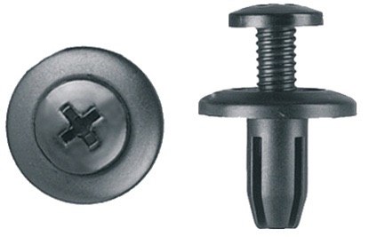
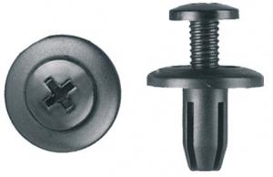
These might be an option. Fits a 6 mm hole and appears very easily removed and re-usable, 5mm holes can be made into 6mm holes pretty easily. http://www.clipsandfasteners.com/Push_Type_Retainer_Honda_Isuzu_Nissan_p/pas1597-25.htm I've gone to the trouble of replacing all my interior plastic rivets with 10-24 insert nuts and matching wide head black machine screws. Tight, squeak free, and totally removable.
-
Two steps forward,one step back. T/C rod length quandy
zKars replied to zKars's topic in Suspension & Steering
Ohhhh! good reason to fire up the lathe! I'll make a set and give this a shot. Never spun anything that wasn't axially balanced. Fun! -
Two steps forward,one step back. T/C rod length quandy
zKars replied to zKars's topic in Suspension & Steering
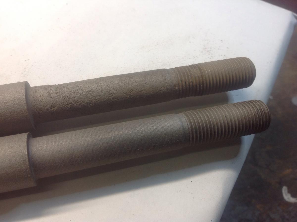
And in the never ending quest to add value to a topic... I had a pair of set of T/C rods from a 77 that were sitting 6 ft away from me as I was doing mine the other day. Of course, I had kept the bushings and washers on there to keep it all together until I had a chance to put them away, and there were the washers just glaring at me in the proper convex to bushing orientation. Did I see that? No, of course not. Anyway... on to the real reason I'm posting this time! The following pictures shows the threaded end and step area of the two spare rods after a quick sand blast for inspection. Which one would you keep and which one is scrap metal? Same car. Scary, huh?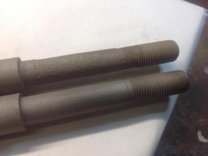
-
Two steps forward,one step back. T/C rod length quandy
zKars replied to zKars's topic in Suspension & Steering
Progress. Well, some. After re-reading and staring at your pictures above, I realized I put the big washers on backwards.Convex toward the bushing faces, not away from. Duh! I tore the T/C rods off and switched them. I also put poly bushing on the back (I know I know) to try to get a little less length due to the offset compression of the bushings. Couple observations. The manor in which the bushings squish is quite different with the washers in the convex to bushing orientation. With the poly on the back, when tightened fully to inner tube contact, the front rubber bushing has squished less (more remaining thickness) then when its washer was concave toward it. Hadn't expected that, but it's true. Other than the rumors of pending T/C failure now, there is clearly ample rubber bushing in front to allow all the TC rod movement I'd ever want or need in any direction without binding or fear or causing undu stress on the rod if the suspension droops or compresses to maximum. My wheel now sits about a 1/2 further back in the wheel well. Turning now does not rub. I also rolled the valence edge a bit further and trimmed the end of the BRE spoiler to give just a bit more room. One could also loosen the valence mounting bolts and slide it forward a bit to gain a wee bit more room. This idea came from some 'guy' in a PM on the topic, excellent advice I might add... -
Two steps forward,one step back. T/C rod length quandy
zKars replied to zKars's topic in Suspension & Steering
Thanks for the input guys, as always, and even CO's desparate and appreciated attempt to point out even the most unlikely assembly option. I've been known to do sillier things. I did in fact use both bolt holes in the control arm. hmmm to fix this, I could put only the back T/C rod hole in the front control arm hole ... ;0 Blue I'm not sure putting the control arms on the wrong side to put the bushing offset to the rear will not help move the wheel back. The T/C rod length determines the wheel fore/aft position so I think you'd only put the control bushing in a nasty out-of-square cramped position and skew the control arm. I realize we are mostly concerned with the bushing joints rotation (up down) stiffness, not the back/front motion, which only happens (and is small) during changes in rod compression or tension, which are transient and only happen when going over bumps or hard braking etc, but its the static position (parked) and resulting length difference that is definitely affected depending on which bushing pair you use. P|R, P|P, R|P or R|R. Same on both will self center the bushings on the frame pocket hole, (stock length), poly front make the effective rod length longer (frame pocket to front hole of T/C rod), poly in back makes it shorter. Well, I'm not putting poly in front, its going to make the rod static length even longer and make my issue worse. Time to trim the valance maybe. I'm not changing tires again! -
Two steps forward,one step back. T/C rod length quandy
zKars replied to zKars's topic in Suspension & Steering
Thanks for the confirmation pictures, I'm now sure I have it assembled correctly. I'm running 16x8 rims, +5mm offset, tires fit perfectly inside the top of the wheel well. Not like they're sticking out or anything that would make this tire rub situation worse. This poly on one side thing is bugging me. I can see reasons why you might want it one either side, depending on whether you are trying to dampen compression loads, like when dropping a wheel in a hole or rut, or when you are trying to reduce caster changes due to steering and damping loads where you might convince yourself to put it in front or the back, or both. My objective is the former, hence my choice of rubber in front. Now when I look at your pics of the bushings with the second locknut, I see rubber bush in the back is not very compressed. This is very different from experience when I put my rubber in front/poly in back. The rubber went damn near flat before I reached lockup length. I'm wondering if you don't have the unit compressed enough to lock the big washers against the center tube (lockup length, like the rear wheel bearings against the distance piece). That would contribute to the nut backoff problem you're having. Also don't re-use an old nylock or crimp nut. I can also see an issue with using one poly one rubber in terms of the relative centering of the bushings and the resulting effective length of the T/C rod. Poly in front biases the rod too long, poly in back makes it effectively too short. It's only "right" when you have the same bushing on both sides. You can use this to your advantage, or you can cause caster problems. I might just be putting that poly bushing back in the back and pull that wheel back. Now back to work. -
Good detective work sir. I was wondering if the second thing isn't something that goes in the spare tire well that holds the end of part of the jacking components or the like? Just has that feeling
-
Two steps forward,one step back. T/C rod length quandy
zKars replied to zKars's topic in Suspension & Steering
Thanks for the input Zed. There is quite a difference front to rear to the fender, pictures may not convey well. I see it in the pictures, but then I know what I'm looking at! Barely 2 fingers in front, fully 4 behind. The wheels are not turned slightly, both sides are identical. Hadn't really considered that the normal position may not be visually centered though. Oh, and a correction, I actually have 205-55 16 yoko S-drive tires, 24.8" diameter. Pretty sure I got the assembly correct at the frame pocket end, one small washer, then a big cup washer, then a bush, then the frame, then last bush, then the last big cup, then the nut. I'm sure I have the nut torqued down so I'm touching and squeezing the central trapped sleeve. No extra there. I also just measured the wheelbase, stock should be 2300mm, I have 2320mm +/- a couple both sides, so that tells me the wheels are somewhat forward. Any more ideas? While I'm at it, let me mention another observation about this process. I considered putting a poly bush on the back side of the T/C frame pocket as has been often mentioned by others doing this, leaving the rubber in front to keep bump compliance. But when I torqued the thing down, the rubber front bush was nearly crushed flat before you get to the lock down point at inner sleeve contact, as the poly bush doesn't even start to squeeze, so that didn't feel right. Went back to two rubber bushings. Can't imagine trying to get the nut on with TWO poly bushings! Remind me never to attempt that foolishness.