zKars
 Subscriber
-
Posts
3,742 -
Joined
-
Last visited
-
Days Won
107
Content Type
Profiles
Knowledge Base
Zcar Wiki
Forums
Gallery
Events
Downloads
Store
Blogs
Collections
Classifieds
Everything posted by zKars
-
Great information about the 15 lb'er. Thanks. One note to all as well, the Fidanza 143281 has a 240mm friction surface but is drilled for both the 9 bolt 240 clutch plates AND the 6 bolt 225mm units. Point is, you are not forced to use a heavier 240 clutch plate to negate some of the weight savings, if all you're running is a nice stockish 2.4L.
-
Details are indeed necessary. In general it sounds as if you are running very lean. This can be caused by many things however, such as too low fuel pressure, incorrect jetting, plugged fuel lines/filter or carb passages, or intake air leaks at the mating surfaces to the carbs or head. Old gas is not likely the cause, its not THAT old. Start by telling us your running fuel pressure (stock mechanical or electric pump?) and your main, pilot and air corrector jet sizes and recent history. Also any other details of how its all installed. Are these new to you? Did it run fine for a while now its bad?
-

Non-destructive rear whell bearing removal
zKars replied to frenaud's topic in Suspension & Steering
First, don't go back to that shop. They were just not interested in helping you. You have three options. 1 Find a real shop with a bearing puller and person who knows how to use it. 2. Go buy a long bearing puller and do it yourself. You need a bearing splitter, and a puller with long bolts. Princess Auto Bearing Separator/Puller Set | Princess Auto is what I'm talkiing about with you going to buy a 3 foot piece of 3/8 threaded rod to extend the length between the splitter and puller. 3. Try freezing the whole thing, then heating just the inner bearing race and see if it will come apart with just a little prying. Remember that while you have it this far apart, you are MUCH better off putting new bearings in there than trying to cheap out and just re-pack the old ones. You will also have the issue of having to re-press on the new or old bearing, unless you again freeze the shaft and heat the bearing, then just gently tap it down in place with a pipe that fits over the shaft and contacts the inner race only. (don't pound on the outer race, it will destroy the bearings). Do you have the torque wrench to put that back together properly to 200-250 ft-lbs? And a new nut? You can refer to http://atlanticz.ca/zclub/techtips/rearwheelbearings/index.html for additional help -
It is actually a 73 model. The VIN, lit pull knob hazard switch, intermittent wipers indicate that pretty clearly. Would need to see the build date on the drivers door tag to confirm. There have been lots of legitimate year "adjustments", just check that ALL VIN's match. Dash, door tag, what's stamped in the firewall above the brake booster, and if there, on the engine bay tag. Would need to see receipts to see how they spent $12K on the engine, and to see who did the work. The asking $$ is not crazy, but likely somewhat high. Depends heavily on the actual underlying rust condition and quality of the current body work and paint, and overall quality of what has been done.
-
I need some dimensions or pic moustache bar area
zKars replied to madkaw's topic in Engine & Drivetrain
This is with an Z31 Turbo R200 w/finned cover. I will check the inventory and see how many poly bushings I have. I can slice and dice a couple and make them available. I also have way too many old nub-less or nub-poor stoppers to use as well. -
I need some dimensions or pic moustache bar area
zKars replied to madkaw's topic in Engine & Drivetrain
I have a report on my m-bar stock bushing replacement. I found that the old stock bushing rubbers were in sad shape. Not just soft, but cracked and crazed like mad. Passenger side was considerably worse. I replaced them with stock ones, but did something similiar to what I alluded to above with my poly muffin top idea. First, let me mention that the preceived softness of the rubber in the old and new bushings aren't that different. I tested this by putting the M-bar in the vise, then putting a large screwdriver through the metal tube in the eye of the bushing and pull/push to get deflection. The cracks and nasty-ness of the old bushings became very apparent. After replacement I did the same thing, and while it was somewhat stiffer, not that much really. I also tested the vertical deflection, which is where the changes were very much more apparent. With the old bushings, when I would jack up the rear end with a floor jack under the diff, the diff would rise a good inch before the car started to move. Between the main bushing deflection, and the soft and not-so-much-there-anymore nubs on the stopper washers that weren't hardly doing anything to prevent vertical movement, the M-bar was free to move up and down WAY too much. When I squish the new stopper nubs with my thumb, they aren't all that much stiffer then a bunch of old used examples I have so I decided to try to do something to improve vertical constraint. Hopefully without increasing noise transmission. I have several sets of poly M-bar bushings laying around, after doing several poly bushing jobs and convincing most folks to stay with stock bushings to keep the diff whine in check. I decided to use only the upper larger OD section of a pair to replace the stock stopper/nub washers. This required that you have to do two things. Remove the muffin top of the bushing and increase the ID of the hole in the bushing to 1" to fit over the center metal tube on the eye bushing. I used a thin cut off wheel (1/16") in my 4 1/2" grinder to remove the top of the bushing (worked schlick, clamped the lower part in the vise and slice away) and then a big 1" twist drill to drill out the center. (its about 3/4" to start with). I was surprised how well that worked.Gives off a neat spider web of melting poly strings as you do it too! I used an old upper stopper (the hole is bigger on the upper stopper) above this poly muffin top, but removed the nubs, all but a thin layer of rubber that I left bonded to the metal washer. THen the muffin top, then the M-bar. The thickness of the poly muffin top closely matches the stock nubs and fills the space nicely with slight compression. I did not repeat the poly muffin on the bottom of the eye, thought I'd try just the top first. So the metal parts of the stack up are exactly like stock, so it tightens up like normal, only difference is the replacement of the nubs on the upper stopper with a donut (muffin, croissant, whatever) of poly. Will mention I have the R/T mount in front with the poly snubber above like GrannyKnot. Ok, enough yakking. Put it all back together, and went for a drive. There were several immediate improvements. 1. Clunks are gone. Diff no longer contacts the LSD finned cover diff brace. 2. Diff whine/noise is actually reduced if anything. Introduction of 'some' poly back there did not increase noise transmission. 3. The drive line is 'tighter'. I used to have quite a bit of slope and chatter back there which I attributed to diff and C/V play, but its all gone. Apparently keeping the diff in place and the U-joints/CV's angles controlled makes for a smoother drive line experience. Imagine that.. Totally shocking news, eh? Now I realize the diff wants to twist, so there is likely reason to have poly both above and below the M-Bar to really constrain it. Given what happened with noise transmission change (ie none) I don't think putting in a lower muffin would be an issue. And its so darn easy to do below the M-bar. I'll complete that and let you know the outcome. Temper this with my comment above re: upper stoppers being NLA from Nissan Canada and Japan, maybe this is a way around this growing problem. Can the lower stoppers be far from extinction as well? At least you can drill out a lower stopper to make it work as an upper (only difference is the through hole, larger on top to fit the M-bar pin OD changes). -
You bet. The resistor wire in the sender is 10 to 90 ohm, Full to Empty. So 0 ohms (wires connected directly together) is just "really full" (or 'Fuel' as you put it ) . No harm. I've been soldering real wires to those nail heads and not putting up with that silly nail head connector thingy for years. One note, once soldered, remember to support the wires really well so that the solder connection is not allowed to flex or experience vibration from wires moving. It will fail shortly if you don't. Solder is good for electrical properties, not its structural strength or vibration resistance.
-
Remove the old crumbled center and spot weld in a nice little bearing with the right ID. Or just swap to a cable system. Much better.
-
The dimples are there to clear the tips of the rubber insulator mounting bolts once the x-member is in place. Put the cross member in place both ways, you'll see the difference in clearance at the tips of the bolts. Other than that, its reversable.
-
You had a trip that went exactly as well as it should have. Congratulations, you have passed the Datsun owners test. You performed the following three official tasks to the judges satisfaction. 1. Went on a trip that was longer than you initially felt comfortable with; 2. Had problems and fixed them so as to continue safely. 3. Got home safe with a sense of intense satisfaction. Oh yes, the un-official one, "Make several un-announced live appearances for the never ending legion of Z fans. Spend time making them each feel important." RE: front wheel bearings. Just follow the FSM for wheel bearing installation. Tighten the nut to 22 ft/lbs, spin wheel both ways, loosen, re-torque, spin again, then back the nut off 60deg (1/6 turn) or a bit more until you get a line up for the cotter pin. You looseness is elsewhere. Even the splines in the steering column are often to blame for that last bit of looseness. Sorry there is no standard list of kinks. Mind you, the contents of this forum could be construed as just such a list.... No one has ever managed to fix them all and drive their Z for more than a week without another one (no matter how small) cropping up. Its as if I'm expecting another problem so you become over vigalent and every darn little squeek miss or sound you can't remember hearing before becomes the focus of the next "problem" you have to solve. Did I say "me" I meant to say "us"....
-
I hate to put a damper on the string method put forth above for toe alignments, but I think there is a critical flaw in the assumptions. To use the rear wheels as a reference, the track width of the front and rear have to be identical. And not just the official track width spec of the car, but taking into account the tires you have on the front and rear. Not all of us have the same tire and wheel size/offset on both end and there may be spacers involved as well. Never mind those of us with 3D adjustable suspension components... I'm having trouble finding a trustworthy source for the stock front rear track width on a s30 this morning (even the FSM body section isn't helping...), but I'm pretty sure the rear is narrower than the front. 1353mm F vs 1346mm R is the only one I could find with a quick google hunt. This puts your strings widening outward toward the front. Easy enough to check, just measure distance between the strings at the rear wheels and out front at the jack stands. They have to be parallel or your front toe settings will be incorrect (not as much toe in as you think). Better to put the strings on four jackstands away from the body, and get the strings parallel and wheel centers evenly spaced to the strings, THEN measure from the tire edges to the string at the front and back of the tire. DIY front end alignment- what's your method? - Brakes, Wheels, Suspension and Chassis - HybridZ And Brian/bacarl, I tried your greased vinyl tiles idea last night. Slick!!! (pun totally intended) It's a lubricating, rotating miracle! All for 4x 89 cents! It also allows the tires to settle outward as well after jacking the car up without rolling the car around. just put it down, steer right/left a few times and everything slides into perfect static position.
-
I have another idea for ya Cappy. One I tested. I have a 73 and I carry the same collapsable spare that you had in your 77 originally. Got mine from a 83 zx, doesn't matter. Since I too don't trust the "can-o-air" I simply bought a small cig lighter powered tire inflator and carry that. To make sure this was a "real" solution, I used it to inflate that collapsable spare. Worked just fine. Not all that fast, but it worked. Then I drained the pressure from the spare. It collapsed right back down to original size. Yes, they are re-usable. One more idea to get something to work. About your 14" space saver spare. Since it fits the front, but not back, you could swap tires if a rear blows out. Put front on back, then spare on front. Remember all of this is for the highly unlikely event of a flat, so a bit of time spent is worth the years of driving with sig. weight savings. I use the extra space around my collapsable spare for critical spare parts, safety gear and nice little inflator.
-
Granny, somewhere on HybridZ there are the part numbers for the Spicer Nissan trans yoke and matching diff yoke that use the 1310 U-joints that allow you to have a custom 3" steel or Auml driveshaft made that result in an unbreakable and if you should EVER need to, replacable anywhere u-joints. If you're having one made, why not? Here it is! R200 Differential to Drive Shaft Connection - Drivetrain - HybridZ Well that's close. There is another. MSA sells a 3" Alum replacement shaft as well. Probably made with the same parts
-
Ed, glad to be of service. I love a good mechanical mystery. Having a bunch of spare parts has come in very handy in many such instances. Let me know if I can be of any further assistance. The only other suggestion to make the install process easier for customers might be to clock the drive adapter differently so that it matches the stock position of the drive spindle. Plug #1 is now 60 or 70 degrees clockwise of where it sits "Stock". This forces the user to reposition plug wires which may leave some too long or too short and since the cap is so much smaller, there is less room for plug wire weaving games. I did mine like Grannyknot in post #36. You could also choose to laboriously move the drive spindle which means dropping the front sway bar also and dropping the oil pump. Messy and not for everyone. Move it one plug position CCW (looking from the top) and it would be just fine. Next batch, eh? There are also no less than at least three different distributor bases on various s30 engines, each with their own position of the hold down bolt. This in turn affects where the new clamp plate is located, which could bring up access problems to get the allan wrench on that clamp bolt. I have the zx E12-80 base on my engine, and position and access were good. Don't forget you can flip that new clamp plate over and point the bolt a different direction if you need to. Since you'd probably like to plug in the USB cable at some point to play with maps, think about where that port is located when you're done and how you'll access it. Remember too if you're driving and tuning with the cable in, there is no moisture seal around the plug. Don't tune in the rain or pack some chewing gum around the plug Hmmm, Juicy Fruit... Reading back to comment from mDec about actual verses map timing mismatch, I found that I have a near perfect match between the advance map and what my timing light shows on the damper. I did set mechanical TDC very carefully and set the little green light to "just" come on with CW torque on the rotor as suggested, during initial dizzy positioning. I suspect small errors here translate in larger problems with the real verses map.
-
Steve, with all the discussion and testing, perhaps you have forgotten the role the accel pump has in transitions? Perhaps you need to move that teensie weensie cotter pin one hole up to get some more squirt or up the size of the old pump jets? Just so's you know and as way to say thanks, all this discussion has helped me to finally go deal with my 44's little "annoyances". Seems I only had 2/6 pump jets squirting anything at all... Plugged knozzles on the jet outlets. Had to ream them out with a fine SS wire strand. While I had them out, of course there were other little lessons learned and points to mention that I'd thought I'd share. 1. I discovered that it's possible, (not that I did this, well, ok, once during troubleshooting...) to assemble the pump block with the cover that faces the carb body reversed 180, which would render its output useless. Check the gasket and body to ensure you align the outlet with the gasket and the gasket to the outlet hole in the body so the squirt has someplace to go. 2. The condition of the pilot screw taper and its seat can vary all the way across and drastically affect just how many turns is "right" for each cylinder. While I had the carbs off, I was checking the throttle blades for consistency and noticed that one side had the pilot screw tip just poking through, while the other was no where to be seen. I checked that both were the same 1.5 turns from "closed". what a difference. Who knows what the flow differences are. My 44's are oldies, they are the "Q" roadster type, and were old when I got them, so even replacing the needles might not help all that much if the seats are worn as well. How to adjust them now? At least I know the relative positions of the tips on each so I can compensate some, and the rest is by ear. What matters here is the available cross sectional area at the hole into the throat, and how much needle is filling it at just that position. 3. Everyone knows how nice and stinky these things are, fuel stink seems the norm. The bottoms of my carbs were quite fuel-ie and stained, almost to the point of being wettish. Can't imagine the stink that I will have now with 6 really strong accel pump shots every time I touch the gas pedal! I think I have a bit of a solution though to keeping gas on the inside. The base of the carbs have four locking bolts/nuts/bend-over tabs that retain the chokes and venturis. Being on the bottom, they naturally will let the inevitable puddling fuel seep out the bottom past these threads. Just a touch of thread sealant (rtv?) on the threads when you put them back in will help alot. I hope... I love the "turn off the pump exactly one fuel bowl's worth from home" approach. Nice. 4. Transition holes and their location and idle settings. One thing that is not clearly covered in the Mikuni manual deals with mechanical idle settings. Webers have this issue too. It's mentioned briefly above. There is a terribly fine line between throttle blades closed (no idle possible), throttle blades open just enough to get some kind of low idle speed, and too much throttle blade open that exposes the first (or second!) transition holes. To get idle mix right with JUST the pilot screws you need to have enough idle to keep the car running, but NOT have the blades open enough to expose that first transition hole in the roof. With the carb in my hand, from closed blade to first trans hole 'just' peeking open is BARELY one full mechanical idle speed screw rotation. If you have a lumpy cam, or things aren't tuned close to right yet, you get VERY tempted to turn that idle screw up some more to get the dang thing to run while you twiddle, but DON'T DO IT! Exposing the transition holes while tuning idle will likely give you that flat spot in transition off idle, which will make you increase you pump shot or pilot screws turns out, but you're chasing your tail at this point. Take one carb off and determine how many turns you have until that first trans hole pokes out on the manifold side. It also shows you exactly where the mech idle screw starts to move the throttle blade. If you have to have a higher idle, I'd be plugging that first trans hole. 5. If the carbs aren't new, or you didn't get your jets from a known and reliable source, don't trust they are all the same size! Well mine were, but the mains were half 150's and half 80's! yup, 80's, at least that's what they said on them. But the 80's had been drilled to 150's.... Thanks to Todd for pointing out that possibility. Also later discovered my pilots were half 60 and half 65's, again, 60's were drilled to 65's. Drilled jets don't perform as consistently as factory jets. This thread pretty clearly indicates how small changes make big differences in performance. Don't need to have inconsistent jets too. 6. The short 5mm screws that hold the stock Mikuni linkage to the body. I discovered one I had substituted was just a hair too long. The choke in that one barrel now has a very slight extra 'wave' in it. Let's just call that a "venturi laminar flow disturbance" experiment.... Also the same holes exist on the other side of the body, and one at least empties right into the barrel behind the choke on that side. Does this cause a slight leak around the choke from the outside? Maybe, plug them (with SHORT 5mm bolts!) 7. Jetting for different displacements. It seems the "right" jetting for 2.4 and 2.8L engines discussed here are pretty much the same really. If I had to average what I've read above, would it be 190-200 air, 150 mains, 60-65 pilots?. I have a 3.1 stroker, but I'm using the jets as the rest of you. I have 34mm chokes. No, bigger engines do not simply need bigger jets or bigger chokes. Its about being able to supply enough fuel to supply the air flowing through to keep the APR's where you want them. 8. Get your timing, idle vacuum, engine temp in spec and carb/mani and mani/head gaskets sealed before proceeding with any carb tuning. Can't imagine how I tuned these things before without a wideband and vacuum gauge to refer to. What does vacuum on one runner of six mean anyway? What if you have a lumpy cam? Retarded cam timing? A subject for another post. And Mitchell, that plug reading chart is something we should ALL commit to knowing by heart. Thanks for posting it, as well as the other references. Great stuff.
-
The spring under the head is supposed to keep the tension. Its worn out or broken. Replace the spring, or add a washer to increase the pre-load.
-
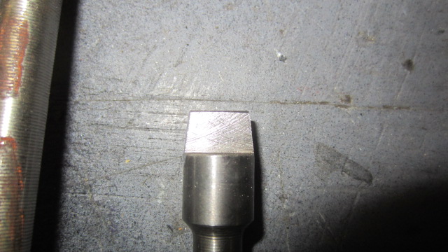
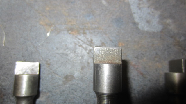
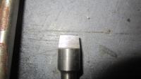
Ed and everyone.I just got in from the shop. I know what the problem is, and its NOT too small an ID!!! The rectangular slot in center is TAPERED narrower as it goes deeper in the body of the dizzy. The tang on the spindle that engages it is NOT tapered, so depending on how much your particular tang is tapered from wear, it may or may not fit in. I have 7 spindles here and NONE expect one fit. I measured and measured sizes and all were identical. But two of them fit better than the rest. Once I saw what the difference was, ie one had a very worn (and hence tapered) tang, the pieces fell into place. I ground one tang down to taper it toward the tip on both edges and it slipped right in to complete engagement depth. Ed you have to re-machine that tang slot so it stays at the same width the whole way down. Those of us with dizzies have to pull the drive spindle and taper the tang. Reducing the width by .05 at the end compared to where it end being cylindrical is all it will take. BTW every one of the 7 spindles had an identical .4885 OD to the cylindrical section. The dizzy was already .4950 or better ID, so it was never the problem. Here is the picture of what I had to do the tang. I'm pretty sure t'is more of a taper than I needed to create. This is the best spindle I have for comparison (center). Note how straight the sides are. The one on the left has a badly worn left side taper. I just about went all the way in with no pressure. The straight sided one would not engage the slot AT ALL.

-
Nothing better than knowing you're not alone! Thanks for the quick response, Mike. I'll let Ed know directly so he keeps on top of the problem. I'm sure he'd like to know why the drive end is all ground up if I ever return it for waranty work! Mine was purchased in the last 3-4 weeks.
-
Carefully consider your reasons for wanting rear disks. If you're keeping your stock wheels and hub caps, it can't be for appearance reasons. Properly set up rear drums with modern friction materials are all you need for street driven Z. Concentrate on upgrading the front brakes first, but again, like-new condition fronts with great pads are ALL you need for the street. Yes, really. Make sure your master is up to snuff, fresh fluid, and a proper bleed. Make darn sure you keep the front / rear relationship safe. Last thing you want is more rear than front. Do some more research and be honest with yourself about why you want disks in the rear.
-
Hey gang, this weekend it was my turn to put in my fresh and purdy 123 Ignition dizzy. Few details to share. Generally the install went as described above. Schlik. Love having only a few degrees advance for starting, and full MAP compensated control. But there was one gotcha. Read on. My issue is with the fit between the end of the drive spindle in the front cover and the base of the new dizzy. Its WAY too tight. When I first put the thing in, I had trouble getting the rotor to lock into the drive spindle. I really had to reef downwards while twisting the rotor to get it lock into the slot. Even then when it finally did catch, it felt like it just barely engaged. I went around to the passenger side and looked to see if the dizzy was all the way down. Nope. Its up about 1 to 1.5 thicknesses of their nifty little lock plate too high. Sorry no pics but its clearly not even close to all the way down. I removed it and grabbed a spare spindle I have laying around and sure enough, I could only get the thing all the way engaged by tapping it in with a hammer, (which I only did about 0.05) as I would likely not have been able to remove it with more force than I wanted to use. I measured the end tang, and its mating slot in the dizzy, they can fit okay, but the outer diameter of the shaft and ID of the dizzy are very tight tight interface fit. Now I appreciate a tight joint for this application, but I can't seat the dizzy without rubber hammering the body down (didn't do that, but would have to), and then I am sure it would be a royal bi$!)h to remove it. At the moment, I have not resolved this, but it seems like a little reaming/Dremel drum sanding of the ID of the dizzy to make more room for the shaft is the easist solution. I'd rather not remove the spindle and reduce its OD. It also possible that the location of the slot in the end of the dizzy is slightly "off-center" (I know its not in the center) so that as the tang begins to engage, it is pulled sideways and locks the OD against the side. Doesn't feel like this is the case when I play with the spare shaft on the bench, its just crazy tight going in. So what say you other users? I want to hear from Mike W, Granny and mDec and tell me your situation. Did you have similar problems, or did yours schlip right in like nothing? Maybe you should go out and check if yours are really seated ALL the way down! The base of the dizzy plate and their new lock plate below that, should be totally flat to the front cover mounting surface. No gaps allowed. If your dizzy body is slightly wobbly when you push it side to side, then its not all the way down. Since Mr. 123IgnUSA is watching/listening to this thread, any similar reports from other users? Jim
-
Safe distance from salt water for parking a car
zKars replied to Mikes Z car's topic in Open Chit Chat
You could take a freshly sand blasted datsun fender and put in the full sun in the Mohave desert in August, and it would be rusty in 72 hours.... If you want to get all scientific about it, Air + the earth and its oceans => wind => clouds => humidity => rust. Fast or slow, its gonna getcha! -
We are going to need a picture of these wheels. The only Nissan alloy wheel that came on North American 78 280's is not a "turbine" style wheel. http://www.classiczcars.com/forums/body-paint-s30/21653-newly-painted-280z.html post #13 shows the wheels and hub caps there were the only factory options in 78. Someone else was asking about center caps a couple of days ago. There were several suppliers mentioned.
-
There is your problem right there. 4.5 turns is a million too many. Rich rich rich. Your plugs are loading up and this is causing your poor performance during actual use. Please, just humour us, put them at 2.5 and spend a day with it. I will gladly be wrong if this is the not the issue. From there, please get access to a wide band O2 and a vacuum gauge, and stop guessing about what the problem is.
-
Check for vacuum leaks as well. Tighten the carbs down, check the manifold bolts too. Are both enrichment knobs turned out the same, and approx 2 1/2 turns? Don't blame the carbs until all other aspects of the tune are corrected first. Timing, valve lash, vacuum leaks, bad plugs, low compression, bad wires, cap etc are all out of ztherapy's control.
-
I need some dimensions or pic moustache bar area
zKars replied to madkaw's topic in Engine & Drivetrain
How about this? Replace the stock nub washers (they are called 'Stoppers' in the fiche) with thick all-rubber washers. This replaces the stock nub washers compliance with more rubber, thicker than the nub washers so they compress when tighted down, and you have a chance of using different durometers of these washers in a effort to both increase stiffness and maybe affect sound transmission. No danger of metal washers coming in contact with the center sleeve. Hey, get real fancy and make multi-layer washers with different density layers to reduce sound transmission (each density change creates another reflection interface). You knew we'd have to start re-engineering this and start using 2$ words, didn't you? One source of really tough rubber washers of the right diameter and thickness might be the muffin tops (sliced off) of a set of poly replacement MBar bushings...