zKars
 Subscriber
-
Posts
3,742 -
Joined
-
Last visited
-
Days Won
107
Content Type
Profiles
Knowledge Base
Zcar Wiki
Forums
Gallery
Events
Downloads
Store
Blogs
Collections
Classifieds
Everything posted by zKars
-
Other than some apparent ratio differences in the early rack, all racks are interchangeable 240/260/280 to the end of 280z. There is only one uniqueness, and that is the size (width) of the bushing flanges and bushing, the left one near the steering shaft . Early racks are narrower, later (260 onward approx?) are wider. You just need the correct width bushing. The energy suspension poly bushing kits for the 240 and 280 are only different in the left rack bushing width. 7.10101 (240) and 7.10102 (260-280). I wish I could remember the flange width on the two models, let me go measure some.
-

FS5W71B Rebuild Thread - Tips tricks and discoveries!
zKars replied to zKars's topic in Engine & Drivetrain
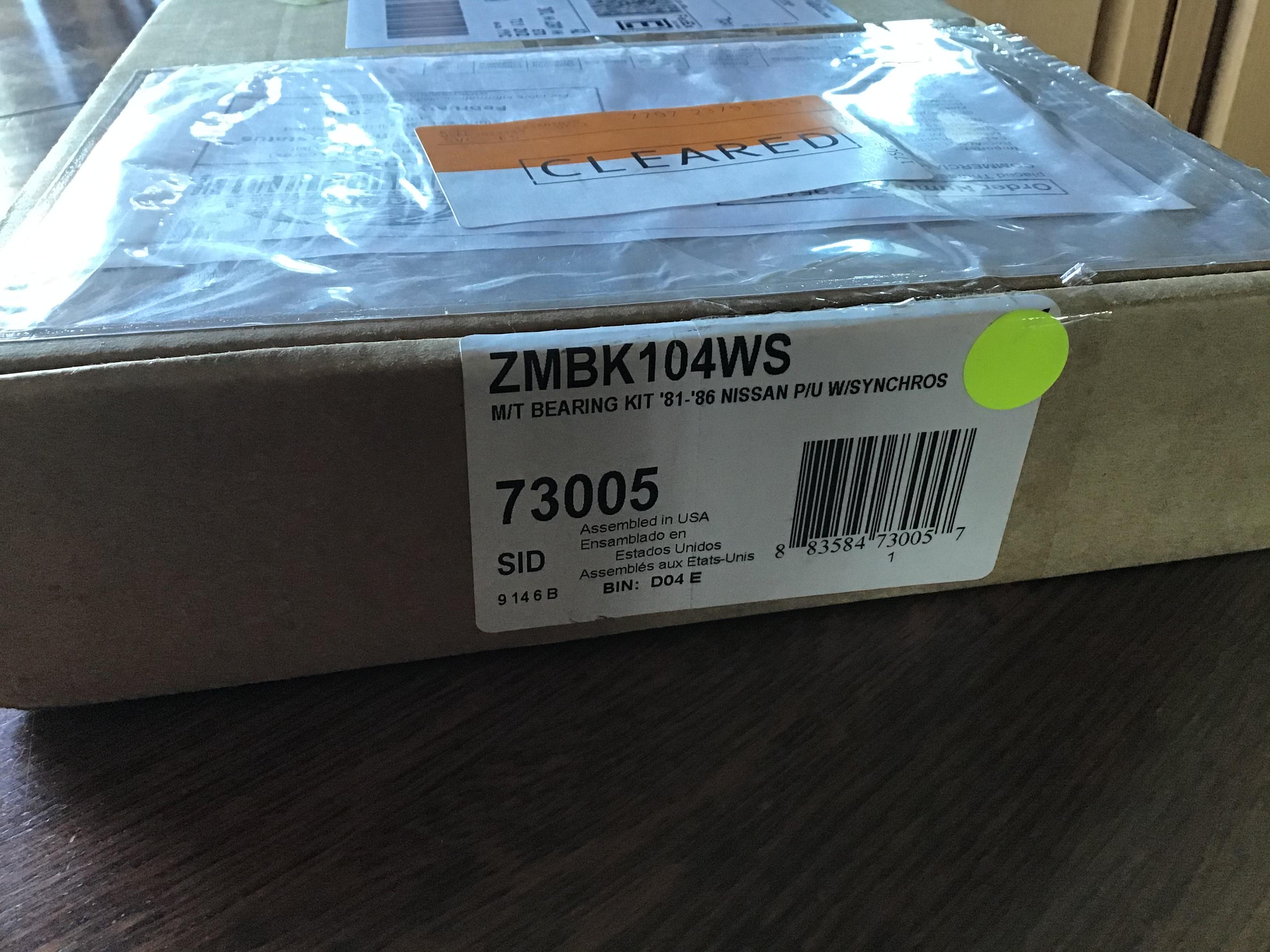
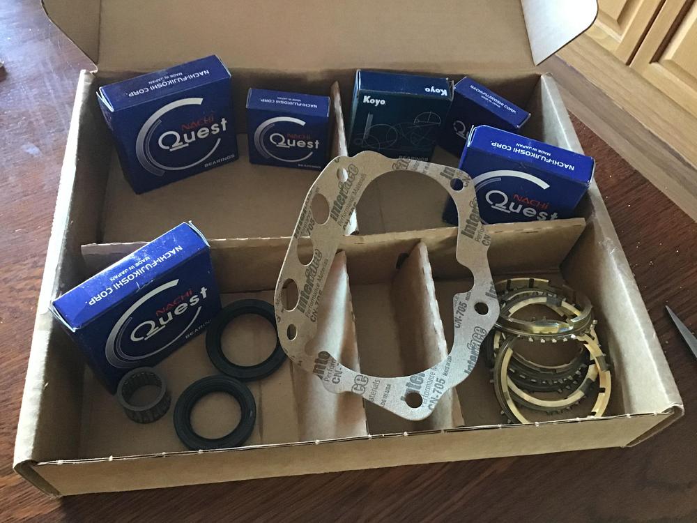
The Doctor is now in. Finally. Today’s news is about rebuild kit pricing. I have actually found a cheaper source for the Bk104WS kit. Rockauto! I found the kit when looking for 200sx parts (don’t ask, it’s what’s been keeping me ‘occupied lately) ZMBK104WS is the part number. Was looking under 1980 200sx. $87.37 CAD ($66.76 USD) and about $25 CAD shipping. Expecting to be buying cheaper quality parts, I waited until they arrived. Well they are here. Everything in the box appears to be identical to the other kits from drivetrain.com and transpartsdistributors.com. Okay, one bearing is a Koyo rather than a Nachi. Everything else appears identical. Got here faster than the other kits too. One week vs two. Now if I can just store away of a few thousand 510 parts that just showed up, MAYBE I can actually rebuild one of these dang transmissions! Arggghhhhhh!!!!
-
Hatch alignment can be a pain in the glass... sorry. I would suggest removing the main weather stripping and getting the hatch to fit without it. Not an easy decision, but it will remove the main impediment to adjusting things and being able to tell if your adjustment is doing what you think. The hinges do have a L and and R stamped in them somewhere. Do make sure you have them on the right side, though I’m not sure why them being wrong would cause one side to be higher than the other. You never know.
-
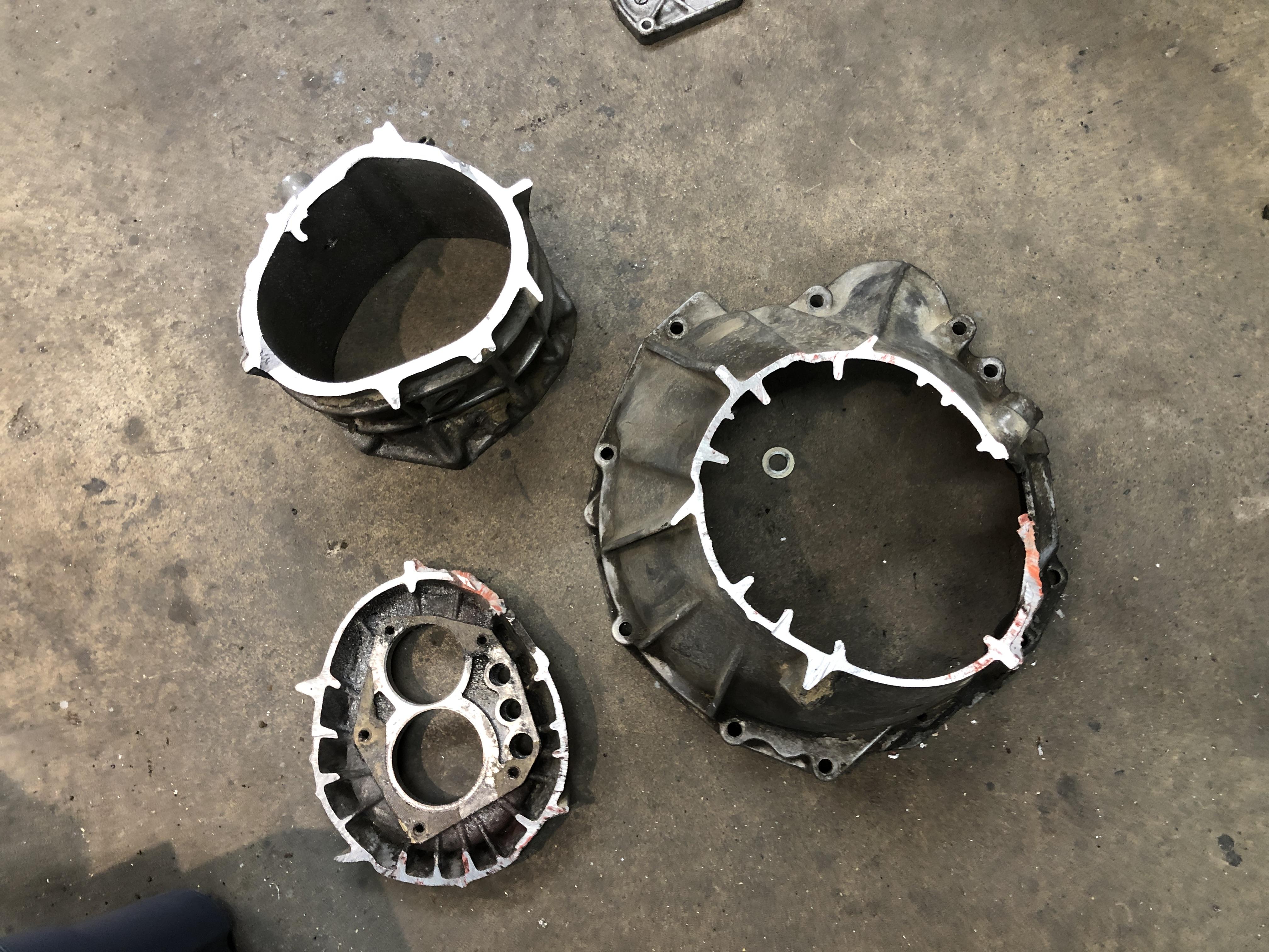
Ron, PM me. I have that other thing in an envelope waiting to get to you, I can add a housing and cover. Yes, all two bolt covers are the same across the years. There must be eleventy five variations of the lower housing though....
-
Once it thaws a bit here I’ll go sift through the dizzy spares and see what antiquities I can resurrect....
-
I have a bunch of those. Send me a PM and we’ll exchange info.
-
Stock length Z31 turbo axles do not fit the s30 chassis, as you are finding out. The shorter of the two can ‘just’ fit the long side if you’re lucky. This has been an on-going discussion for years. Someone made a set of shorter axles shafts discussed on hybridz.org. Jon Mortensen I think? Long since un-available. Driveshaft shop has a solution I think.
-
I think the short nose R200 started with the Z32 in 1990. The much sought after CLSD’s with the finned covers from the 87-89 300zx turbo’s were long nose.
-
You are correct.This is for my Haltech 750.
-
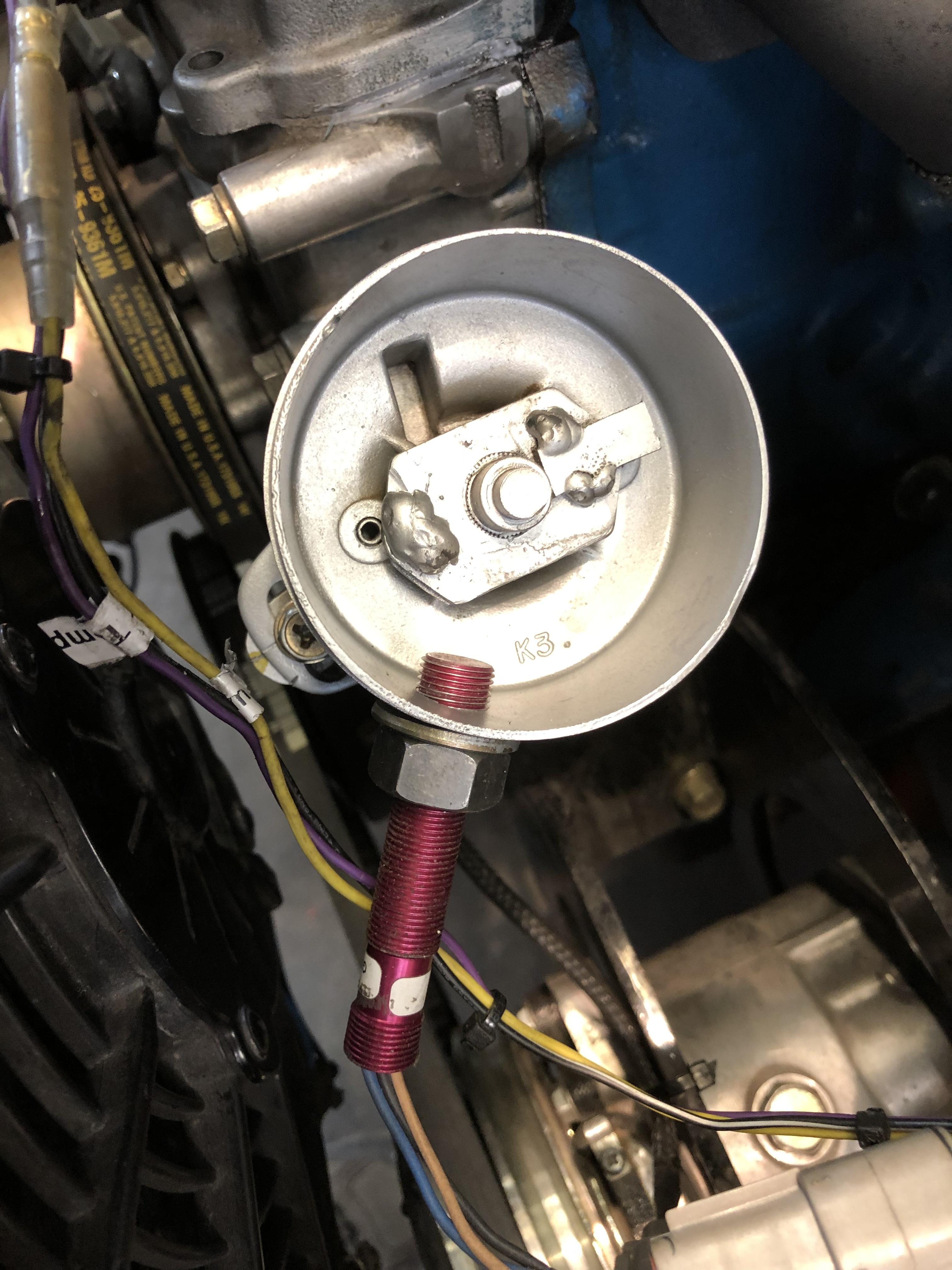
So simple. That “Was” a points dizzy I think. Any, including an L4 dizzy can be used. Once you take it apart, the plate at the bottom had the two pivots for the advance weights. cut the shaft just above, remove the pivot posts, weld on a little square chunk of metal, a weld blob on the other side for a bit of counter balance (very scientific). Machine the case down to just above the cutoff point. Drill a hole for M12 x 1 thread on the sensor at the same height as the new welded on tab. Come up with a lid. I machined a lip to make a 2.75 OD in the case. You can just leave the stock dizzy cap if you want and not shorten the housing at all. If you start with an L4 dizzy, you can get some great looks when folks count 4 towers, let alone that there are no wires. Best thing is, timing doesn’t matter! Only one wrong place for the sensor line up, ie the exact same spot as when the crank trigger is at the missing tooth. ECU can’t handle that. I have a few spare dizzy’s. I can make you one.
-
You can get pretty basic triggering with an old dizzy, a spot of welding, and a hall sensor. DIY baby! You don’t even need to thread the hole for the sensor straight! (Yikes!) Yes, there is a trigger wheel on the crank as well.

-
Sorry no tricks with the bearing, but I have a trick to putting that C clip back on. You put your back into it, literally. Get one of those 1” wide tie down ratchet strap things, sit in the car, put the steering wheel retaining nut back on the tip of the column. Wrap your tie down strap around the threads behind the nut, sit a bit forward, then wrap the strap around your back under the arms more or less, and tie it off back to the column. Then get the snap ring tool ready, (you did put the snap ring on the shaft before the nut and the strap right?) just lean back and pull the column toward you. Put the snap ring back on, then lean forward to remove the tension. You’ll be surprised how easy it is. After you realize you can’t undo the knots you made, wait for your wife to discover you in the garage and set you free. Prepare an appropriate story of how you got that way, while you wait, then invite her to tie herself to the glove box so you can do something together for once.
-
FS5W71B Rebuild Thread - Tips tricks and discoveries!
zKars replied to zKars's topic in Engine & Drivetrain
No gib locks. Something I do miss. I put duct tape over the gap where the scales and the indicator on the adjuster wheels meet to prevent rotation of the handles if I run into one. Hardly ideal. I can come up something better. -
FS5W71B Rebuild Thread - Tips tricks and discoveries!
zKars replied to zKars's topic in Engine & Drivetrain
All great feedback, thanks. Yes the 4mm measurement isn’t the be all and end all tell tail of your success, correct initial centering in the existing hole is your best defence. Another idea to getting the bearing to center itself when getting started, is to un-clamp the housing from the base so when you push the bearing through, the whole thing can easily move around, rather than using the X/Y adjusters with all the above mentioned rubber play in everything. Go in and out a few times until it settles, then carefully and evenly tighten down the toe clamps to lock the housing to the mill table. Maybe I need to get some good precision DRO X/Y readout on the table so I can accurately locate the center of both holes then compute if the distance is close enough to 71mm before AND after the hole is enlarged. -
FS5W71B Rebuild Thread - Tips tricks and discoveries!
zKars replied to zKars's topic in Engine & Drivetrain
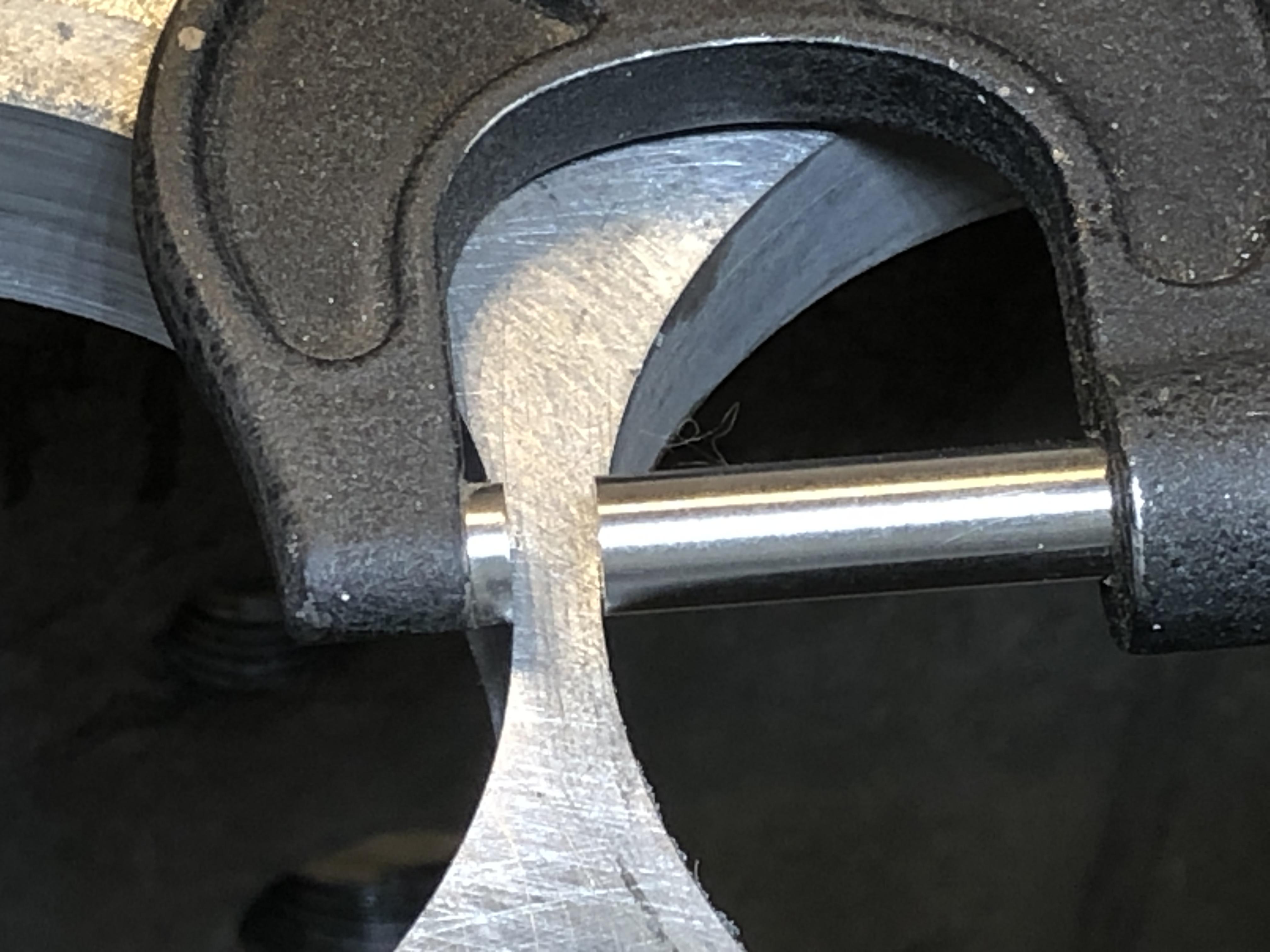
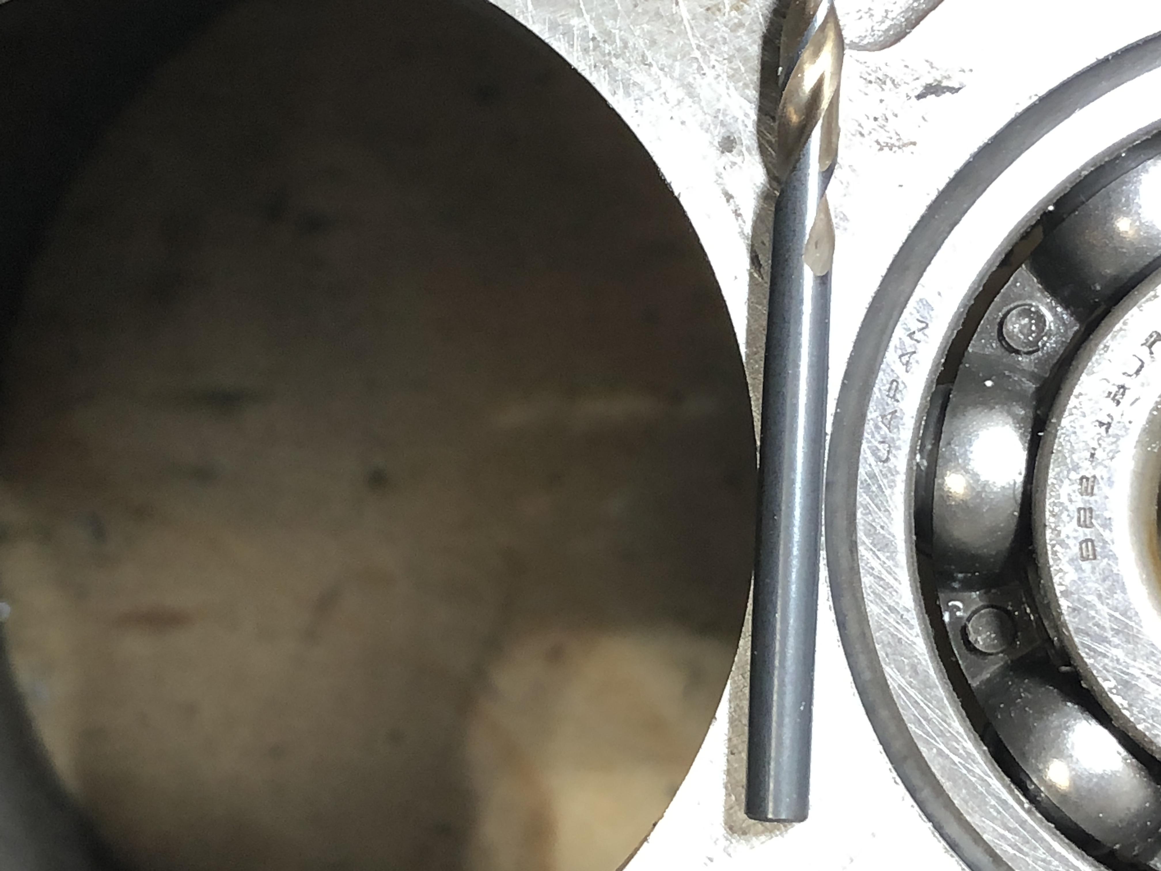
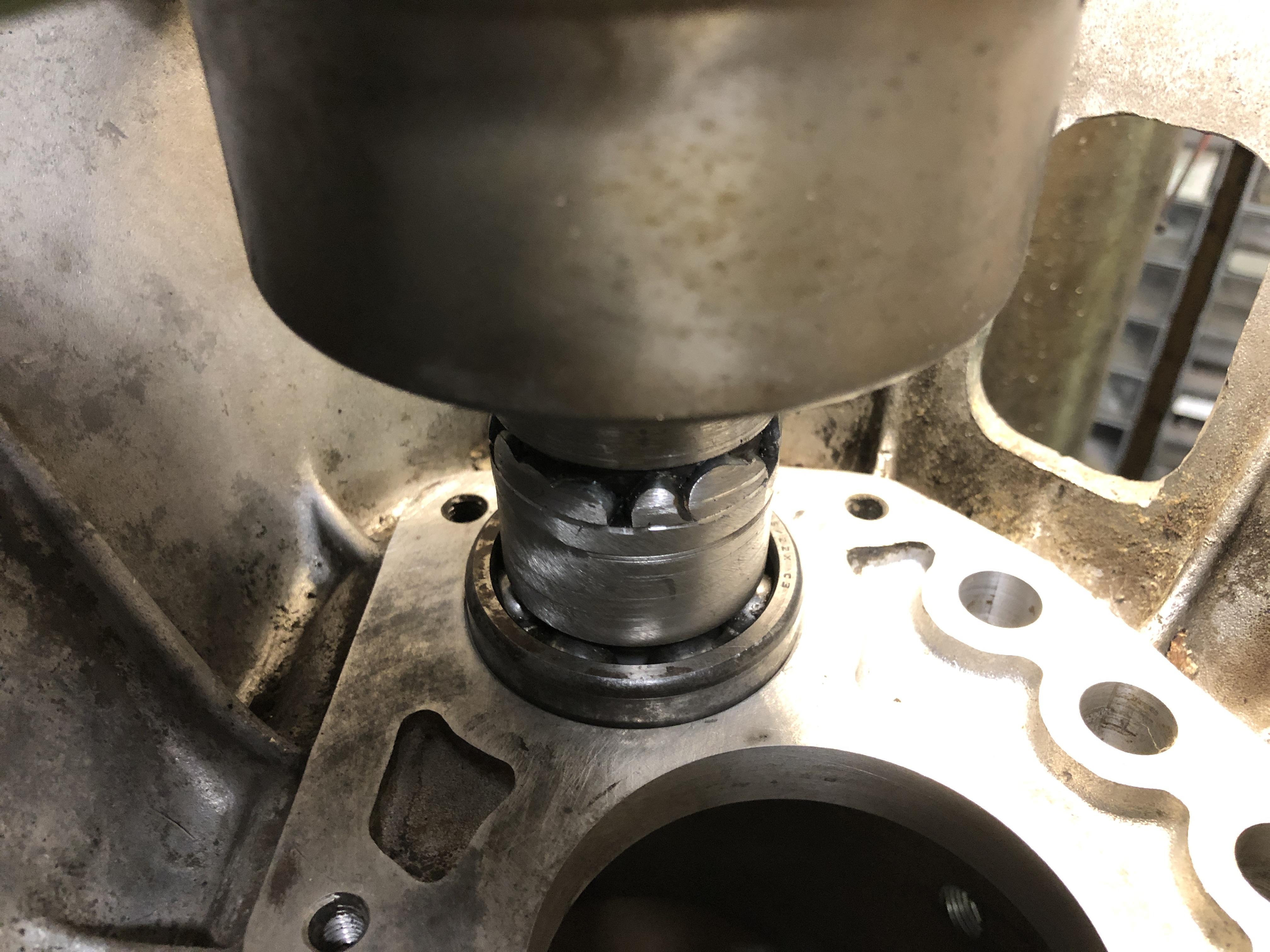
Well, the first real 62mm hole in a real 4 speed housing has been bored. The bearing fit is a nice tap-in, just like the Stock C type hole, and the location is as perfect as close as I can measure. There is exactly 4mm between the two bores. One slight issue that may lead me to use the coax indicator instead of the pilot bearing for centering. Maybe. This time, when you first move the bearing up/down into the 56mm hole with the quill and start moving the table X/Y to get the bearing to slide nice and evenly in the hole, there is quite a bit of X/Y motion possible with the bearing still passing through. You have to listen very carefully to get the least drag noise, and to get the minimum quill effort. This is not slop between the bearing and hole, or bearing on the mandrel, this is the table motion deflecting the casting on its plywood base I suppose. It’s pretty easy to get close. I drilled the hole, it worked out fine, BUT there is a clue that I was not perfectly centered. The bearing stays engaged with the old 56 mm hole until you are about 75% of the way through, then the bearing pops out the bottom, and is no longer supporting the quill location. At that moment, you can see a mark around the circumference of the bore. It’s tiny, I can’t feel it with my fingernail, but I can see it. So the bearing was not dead center to start with. Maybe its just a remnant of the motion induced when the bearing left the bore. Oh so close. Measuring the 4mm space between the two bores is tricky. My caliper is too long. So I set my micrometer to 4mm. You can’t measure that thickness with two curving walls, so it’s resting on top. I need to make a 4mm gap gauge of some type. This is a 4mm drill bit. Parallax is a bitch.... picture is not perfect. This is the 62mm bearing in place.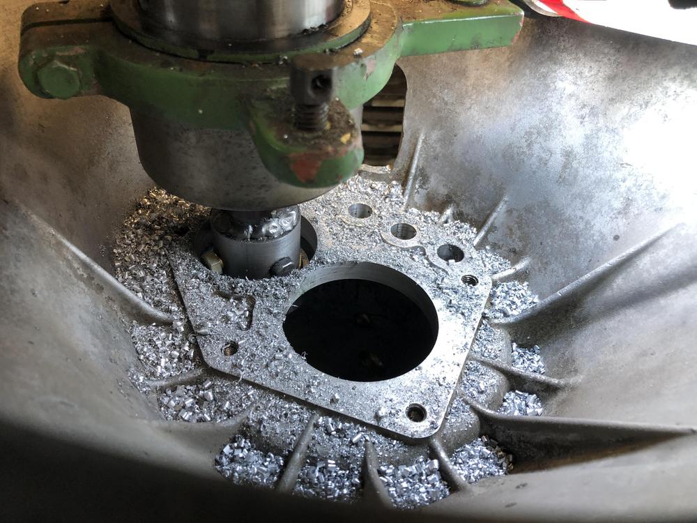


-
FS5W71B Rebuild Thread - Tips tricks and discoveries!
zKars replied to zKars's topic in Engine & Drivetrain
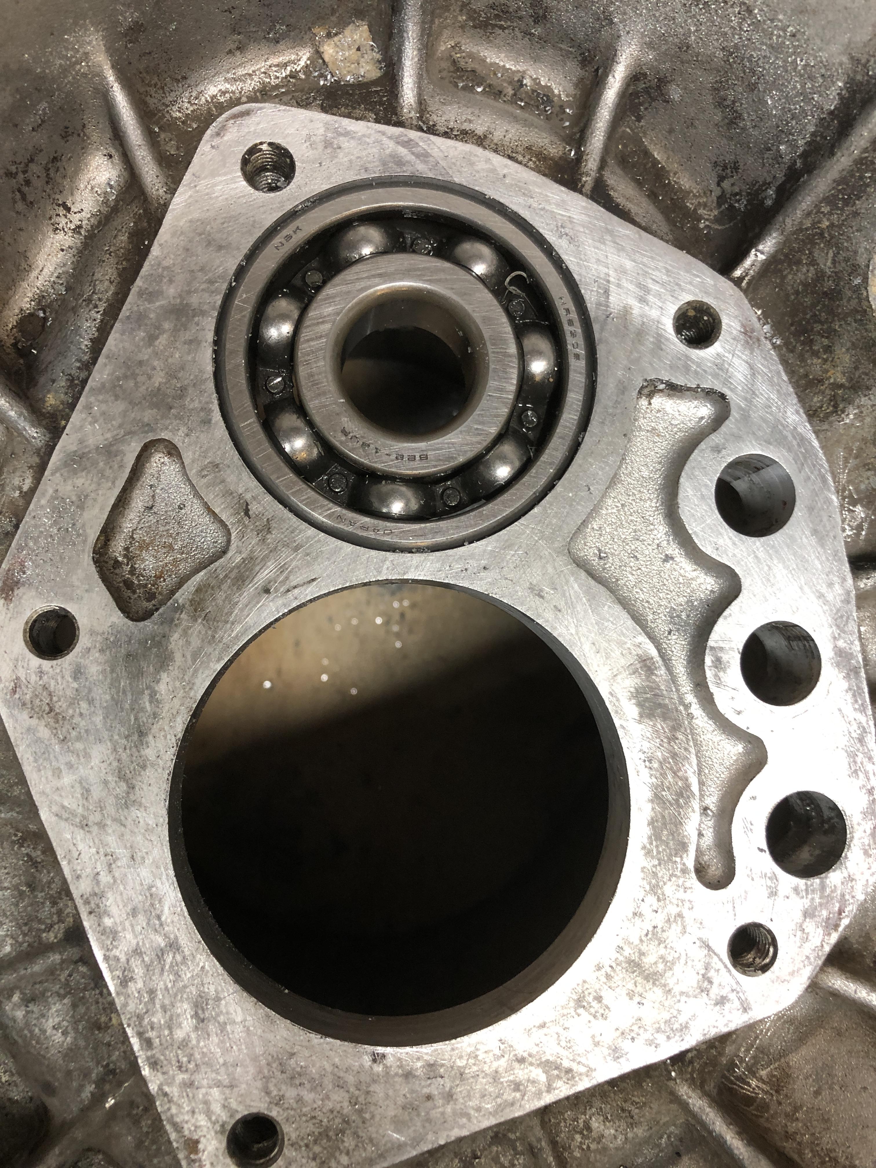
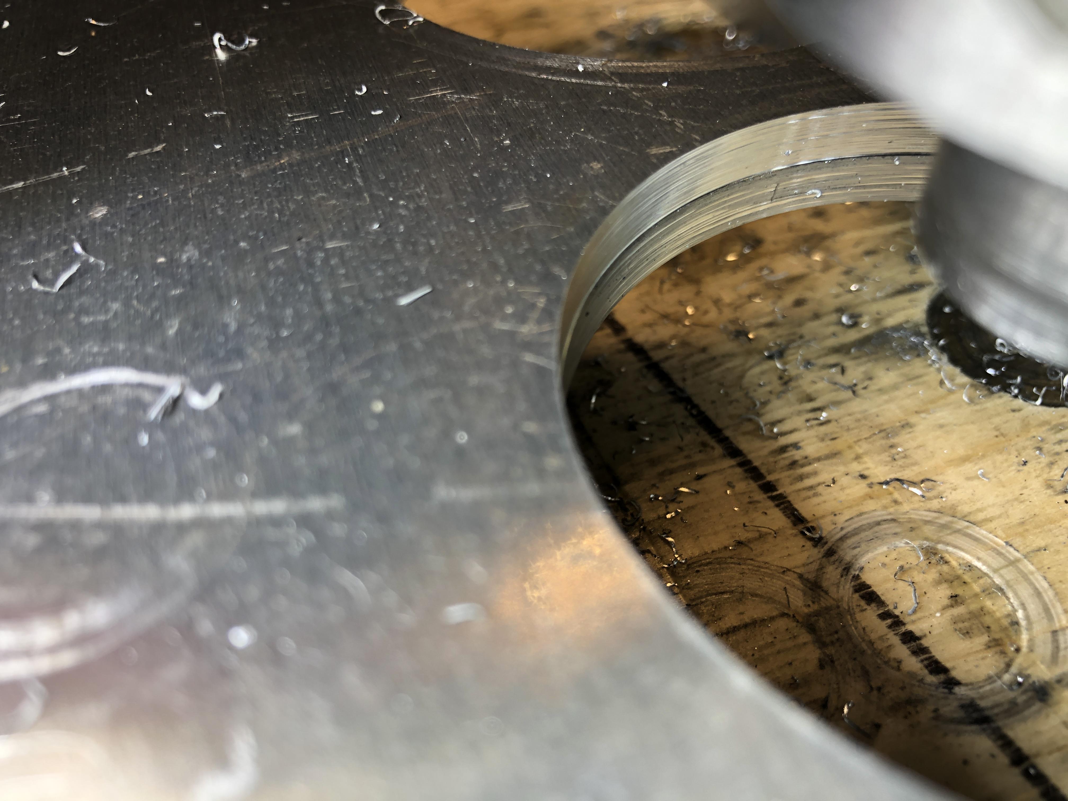
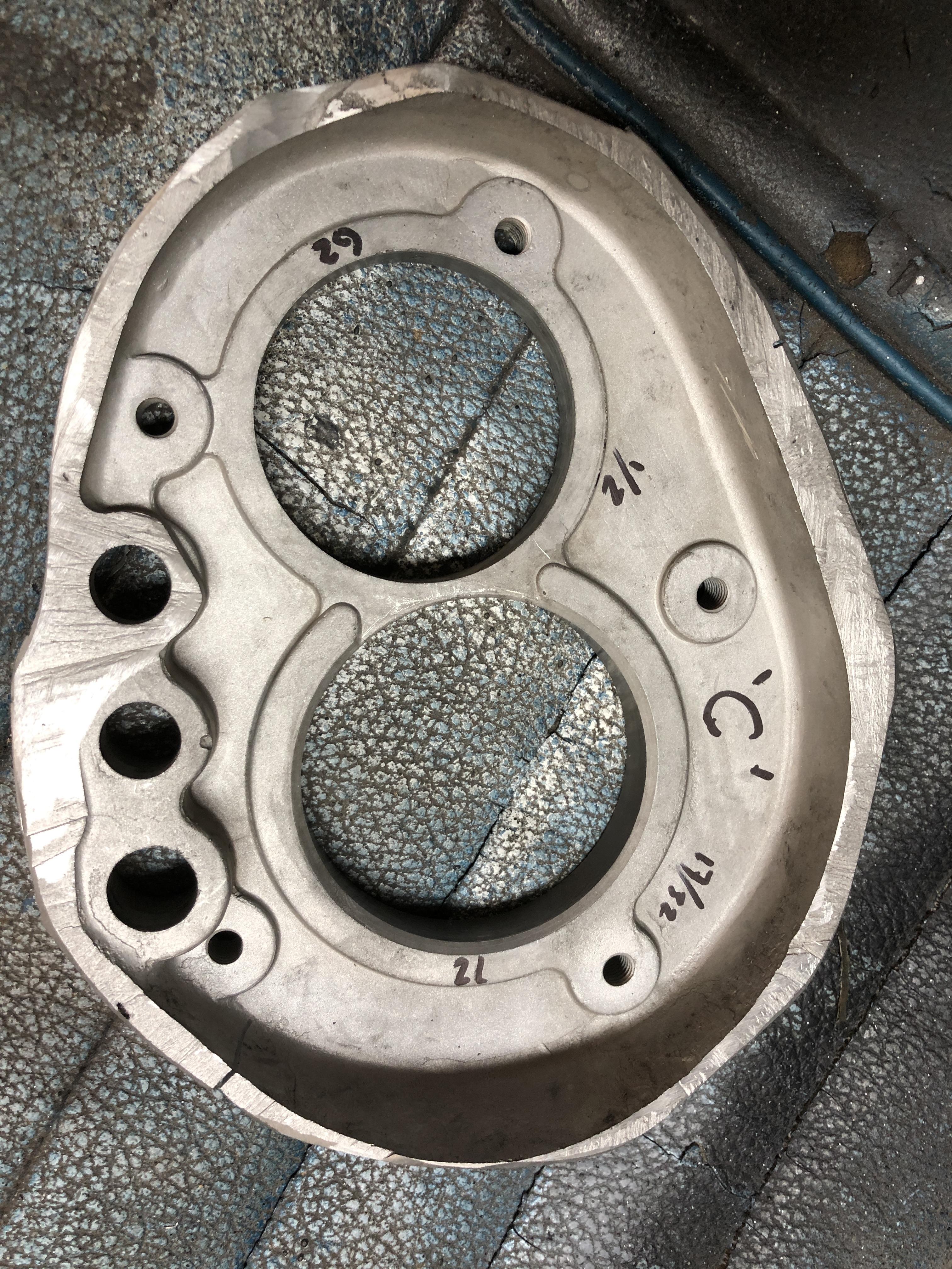
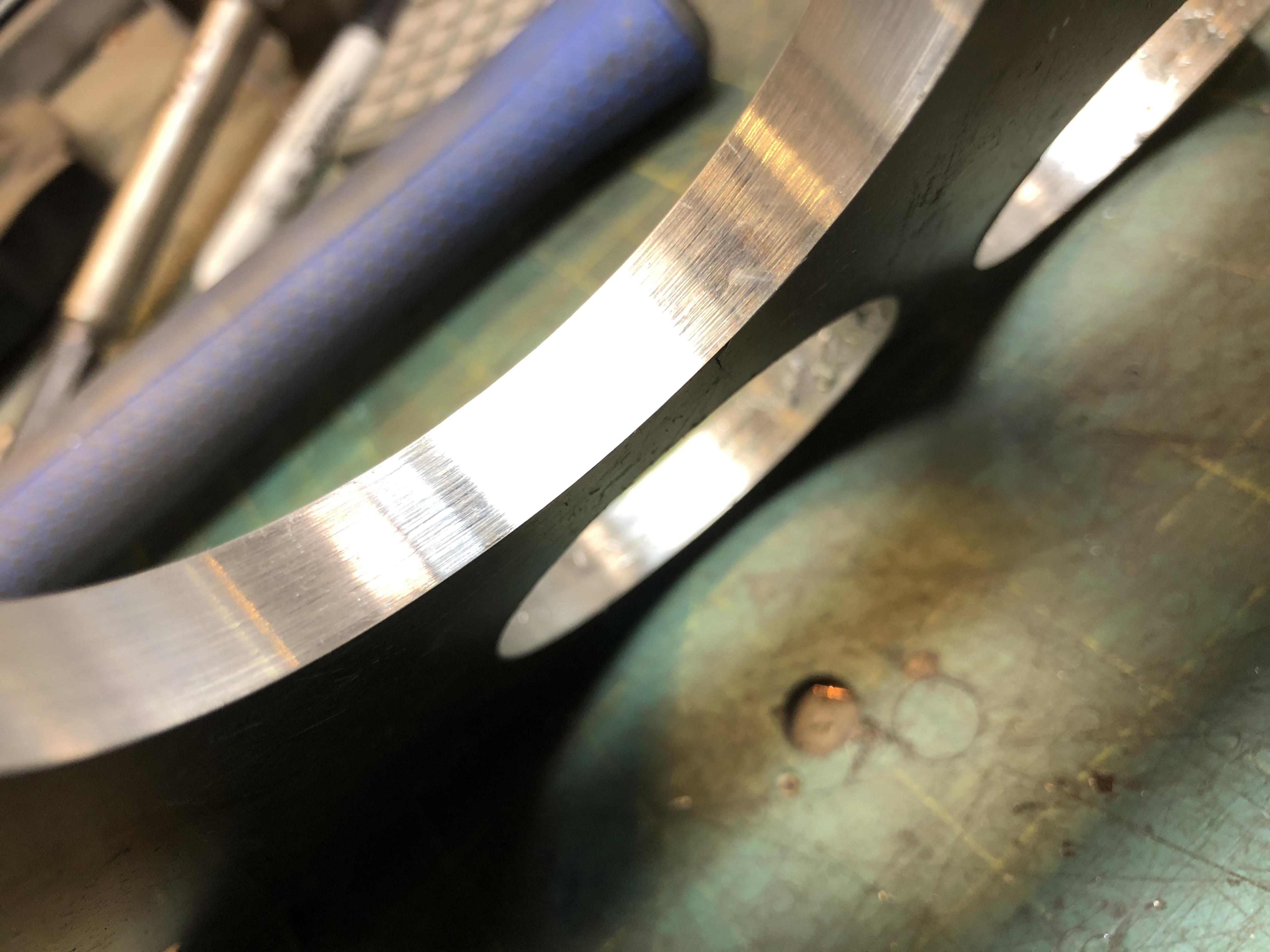
Success! Only took 5 tweaks of the cutter position to achieve hole size Nirvana. It has that nice rough scrapie sound as the bearing easily pushes through the hole with the drill quill. Such as easy test. Drill through, slap the 62mm bearing on the bottom, and push it through the hole to see how it fits. You know immediately if its the right size or not. Since I was starting with a 57ish mm hole drilled with my 2.25" Forstner bit, I couldn't use my 56mm bearing as the pilot. I got a chance to use my fancy new rotating center finder thingy, or Coax if you want to picky.... Dang that worked slick. Got the needle to quiver inside of 1 division on the dial indicator, then swapped to the mandrel, drilled the new 62mm hole. To test how close to center I was, I initially set the boring bar to just a bit larger than the initial hole I had indicated from, and drilled half way down, leaving a step. I then inspected it visually all the way around to see if the step width stayed consistent to test concentrical-y-ness. I can not tell the difference from one side or the other. Seems just fine to me. Next thing up is to actually put a 56mm bearing on the mandrel and drill out a test 4 speed housing and see it the hole ends up in the right place. I also did a thing. To help me check if my holes are the right size, and if the new 62mm hole is in the right place, I figured there was nothing better than using a real C type front bearing housing for comparison. Turns out the C type I took apart has a busted bell housing that was previously patched with epoxy and fiberglass cloth, so there was no way I would ever use it again, so..... There you go. Now I have a nice easy to handle and measure, C bearing / shift rod plate. Easy to measure the thickness variations, size of the 16mm shift hole (a 5/8 bit is going to be SO close. 0.630 vs 0.625. The rod is very close to 16mm, so a 5/8 hole will need just a tad of honing to make it work. Steve talks about this same problem here http://zhome.com/ZCMnL/tech/240SX5spd/Transmission2.htm "but later had to ream the hole slightly larger myself with an adjustable reamer because it was too tight" Dollars to donuts the machinist used a 5/8 bit.... I could pony up and learn about reaming now.... 62mm_TestFit.mp4 coax.mp4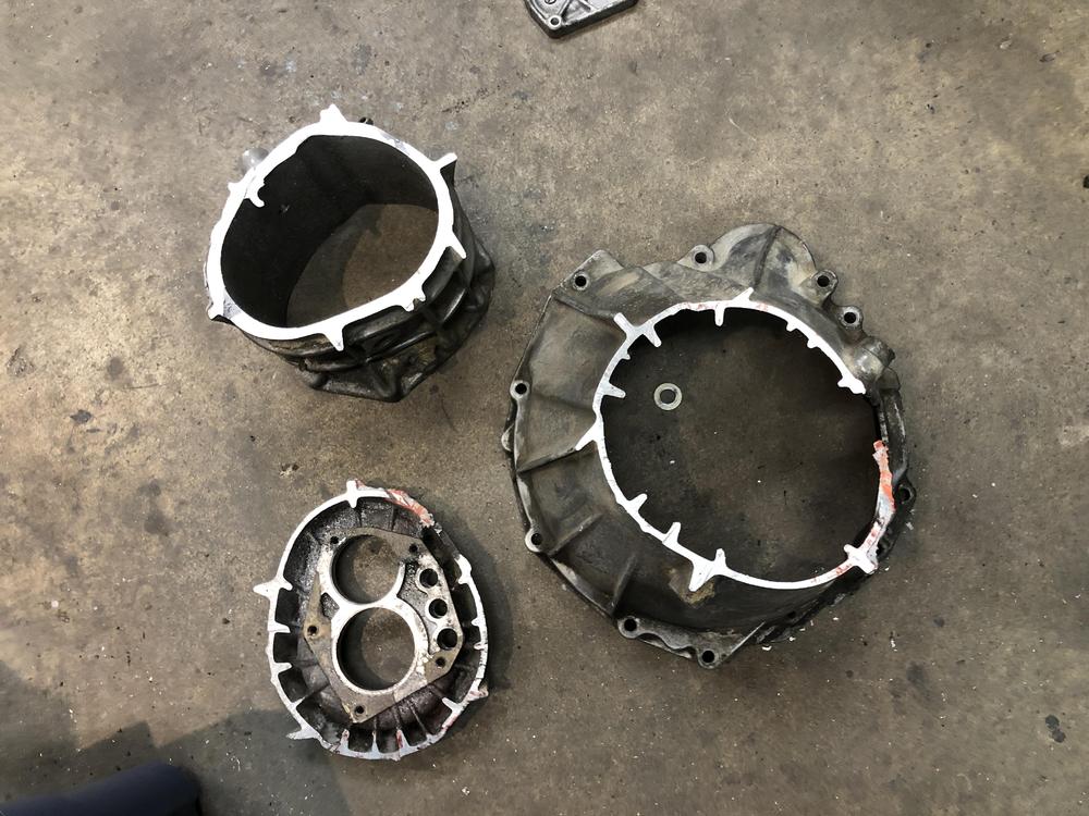


-
FS5W71B Rebuild Thread - Tips tricks and discoveries!
zKars replied to zKars's topic in Engine & Drivetrain
3520DC77-167C-4494-AEC6-329224708A5B.MOV Making it’s first hole and plenty of chips in a piece of scrap. Starting with a 57mm hole. Slowly sneaking up on the correct size by tapping the insert over, then drilling again to enlarge. Test fitting the 62mm bearing at each stage. 3520DC77-167C-4494-AEC6-329224708A5B.MOV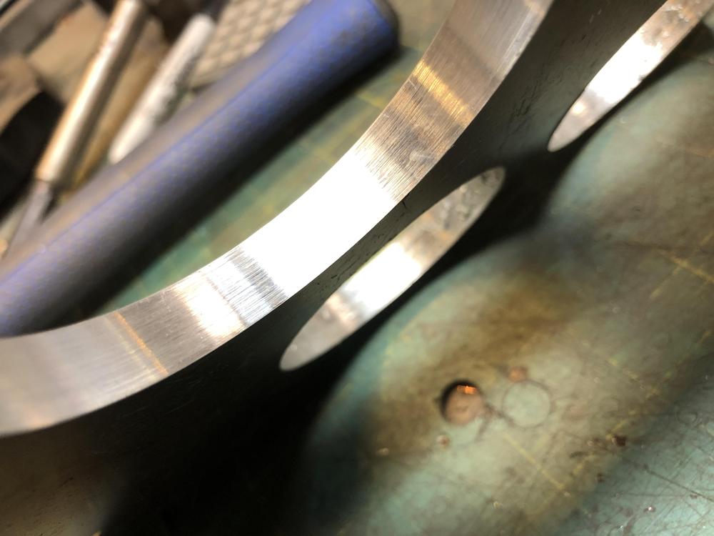

-
FS5W71B Rebuild Thread - Tips tricks and discoveries!
zKars replied to zKars's topic in Engine & Drivetrain
Not yet, I got as far as what you see, then had to leave it. I have to do a proper job of determining the real play, then decide if the bearing inner/outer need to be connected. I’d rather they didn’t, as I don’t want to use drilling torque to overcome friction of spinning that outer bearing race in that tight bore. Even if I have to blow $20 bucks on a new fresh bearing to get minimal play. Adding some grease, ie pretending its a wheel bearing, would also take up some clearance. -
FS5W71B Rebuild Thread - Tips tricks and discoveries!
zKars replied to zKars's topic in Engine & Drivetrain
Progress! Finally got a good tolerance tool done. Now just have to bore the 1/2” hole through the body for the boring bar and start making practice 62mm holes. 6B1A7676-B04D-4E1B-8757-4BF3A2E4E3A2.MOV -
FS5W71B Rebuild Thread - Tips tricks and discoveries!
zKars replied to zKars's topic in Engine & Drivetrain
I had considered this, but a real bearing is the ideal pilot. Nice rounded edges, no guessing about “is it tight or loose enough” and the endless trial and error that incurs. Zed Head I did measure one of the worn dry bearings I have here, and I swear the side to side play is less than 0.001. I’d even consider welding the inside to the outside to remove any play at all. -
FS5W71B Rebuild Thread - Tips tricks and discoveries!
zKars replied to zKars's topic in Engine & Drivetrain
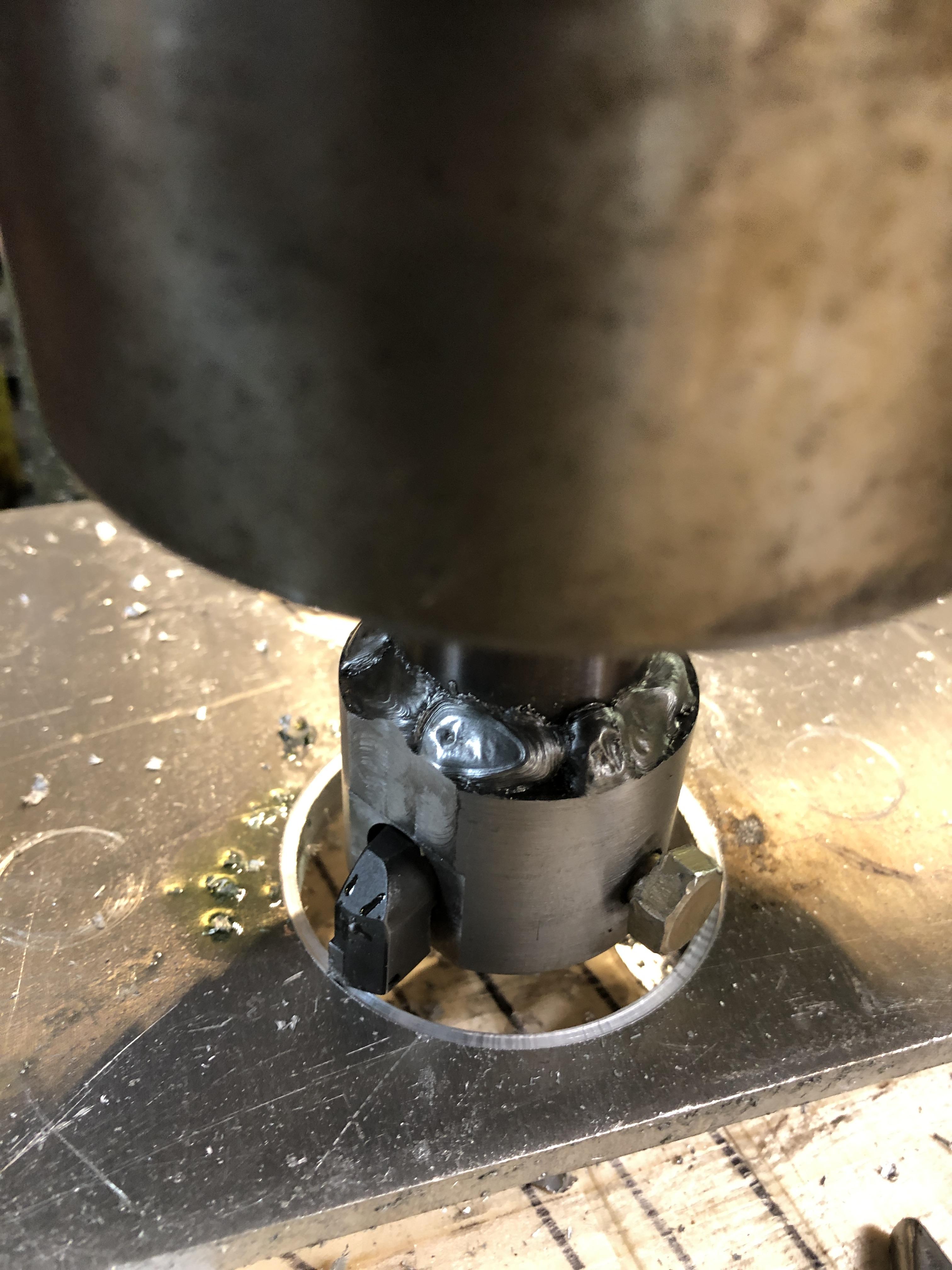
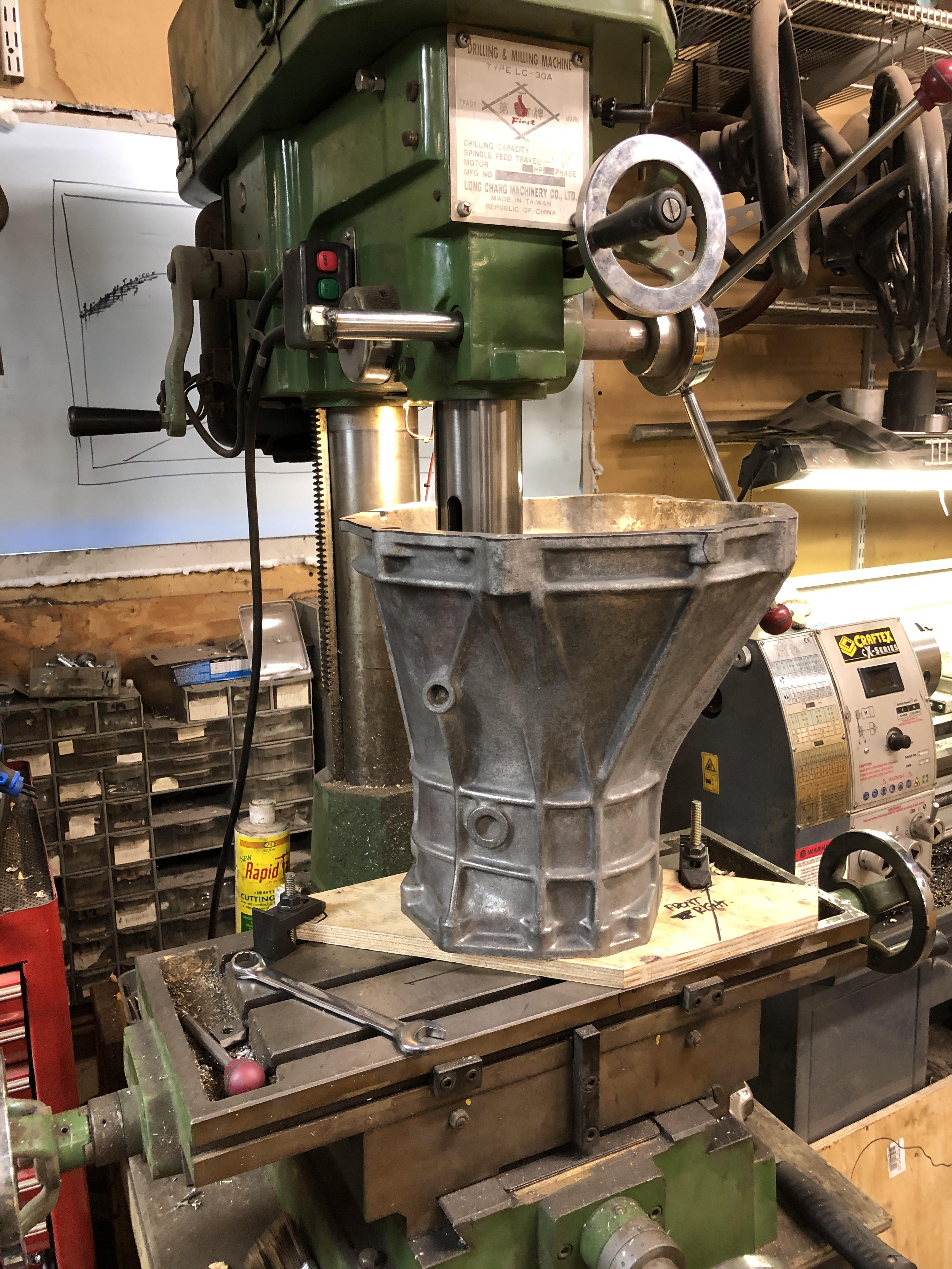
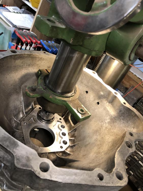
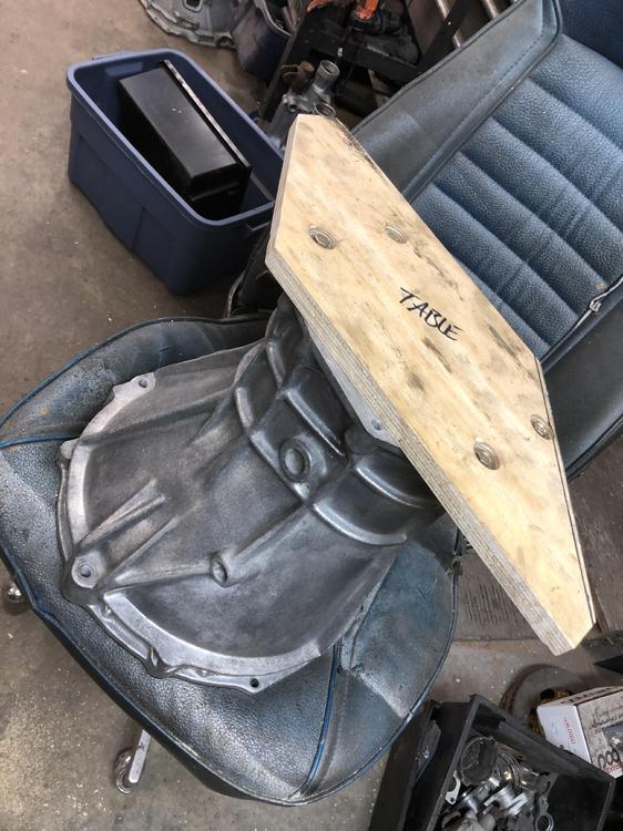
Also worked on the bell housing C conversion bearing 62 mm drilling / centering problem. Progress! It will be possible and likely easy. The idea of using an old 56mm bearing as a pilot is working perfectly. The mill can easily push it through and align the bell housing in 15 seconds. You get the most satisfying woosh/scrapping sound as it gets pushed through and back. Very smooth. I’ll be able to put a 62mm bearing on the bottom of this thing once it’s drilled to 62ish, to test the fit of the bearing. No measuring error, just “Does it press through with the right amount of effort and smoothness” Pretty slick I think. The bell housing is bolted to a piece of 3/4 plywood with four recessed 8mm bolts. The plywood is then anchored to the mill table once it’s centered over the hole. The custom milling head you see is my first attempt. This one is not quite concentric. Practice makes perfect. It is welded to a MT3 mandrel. Fun to align and center. Seems the trick is don’t bother getting it final OD until AFTER the welding is done. Duh... It lacks the horizontal 1/2” hole that will hold the cutter bar. It does have the 56mm bearing nicely sitting on a 22mm boss with am M14 bolt locking it in. The mill head itself has enough clearance to the bell housing sides and plenty of travel. Bit a question about whether it’s worth making one of these or just taking it to a machine shop. Guess it depends on how many I’m going to do. For me in the near future, it makes sense. There is still the issue of needing to machine off a few mm from the OTHER side and make the 1/2 shift rod 16mm. Access from the other side is much tighter obviously. How long a mandrel can I make with a surfacing cutter that won’t wobble....

-
FS5W71B Rebuild Thread - Tips tricks and discoveries!
zKars replied to zKars's topic in Engine & Drivetrain
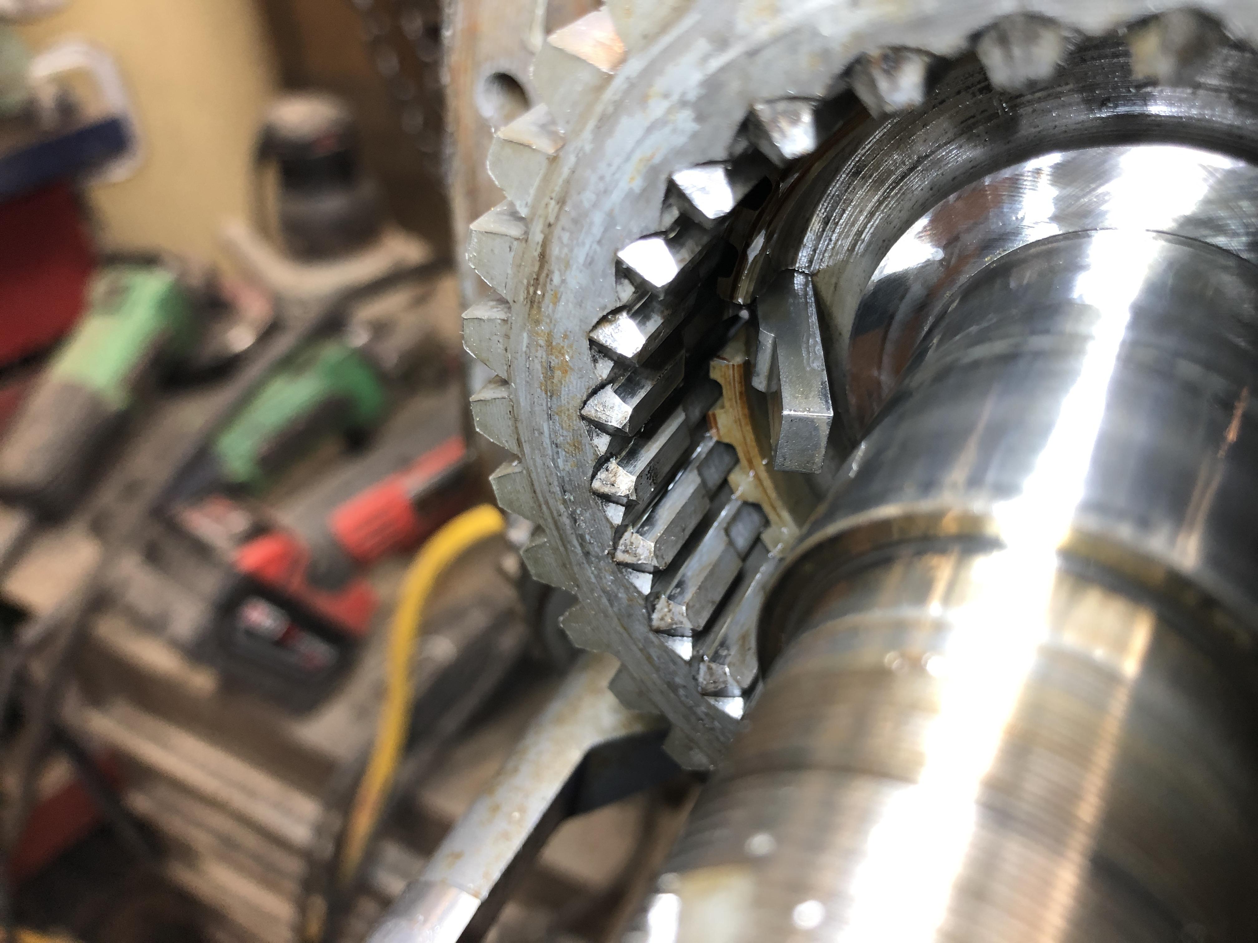
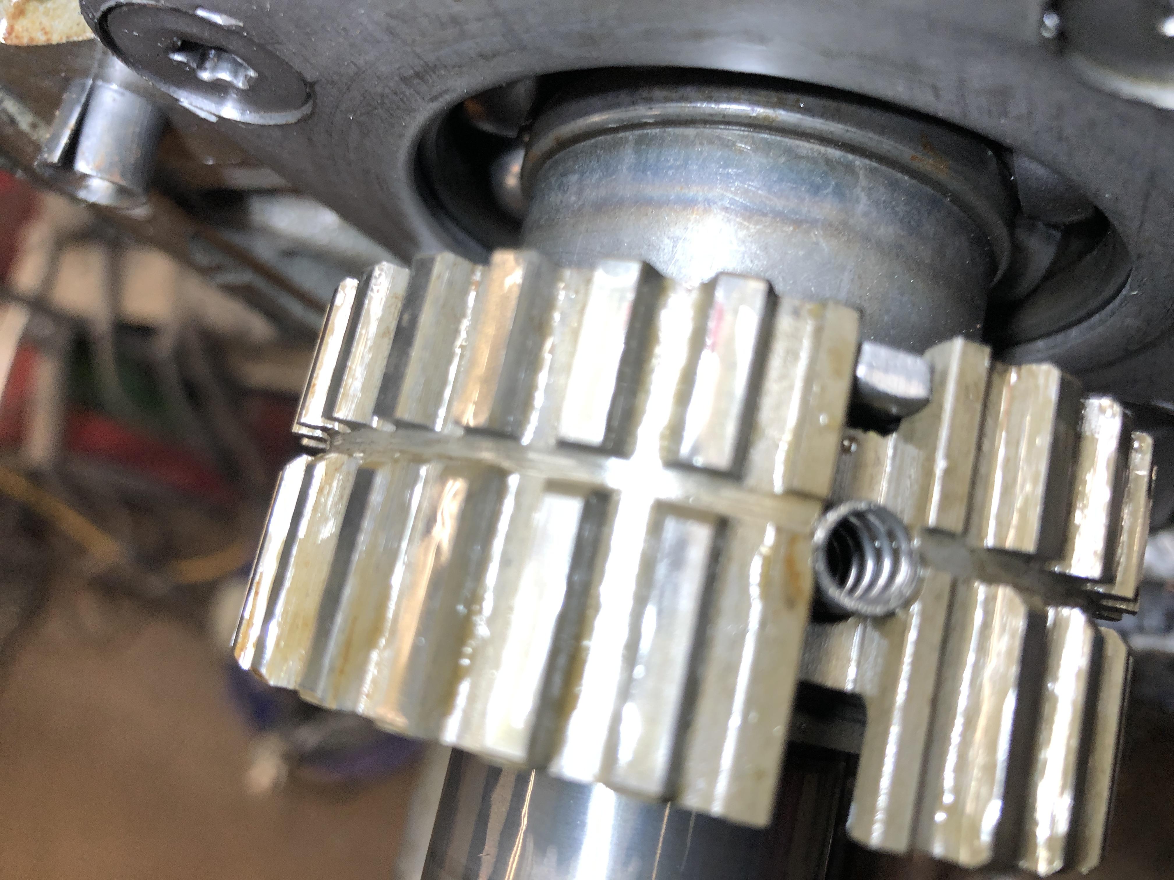
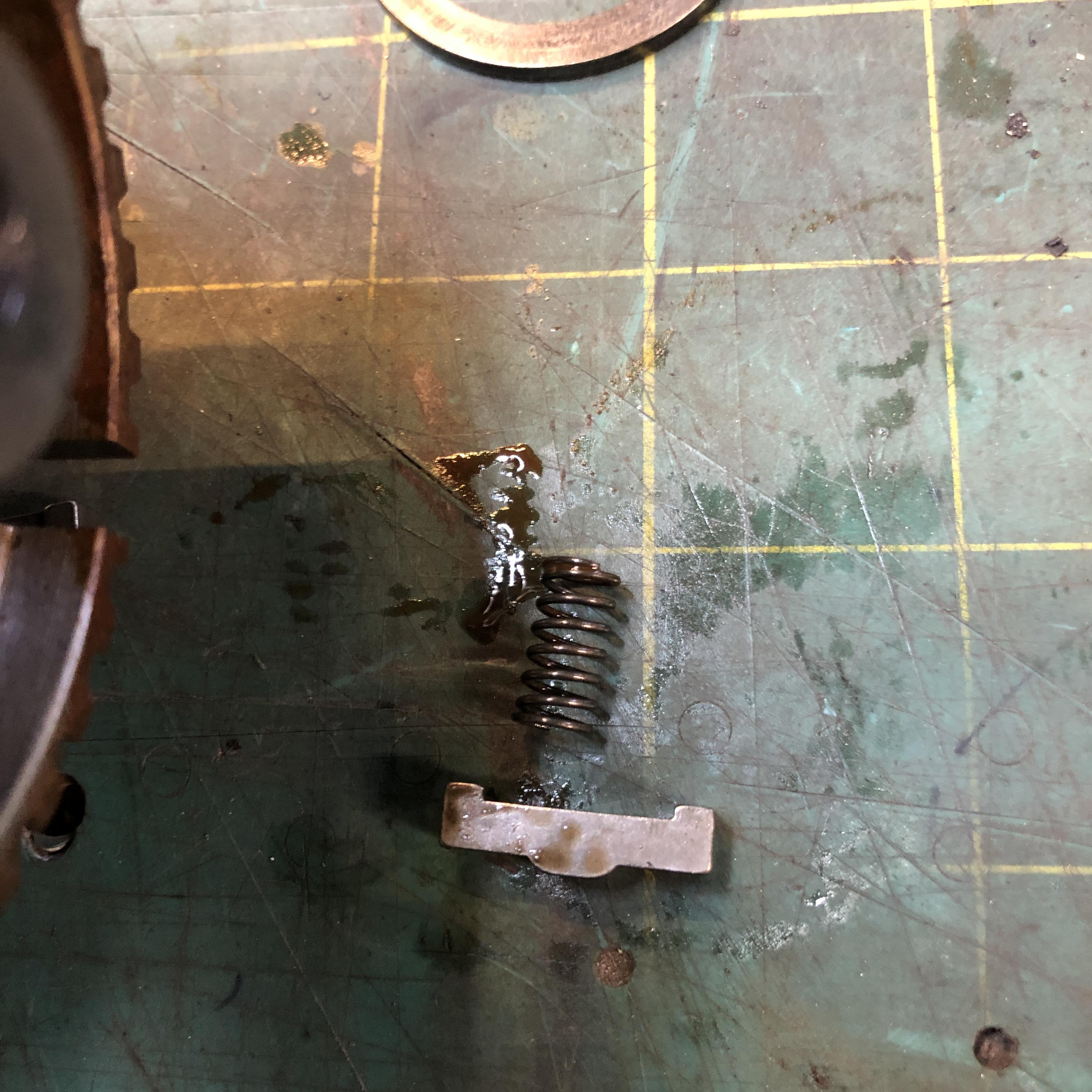
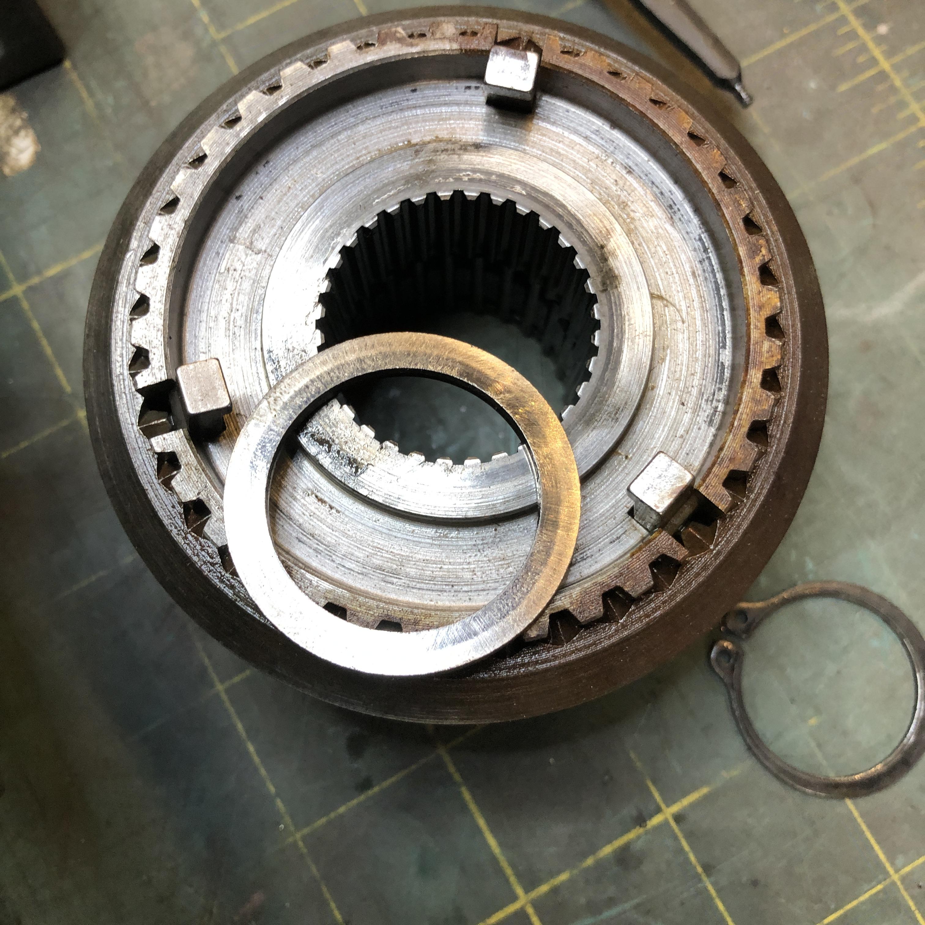
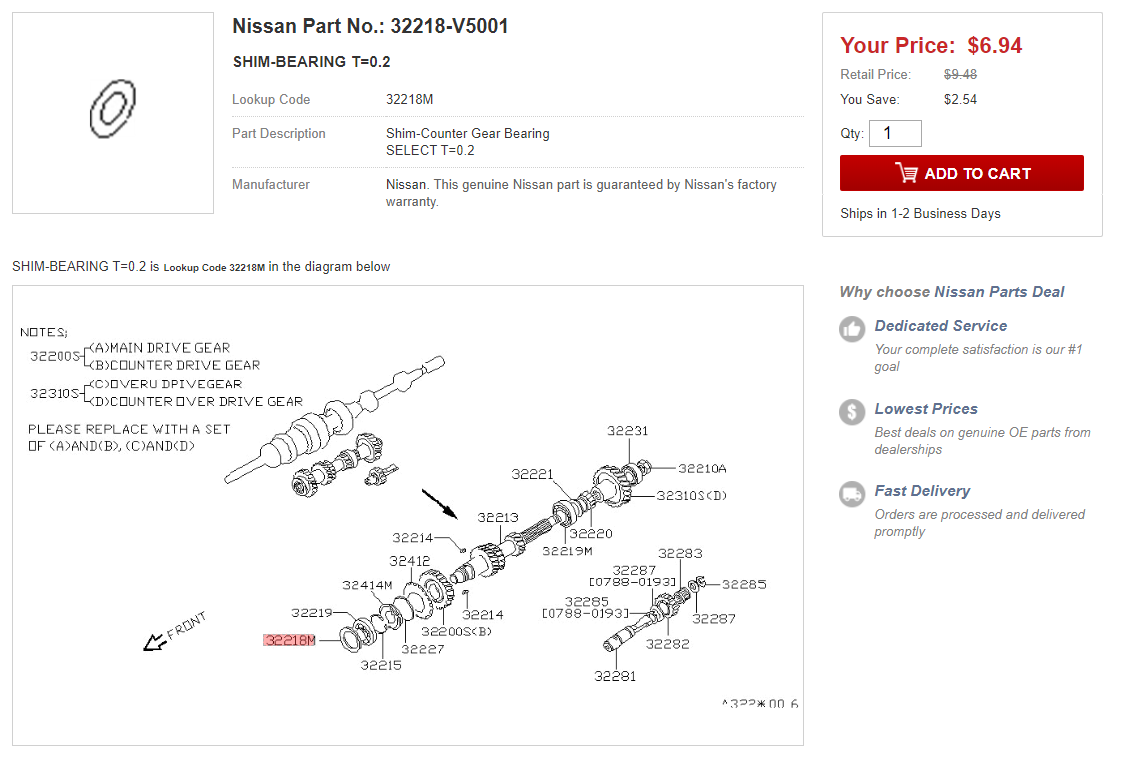
And now that Christmas is over, the real fun begins. First up is something for the "tips" section I guess. Part orientation. The FSM mentions in several sections to ensure part orientation/direction is maintained. They however spend zero time showing you the correct orientation of the parts. So. Let's begin with the 5/reverse synco hub and it's nasty little springs and shifting inserts as they are called. First the syncro hub. It has an offset circumferential groove in the outer teeth, not shown in the FSM pic above. Put the groove more to the front to orient it properly. Front is at the top of the picture, obviously the intermediate plate is there are were are taking pictures of the 5th/reverse parts that are in the rear of that plate. Second, the three little shifting inserts. They have an offset bump on the outer face. Put the bump toward the front. Oh, and bump OUTWARD. The spring touches the flat bottom The FSM shows the three shifting inserts, but the one lower right incorrectly shows the bump to be offset to the REAR. The other two are sort of ambiguous. The bump on each insert is definitely toward the FRONT (left side of the screen grab picture). This picture was taken as I was disassembling the hub. Shows the LONG end of the insert facing toward the camera (rear). Front of the trans is into the picture, so the short end is facing FRONT (can't see it, it's in its groove in the hub) I've confirmed this insert orientation on all the other trans I've taken apart. The other hubs have the same type of inserts but they are symmetrical. Their bump is just like the 5th gear ones, but it's in the center. You can't confuse them with the 5th gear inserts, these have little legs on the back side as well. Here in the picture they are shown with their mating springs in the correct orientation, with the bottom of the picture being outward.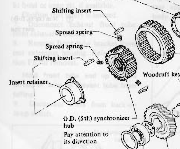


-
FS5W71B Rebuild Thread - Tips tricks and discoveries!
zKars replied to zKars's topic in Engine & Drivetrain
And while I'm thinking about it.... I mentioned earlier about the possible wisdom of put the 62mm front counter shaft bearing in your FS5W71B transmission. I must mention that it will then require two additional items other than the bearing. The front cover plate for the C trans must be used as the recess in the back is sized for the larger bearing. It ain't cheap either. $99 from https://www.transmissionpartsdistributors.com/fs5w71-series-transmission-front-bearing-retainer-original-equipment-fits-nissan-84-4-cyl-cars-trucks/ This also means you will need a bearing shim for the C trans as well. Different thicknesses are available. There is also a tiny detail about the C bearing being 17mm thick vs the B bearing being 16mm thick. Some case material may have to be removed around the bearing just like you do with a full C type conversion, maybe somewhat less.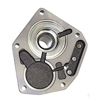

-
 I’m sure I can find a couple. PM me.
 -
I see there are two kinds. One with a plain silver disc and one with fan blades on silver part, slightly larger overall diameter. ME thinks the smaller one is the 73? 260 and up had a slider switch. Surely we discussed this before here.