ea6driver
-
Posts
185 -
Joined
-
Last visited
-
Days Won
3
Content Type
Profiles
Knowledge Base
Zcar Wiki
Forums
Gallery
Events
Downloads
Store
Blogs
Collections
Classifieds
Everything posted by ea6driver
-
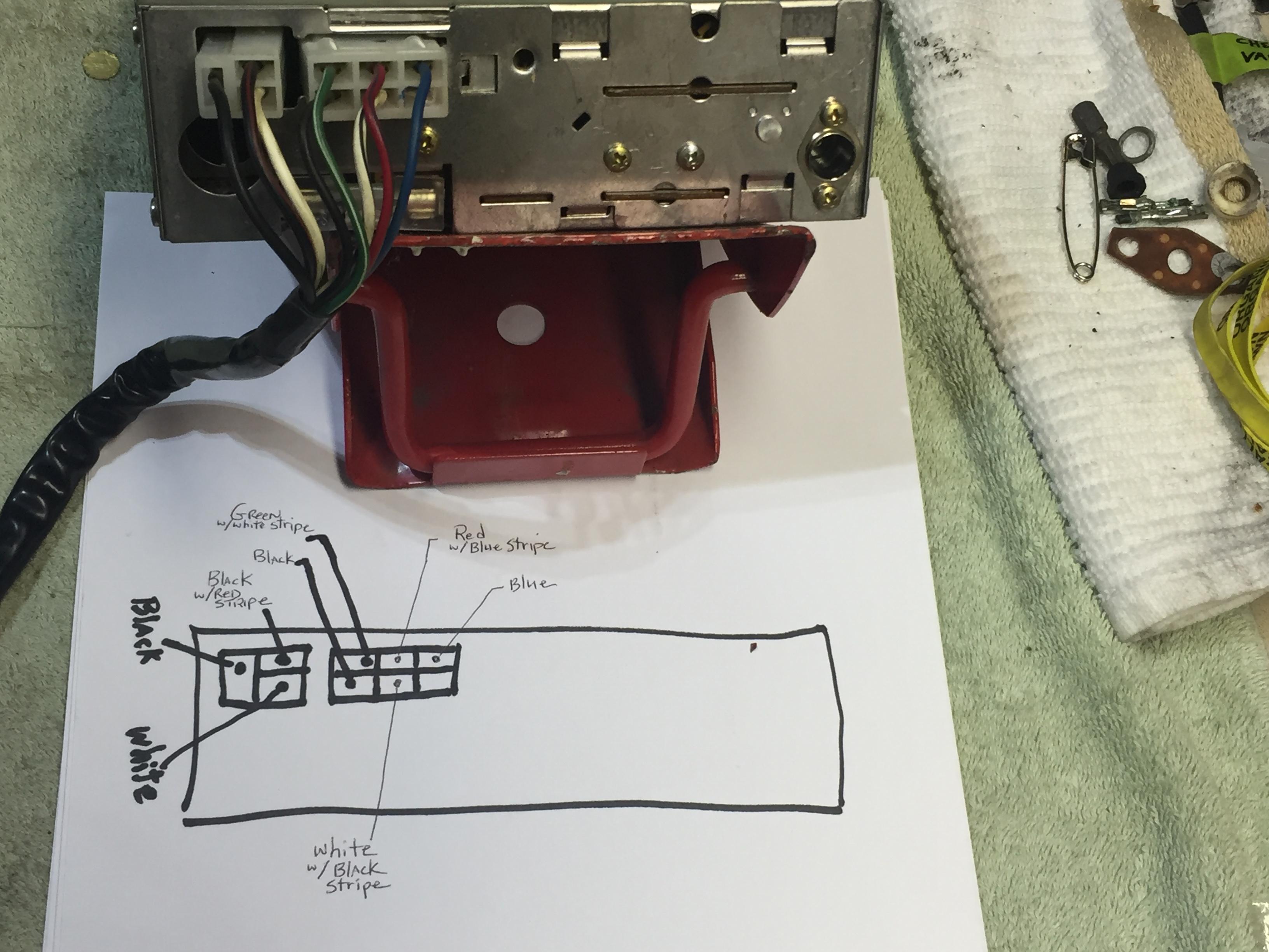
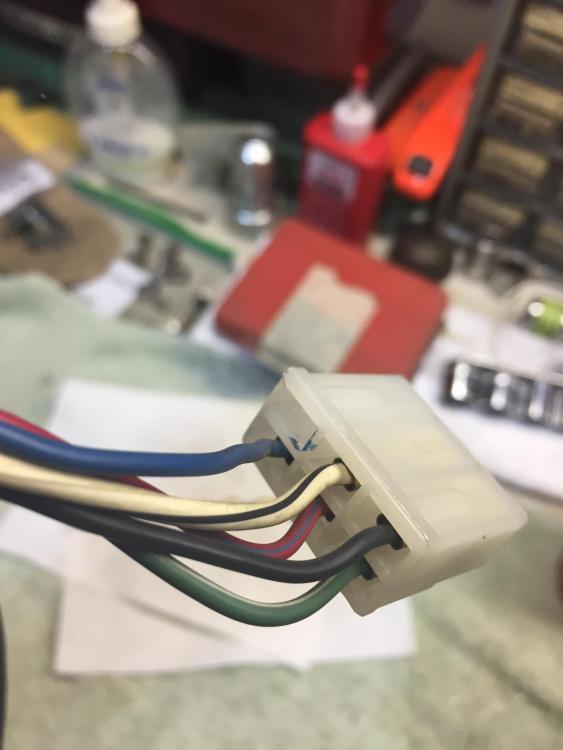
Here's a photo that shows specifically which color wires connect to each of the "spades" in the back of the radio. Note that on the 6 pin connector that the lower right position is unused...at least in the hitachi radio in the 78 year model Z. So there are 8 wires that connect into the radio. The other end of the "sub harness" has the wires grouped together differently...I'll post a photo of that end of the sub harness below...

-
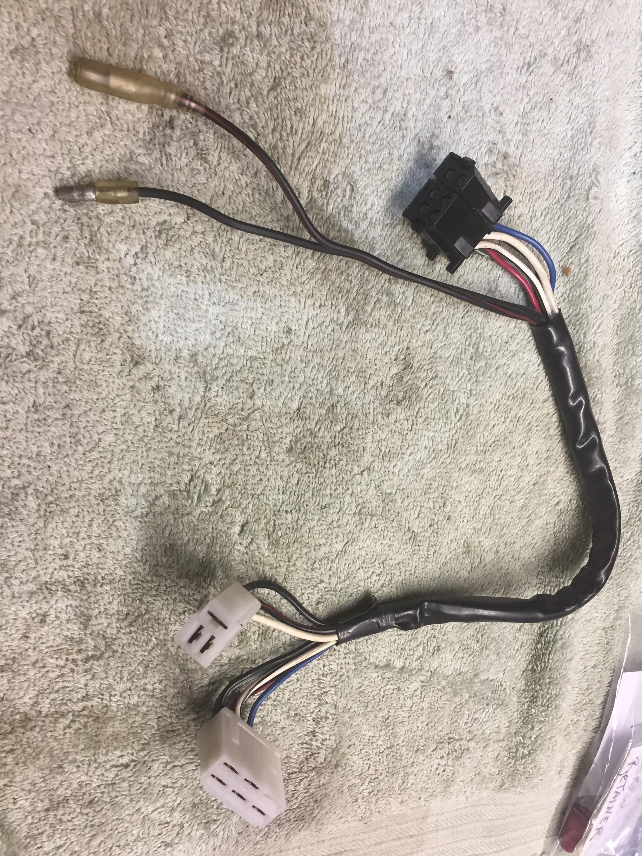
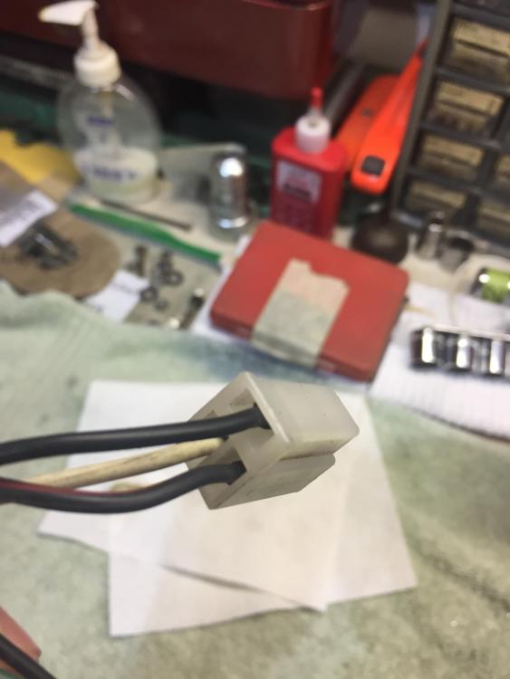
The 3 pin molex is not for the power antenna...the power antenna is a completely separate connection that extends directly from the power antenna switch (mounted to the right side of the radio in the 78 year model) to the main console/dash harness. However, that separate antenna molex connector is very similar (if not exact) to the 3 pin molex connector that plugs directly into the back of the radio.
-
Thats a photo of the complete "sub harness" that connects the radio to the main console harness
-
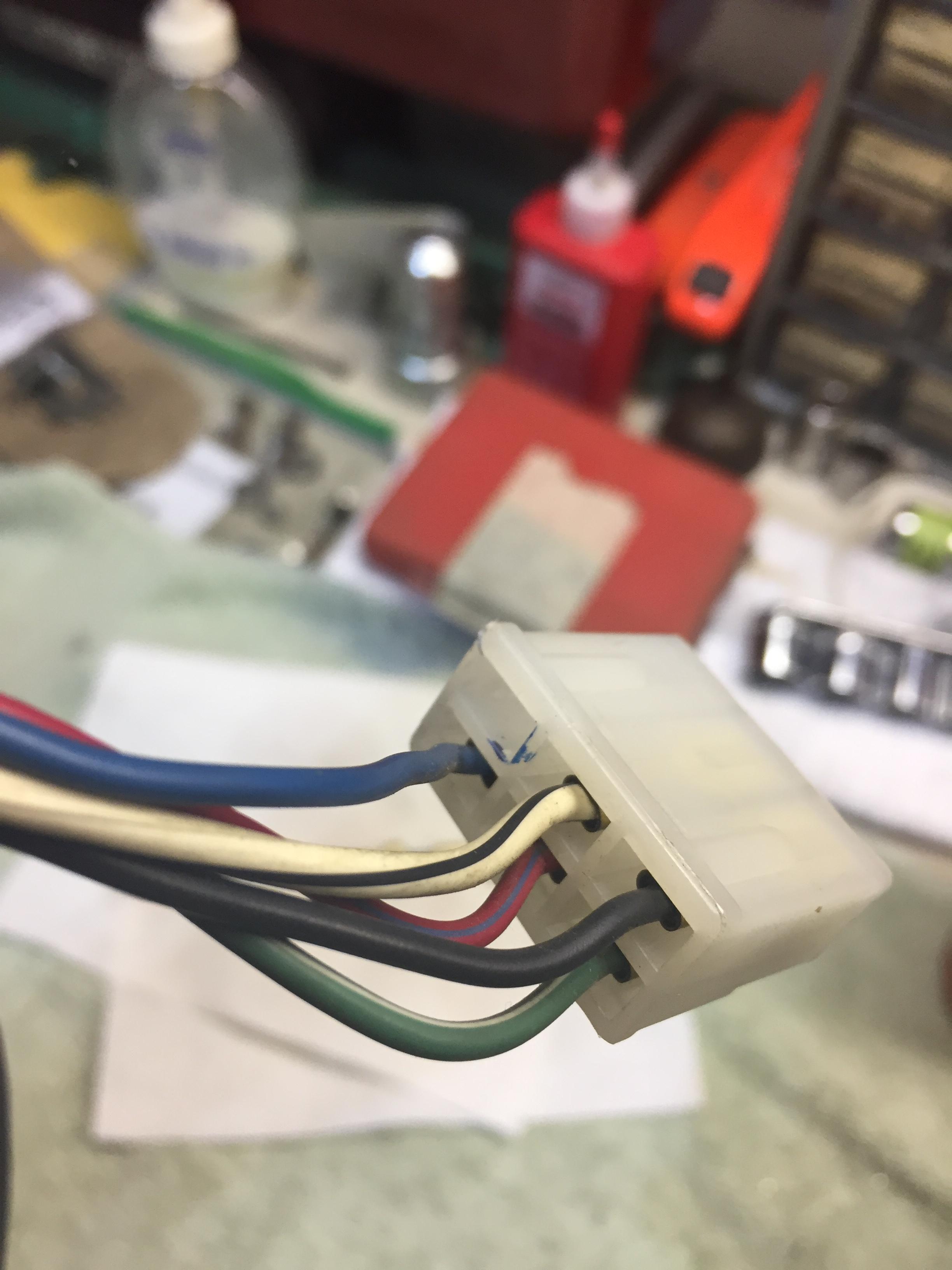
Also, as you can see from the photos, the 6 pin connector only uses 5 of the 6 wire positions
-
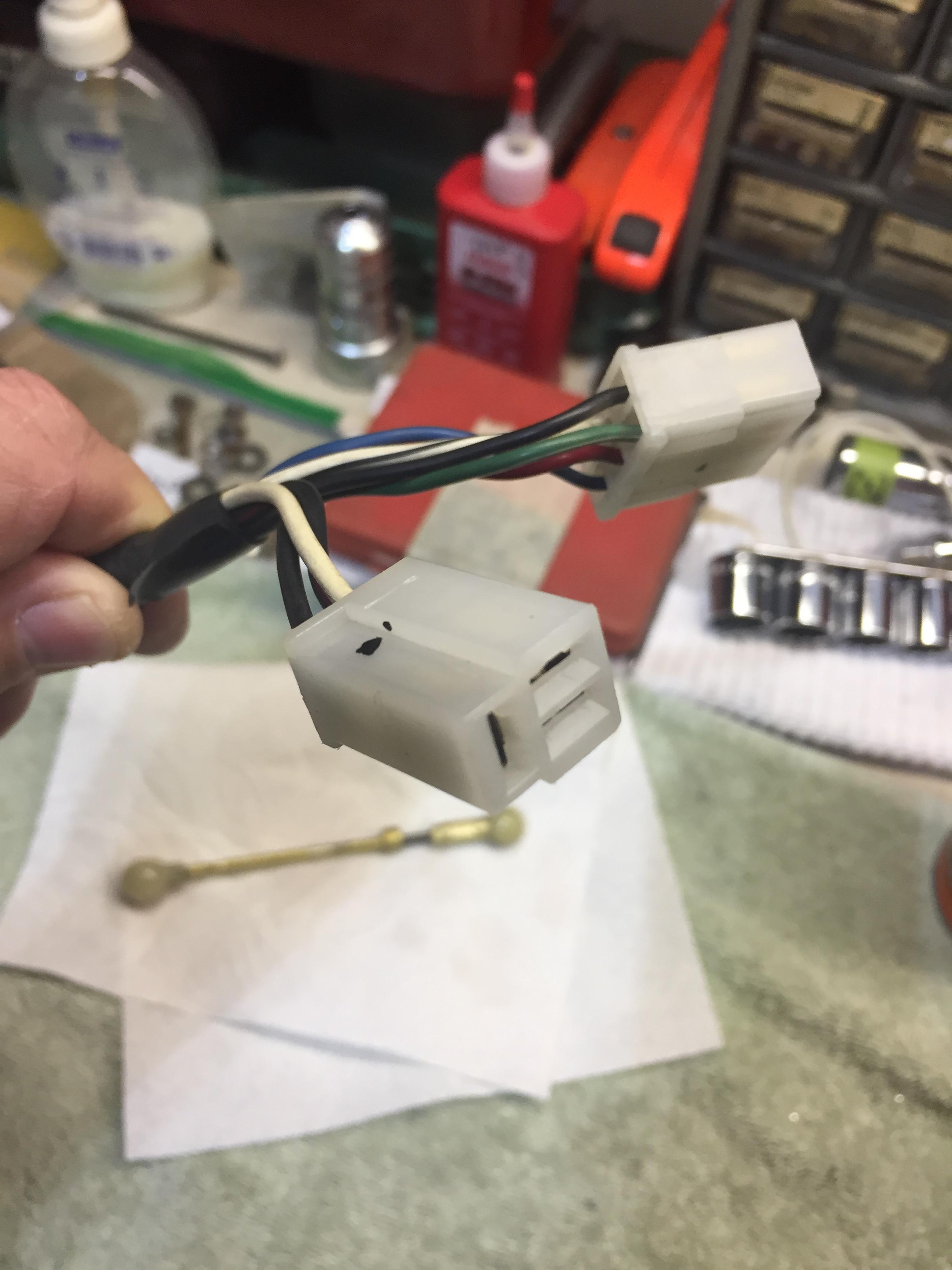
These photos show which color wires from the sub harness I mentioned above connect into the 3 and 6 pin connections in the back of the radio....is this what you need?


-
yes....it's a Hitachi KMS-2411z (make and model number)...still looking for the photos that might help you
-
My 78Z has the original radio and doesn't use the 5 pin DIN connection. It does use both the 3 and 6 pin "molex" connections. My radio model is a KMS-2411Z. The original set up uses a "sub harness" that connects the radio to the main console harness. These sub harnesses can be hard to find since many owners simply discarded them when they installed aftermarket sound systems. Give me a little while and I think i can come of with a few photos of the set up showing the wiring scheme.
-
One day later.... So I spent the afternoon trying to figure out this problem. After checking all the basic connections, I finally decided to start disassembling the components to check them out individually. The first component to come out was the brake master cylinder. Upon disconnecting the two brake lines from the bottom of the master cylinder, I immediately noticed that the brake lines were blocked/plugged up with the remnants of paper towel. Apparently, in my haste to reassemble everything I forgot to remove all of the paper towel pieces that I had used to plug up the lines/ports while everything was apart. After a few hours of blowing out lines with compressed air and taking apart the master cylinder I'm pretty sure that I've now successfully removed all the offending material. I feel like Homer Simpson....DOH!!!! A self imposed headache for sure. My wife said that I shouldn't confess to this mistake on the forum...but I felt obligated to disclose what the solution was to the problem that I originally posted...maybe it will help someone else out sometime down the line... I'm feeling confident that tomorrow the brake bleeding job will go much easier!
-
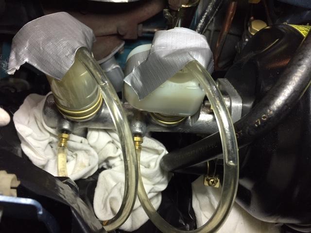
78 280Z Background....about a year ago I completely disassembled everything in my engine bay so I could repaint the bay, refurbish all the engine compartment components and then reinstall it all. I'm finished up with it all now...the last remaining task before getting the Z back on the road is bleeding all four brakes. Video Player is loading. Play Video Play Unmute Current Time 0:06 / Duration 0:19 Loaded: 100.00% Stream Type LIVE Seek to live, currently playing liveLIVE Remaining Time -0:13 Playback Rate 1x Chapters Chapters Descriptions descriptions off, selected Captions captions off, selected Audio Track Fullscreen This is a modal window. Beginning of dialog window. Escape will cancel and close the window. Text ColorWhite Black Red Green Blue Yellow Magenta CyanTransparencyOpaque Semi-Transparent Background ColorBlack White Red Green Blue Yellow Magenta CyanTransparencyOpaque Semi-Transparent Transparent Window ColorBlack White Red Green Blue Yellow Magenta CyanTransparencyTransparent Semi-Transparent Opaque Font Size 50% 75% 100% 125% 150% 175% 200% 300% 400% Text Edge Style None Raised Depressed Uniform Dropshadow Font Family Proportional Sans-Serif Monospace Sans-Serif Proportional Serif Monospace Serif Casual Script Small Caps Reset restore all settings to the default valuesDone Close Modal Dialog End of dialog window. Advertisement So today I jacked up the rear, removed the wheels and started the process by trying to bleed the left rear brake. Video Player is loading. Play Video Play Unmute Current Time 0:00 / Duration 0:19 Loaded: 100.00% Stream Type LIVE Seek to live, currently playing liveLIVE Remaining Time -0:19 Playback Rate 1x Chapters Chapters Descriptions descriptions off, selected Captions captions off, selected Audio Track Fullscreen This is a modal window. Beginning of dialog window. Escape will cancel and close the window. Text ColorWhite Black Red Green Blue Yellow Magenta CyanTransparencyOpaque Semi-Transparent Background ColorBlack White Red Green Blue Yellow Magenta CyanTransparencyOpaque Semi-Transparent Transparent Window ColorBlack White Red Green Blue Yellow Magenta CyanTransparencyTransparent Semi-Transparent Opaque Font Size 50% 75% 100% 125% 150% 175% 200% 300% 400% Text Edge Style None Raised Depressed Uniform Dropshadow Font Family Proportional Sans-Serif Monospace Sans-Serif Proportional Serif Monospace Serif Casual Script Small Caps Reset restore all settings to the default valuesDone Close Modal Dialog End of dialog window. Advertisement As an aside, before I started this "refurbish" process, the brakes were working perfectly...very firm, even braking from all four brakes. Using a Motive Products Power Bleeder, pressurized to 15 psi, I was unable to get a steady flow of brake fluid from either rear brake bleeder port. Additionally, when I tried pushing the brake pedal it was very firm...as in I could barely push it down at all. Next I connected clear tubes to both of the master cylinder bleeder ports an stuck the other end of the tubes into the reservoir (see photo). I opened the bleeder screws and was easily able to pump the brake pedal, circulating brake fluid from the bleeder into the reservoirs. So, the question is, why is the brake pedal so firm with the master cylinder bleeder screws closed, but not with the bleeder screws open? I'm thinking 1) the brake master is malfunctioning 2) there is some kind of blockage preventing brake fluid from flowing freely from the master cylinder to the rear brakes...perhaps a problem with the NP valve (proportioning valve). Eager to hear your ideas.
-
Wow! Thank you for that not so obvious Z emissions systems lesson Captain Obvious! I always try to do some research before posting a question on the forum, but I admit, there wasn't a chance I was gonna discover that answer. I'm just glad you didn't find that diagram in the 78Z FSM! Until your response this morning I didn't think we were gonna get a likely answer to this orifice mystery...My hat's off to you sir!
-
Yeah...after blowing and sucking on both ends...it seems like it's just a "restrictor" because I encountered the same amount of resistance no matter what....either that or, if it is some kind of check valve, then it's broken.
-
It's a 78. I purchased it in 1980 from the original owner so I'm pretty sure it's the original factory hose. Thanks for that insight.
-
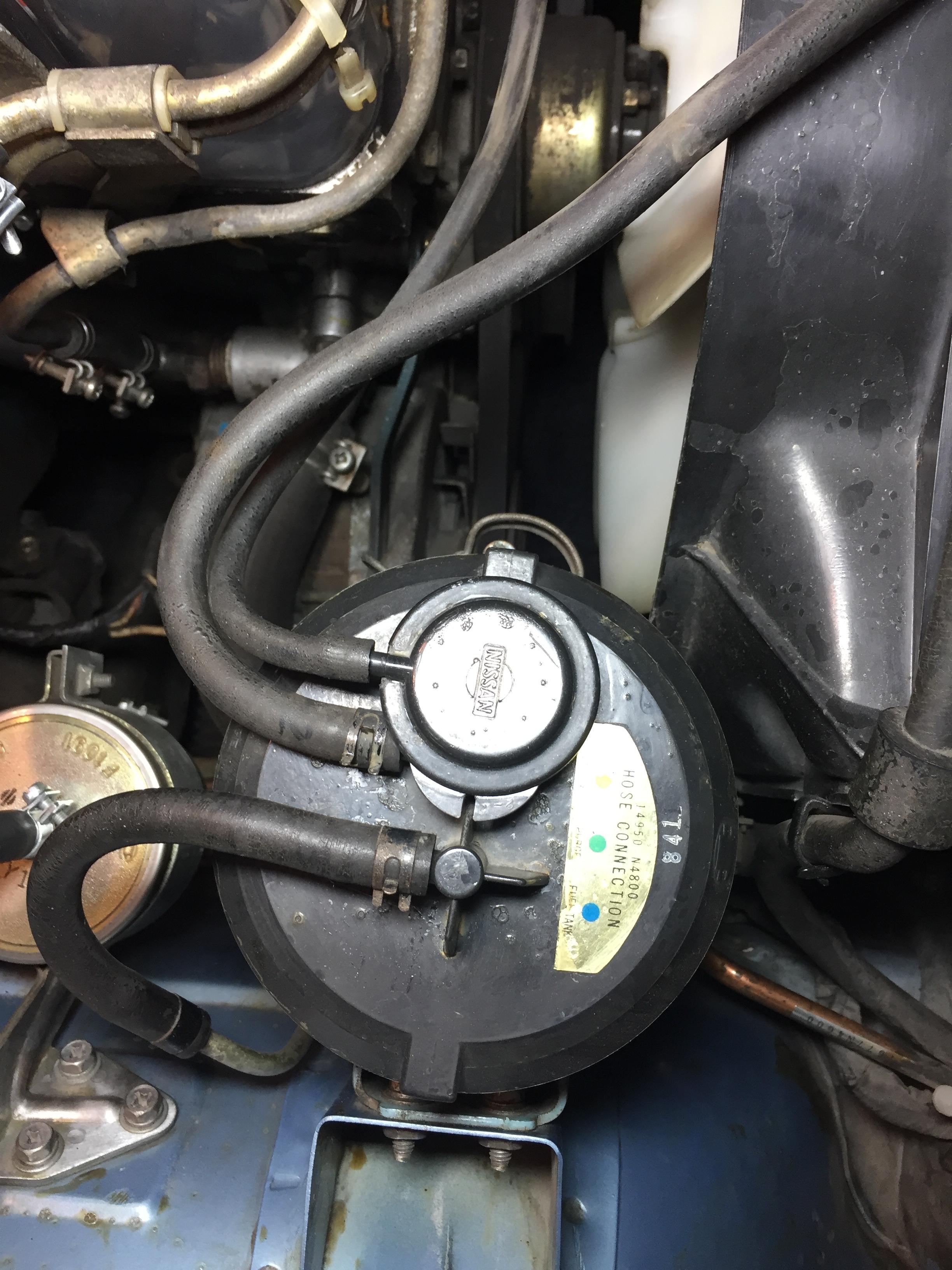
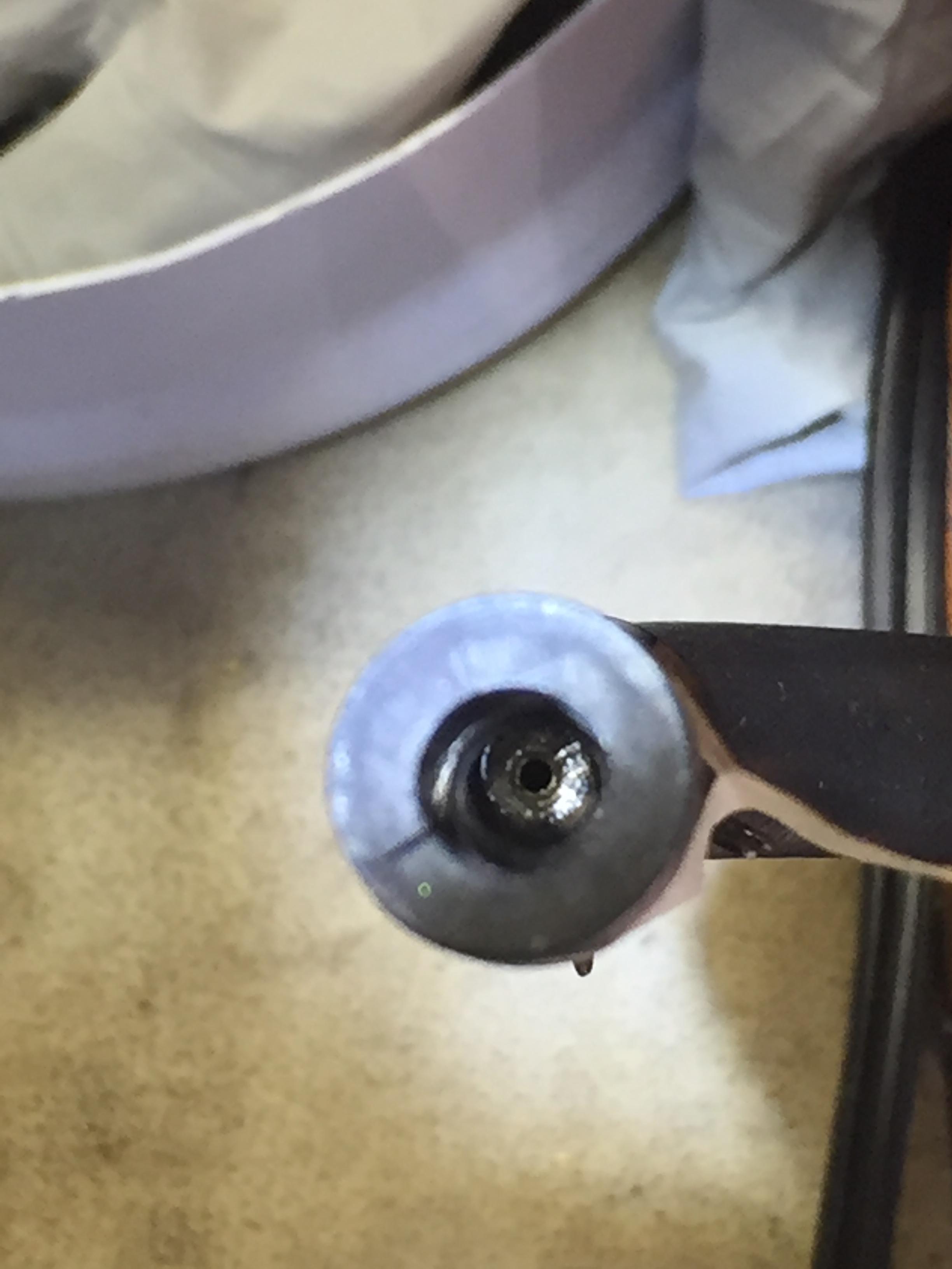
I was reinstalling all the hoses leading to/from my carbon vapor canister today and I noticed something interesting. The short hose that connects to the steel line leading back to the fuel tank isn't simply a rubber hose. In the attached photo, i'm referring to the rubber hose connected to the canister port labelled by a blue dot (Fuel Tank). As I was about to reinstall it I thought I'd blow into it just to make sure that it wasn't clogged and, surprisingly, I felt resistance that seemed like a clog. Upon further investigation, I discovered that there is an obstruction in the hose that seems purposeful. This obstruction seems to be metallic and has a small hole through the center of it (see photo of hose end). I couldn't find any reference as to the purpose of this hose restriction anywhere. Could anyone shed some light on exactly what this is? What is it called? What is its purpose? Sorry if Fuel Injection isn't the best place to post this question...It was either here or Engine/Drivetrain. Thanks!


-
Hi Dmuzial, I have a 78Z manual, and had this same problem about a year and a half ago....actually started a thread in the Engine and Drivetrain section since I originally ran across the problem when installing the diff...you can see it here: Lots of good responses to my questions by the forum members. Bottom line was that some of the drawings in the FSM were copied from previous year models and are incorrect. Like you, I initially installed the bar with the bushing cylinders aft of the mustache bar (per the FSM diagram) only to discover that I couldn't get the forward diff mount to line up correctly. It all worked out good once I reversed the bar so that the bushing cylinders were forward. Love this forum...never fails to get you back on track with whatever Z problem you're tackling at the moment!
-
Thank you for that addition to this puzzle. So...it seems as if that collar was installed the same way on both yours and mine. Perhaps we have a trend going here. I don't understand the reasoning behind this installation option, but, unless I hear differently from another member, I will likely go with this option!
-
Hmmm...hadn't thought about that. Hoping another forum member can shed some additional light on this....Cause we now have 3 possible installation possibilities for this mysterious little metal collar!
-
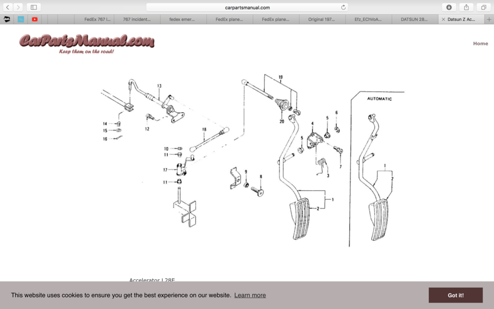
Here's the diagram for the '78...unfortunately it doesn't show the little metal collar either...
-
Very interesting...that parts diagram says it's applicable up to Nov '74.....mine is a 78 and it does appear that there are differences...I'm going to try and find a similar parts diagram for the 78 year model and see if that definitively answers the question. Thank you.
-
KMS 2411Z...at least that's the model number my 78Z had installed original from the factory.
-
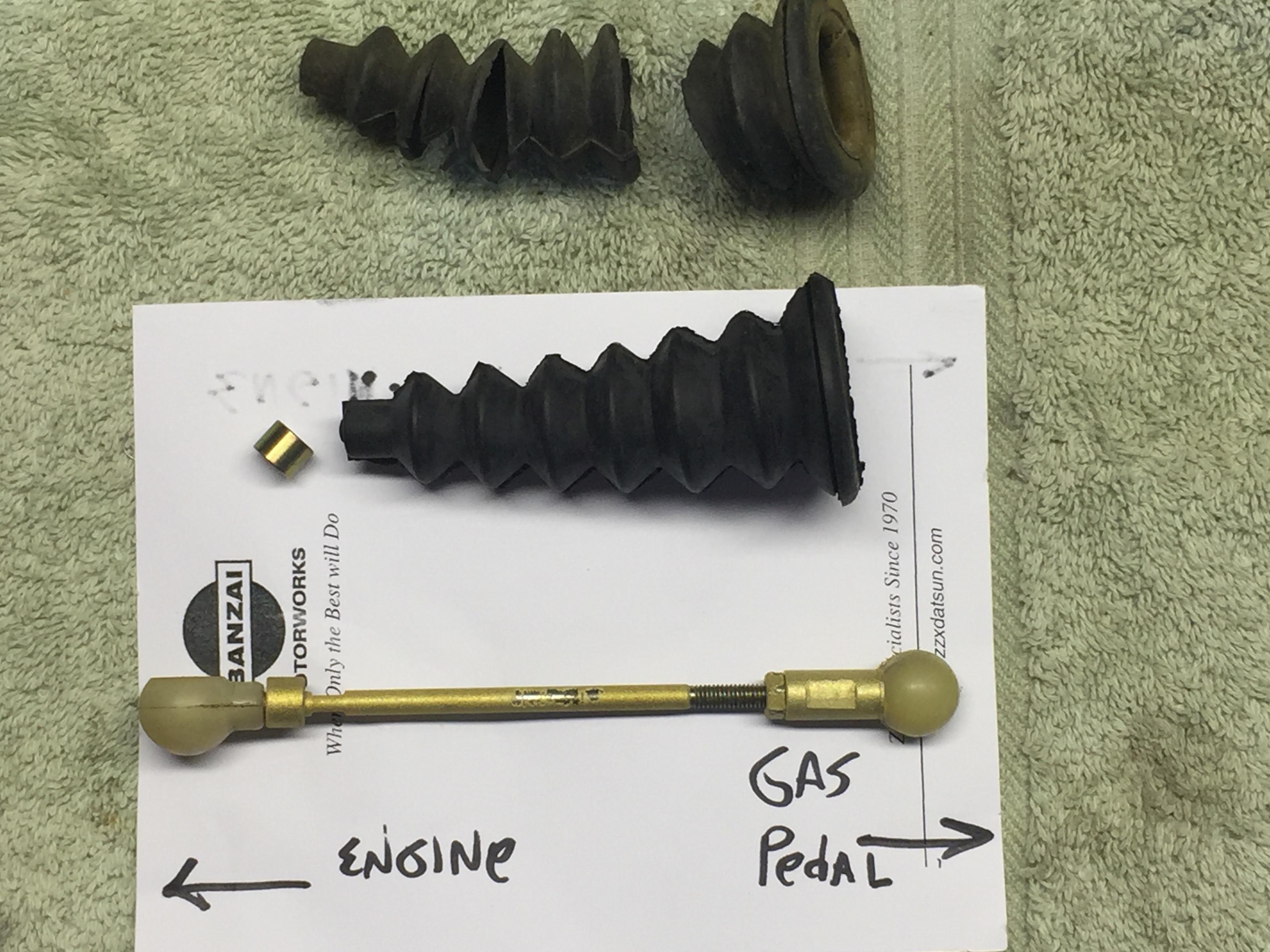
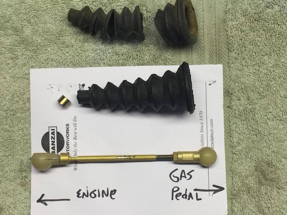
No...look at the first picture I posted above. In the photo you can see the new rubber boot, and just to the left of it you can see a small metal "collar" that slips over the shaft/shank after removing the plastic ball piece. That is a replacement collar that came with the replacement rubber boot. Also, below that, you can see the original "collar" on the shaft as it was removed from the car. This collar fits loosely over the shaft/shank and can easily slide up/down the shaft. During installation, the collar can either be positioned outside the boot (so that it sits next to the plastic ball) or inside the boot. The small end of the boot looks like it was designed so that the small metal collar would fit perfectly inside the end of it. I was unsure which installation option is correct. Hope this makes sense.
-
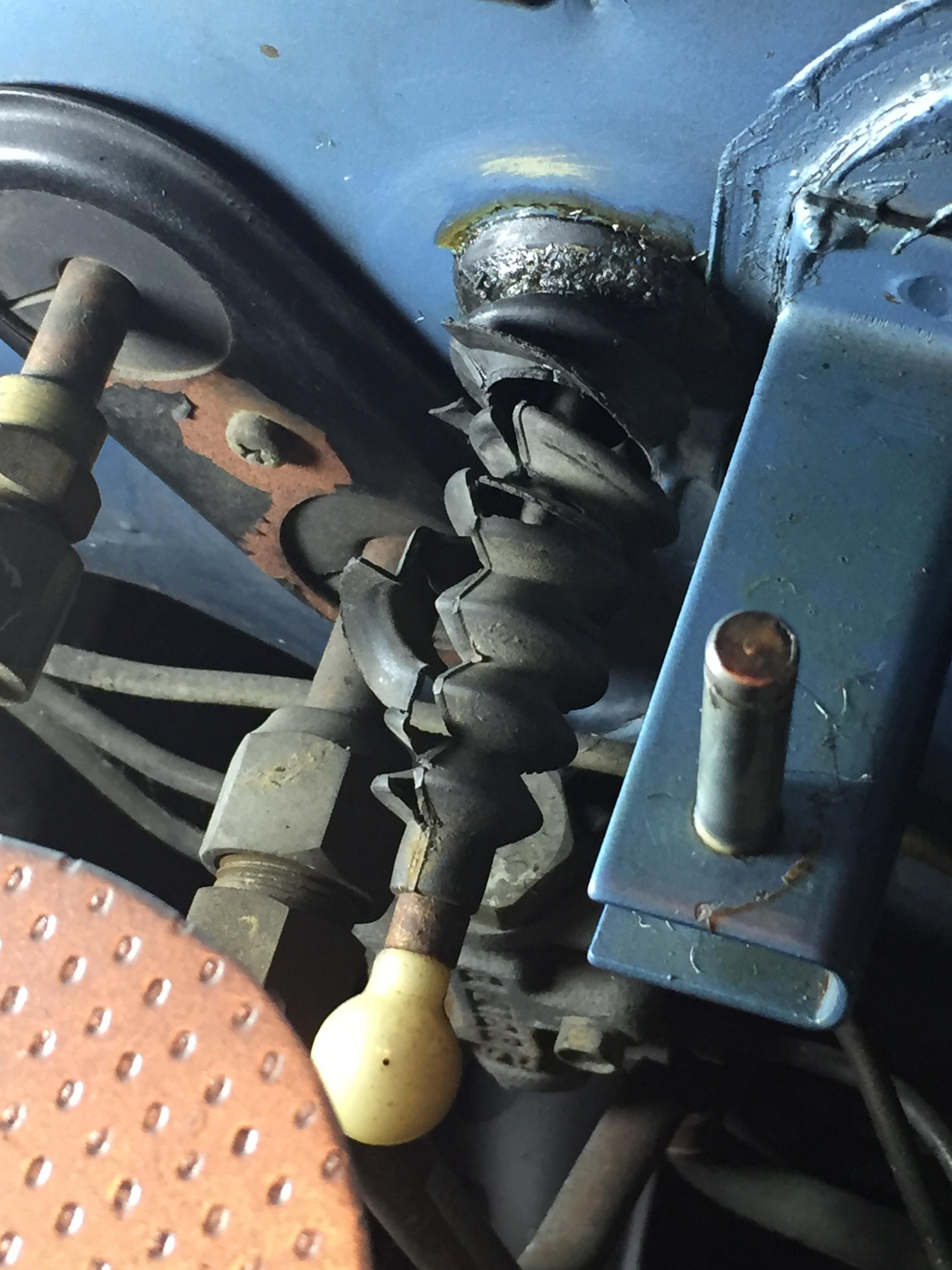
And the little metal collar? Here's a pic I took before disassembling everything...in this pic it looks like that metal collar is positioned between the ball joint and the rubber boot...but the shape of the small end of the rubber boot would suggest that the metal collar is supposed to be inside the rubber boot. Given the age of the car and the possibility that this linkage was previously disassembled sometime in the past, I'm not convinced that the collar's position in the pic is necessarily accurate. Thanks!

-
Two questions...1) How do I install this new/replacement accelerator rubber boot onto the linkage without breaking it? And 2) does the metal "collar" that is on the shaft go inside the boot or outside the boot? As you can see there is an adjusting nut at the gas pedal end of the shaft, but I've tried to loosen it without success...was afraid if I kept wrenching on it something was going to break...Also, both ends with the "cups" are plastic, and I'm sure quite brittle and unforgiving at this stage in their lives. It looks like clearly I need to remove one "cup" end to get the boot on because the small end of the rubber boot doesn't look like there is any way for it to stretch over the cups. Do the "cups" screw off? Or are they simply pressed on? I figured surely one of you has tackled this job before and can give me some good advice here. Thanks!
-
Thanks! I was kinda thinking about opening up the case to investigate the cause of the problem...I mean, what do i have to lose? Is this something that can be easily purchased and replaced by a motivated amateur z clock repair man?
-
So I hooked up the clock to my 12V car battery as described above...and sure enough, the clock seemed to operate normally, at least for a while. Every time the minute hand would rotate around to approximately the six o'clock position it would "stick" in position. I could adjust the minute hand using the center "set" knob, and it would begin operation normally again...at least until it rotated around to that same position again. It felt as if there was something slightly obstructing the minute hand at that position of its travel. Anyway, the point being that there appeared to be no problem powering the clock up by connecting it directly to the car battery.