JimmyZ
Free Member
-
Joined
-
Last visited
Everything posted by JimmyZ
-
 Like moonpup said the belts should be able to snake around the fan blades. That's how I've always done it. The only reason I can see to remove the blades is if adjusting the other belts is too much of a pain with the fan in the way. As mentioned above the four nut WP pulley removal is way easier than taking the fan off the clutch if you really need to. My2c Jim
 -
Drilling through high strength bolts is next to impossible. A carbide drill bit in a milling machine might get it. Ease of removal really depends on where the bolt sheared at. (Above, at or below the surface) Any drilling on something like this should be done in a machine and not by hand so as to avoid skipping and damaging the threads. The cam tower mating surface must not be marred unless you want to have the top of the head milled. I just had a head bolt snap in an L24 block. Fortunately it had enough protrusion to allow me to weld a head on it. This welding apporach was a last resort because the bolt had begun to fracture. It came off easily once the head was welded on. The heat helped to break the Loctite/rust bond. In aluminum removing bolts is much easier. In your case heating the head will help during removal. If the wife agrees clean the head and bake it in the oven for an hour at 350-400. Wrap the head in aluminum foil to keep everything you cook from being cylinder head flavored. Place it on something clean and flat so that the head surface isn't damaged. (Cookie sheet) The aluminum will be softer and easier to scratch when it's hot. Take a drift or punch and tap the edge of the bolt to loosen it. Work fast while the aluminum is hot. Little taps are all that's needed. If this doesn't get it then EDM (electrical discharge machining) can. Of course it would be easiest to drop it by a head shop and let them take it out.
-
Apologiesin advance. I just read the above posts and found that you were really talking about the small phillips. (Post below is about stubborn hose clamps) Regarding the valve screws... I had to use Vise grips on mine. Parts blaster was sprayed on a few minutes before. They make small vise grips which are ideal for this kind of thing. Here's the post regarding hose clamps If you have a rotary wheel cutter such as a dremel or a muffler cutoff tool it's an easy thing to fix. Cut the band and pry the clamp off. I often use one of these to help remove old stuck hoses. Just don't cut through to the plumbing. Oh yeah...wear some eye protection. I once had a wheel shatter. http://www.harborfreight.com/cpi/ctaf/Category.taf?CategoryID=331&pricetype=

-
You could always try turning it at the flywheel with a heavy screwdriver. Find a surface to pry against) If it won't turn at the flywheel then it is really stuck. My2c Jim
-
WE have mutts!! Mine has the exact same details. HLS30 23654 2/71
-
FWIW... Unless yours is severely mangled you should be able to save it. Mine got ran over/stepped on a few times. A little hammer&dolly and less than 1/16 skim coat of filler is all it took. (One hour total time) I was wanting to replace it but decided the money could be spent in more important areas. This is an easy part to fix because it is relatively flat. Jim
-
Just went out and measured a used head gasket off an L24. It measured .045" The new head gasket measures .0015" thicker. FWIW... (Frank Honsowetz book) The standard cylinder head thickness is 4.218". If the head is milled more than .030" below this then the cam towers need to be shimmed. One millimeter equals .03937" so this might be one way of keeping the cam gear at the proper distance. I've always thought that cam tower shims were used for that. A 2mm head gasket would be needed if your compression was too high such as with a non stock setup. (Diff head, pistons modified head, etc...) IMO If you are all stock and have a head that is thick enough go with the 1mm.
-
I just took a L-series motor apart and there was lots of carbon. Running rich will leave quite a deposit as will burning oil. Just sandblasted my old cast iron exhaust header and got the giant sheets of carbon/soot out. One side of the manifold had more deposits than the other which tells me that one carb was running richer. Raw fuel will not clean out the carbon. Running lean for a short time will burn off some of it but be careful not to overheat/melt anything. Pilots often lean an engine out momentarily to unfoul a plug during preflight. When having your head redone insist on a three angle valve job like the factory did. Double check that they actually did a three angle job. Ask to see the head and parts before it is assembled. Check that they replaced and didn't just knurl the old guides. I had a shop shaft me once even though I specified three angle. They also billed for replaced guides but knurled all of them instead. Talk about pissed! This is an expensive thing to fix if any parts need to be replaced due to someone's negligence. Jim
-
Thanks! It really helps to know what to look for when I get the new one out of the box. Just didn't know if there were other parts I needed to order. Thanks Steve. Jim
-
I have an old head (early head) that I'm resurrecting which is missing the cam oiler/spray bar. Since I can't find one to pull in a junkyard I'm going to buy new. My question is what hardware besides the small bolts is involved? Are there any O-rings or rubber seals at the interface or does the oiler simply bolt metal to metal? Still digging for my manual but even if I could find it I doubt this info would be in there. Thanks for any help given. Jim
-
I've seen shims used under door hinges in certain situations. Aligning doors/panels is a pain and can easily kill a few hours. My2c
-
The main thing I've liked about the 5 speeds are that you can turn lower rpms while cruising on a trip. I've driven mine cross country a few times and really appreciated the reduced noise levels with the "5". Using the 4 speed, a simple 60 mile trip from Orlando to Daytona affected what's left of my hearing. As far as performance goes I haven't noticed much of a dif. The 5's I've have shifted a bit smoother though. I don't race very much anymore. Almost lost the license a few times and like to keep my insurance cheap. Jim
-
Maybe I've just been lucky but I've always been able to trade trannys in my 2/71 240Z. No mods to driveshaft, clutch collar etc. I've had the early 4 spd and later 5 speed trannys in it. I like the 5 speed MUCH better even though the shift boot area needs to be modified to accept the different rubber boot. Maybe the early style slave cylinder has more travel since it isn't self adjusting who knows. (This could allow it to accomodate changes in clutch fork position.) I've not had any problems though. I use a 280Z pressure plate since it grips better this could be a factor as well. Once I was 1500 miles from home and killed a tranny due to a truck tire impact. (Ripped off speedo cable and dribbled out oil) There was only one Z tranny available. Hobbled my car to the yard then back to an ex relatives garage and swapped it. No problem.
-
According to the bbb this is not a good business to deal with. Twenty complaints in 36 months. Take you chances. http://www.bbbmwo.ca/commonreport.html?bid=1044373 This is the Better business Bureau's lookup page. Takes a while to load because the Canadians are using a server with dial up I guess. Ripoffreport.com is another great place to check out a business. I got shafted a couple of years ago trying to buy fenders and a hood. Ever since then I check online sellers with bbb and ripoff report. Use a REAL Visa or MC AMX when buying online of course. 2c Jim
-
I do a little machining. It would be easy to find a U-joint that was approximately the same size and alter the stock yokes to fit. The fixture creation that it would take would make most machinists cringe. This is probably one reason along with litigation fears that keeps the machinists sending you on your way. Once the fixture was made though... It would be best to make a fixture for the lathe so that turning the grooves for the C clips would be easier. A CNC milling machine could do the C clip grooves with a special boring head also. Setup costs = $$$$$. I'm just thinking of how it could be done with the tools at my disposal. In a pinch, splines can be made on a lathe although making a special broach would be best. The broach is probably how the factory made it unless it was forged. (Stamped vs shaved) Making a broach for limited use could be done but this approach of making another yoke work probably isn't required. If I remember right the U joints on the Z steering shaft use four peened areas for retention. There are no circlips involved. If this method were used for the replacement joint then machining the jounals oversize would be very simple and could be done very easily. No special jig or elaborate fixtures required. Making a tool to do the peening to an accurate height would be a pain though. The circlip idea is better. My 2c
-
Just looked at the New Z page by Carl. Wow! What a bummer that they didn't use Carl's idea(s). Very nice! Wouldn't it be nice if some other small country made the old Z's. (Like Mexico and the old VW) At least we could have lots of parts this way. (Hencho 'en Mexico) Seriously, there are lots of Japanese in South America who would probably love to latch onto one of these old icons.
-
 Vey nice!!!... nice and clean
 -
What can we do to help? This is a great site and deserves to live forever.
-
After seeing Arne's thumbnails I had a thought about how arrive at a new, proper shift knob. One could chuck the larger (new knob) in a lathe and turn it down. (Chuck an appropriate threaded rod to hold it of course) The chrome plated plastic base could be turned down to a shoulder and an appropriate tapered ring of stainless could be glued in place. (Or aluminum) To save the old shift knob chuck it in a lathe to remove most of the plastic. New polyurethane could be applied and the lathe used to turn it and polish it. One would want to experiment and debug any issues with making polyurethane stick to such a repair on a spare before commiting. This would be the best method IMO. I like the old shift knob and completely understand the desire to keep things the same. I've used other shift knobs but the orig looks and feels "right". The numbers on the repro don't stand out as much as the orig. My2c
-
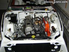
904Zster... Is that an OS Giken head or a custom built head?? (Green engine thumbnail) I am interested in people who make 4valve heads for our engines. Years ago was a guy here in Orlando FL who used to make 4 valve heads for the L-series. It would be interesting to see if there are others. Now that I've studied the picture I'm wondering if it is a L-24/26/28 motor or something else. Curious, Jim
-
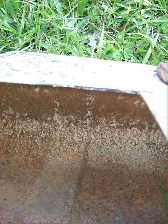
Ah yes... A good point. This is a very important part because of the severe explosion hazard. Should have put up a disclaimer like this... Gas tanks pose EXTREME explosion hazards which have been known to kill or at least break a few bones while sending someone across a shop. This is something which should not be taken lightly. Before beginning any work on a tank one should remove all traces of gas or anything combustible such as varnish which may produce vapors. Gasoline itself is highly flammable but one should remember it is the vapors which ignite and not the gas itself. Stay at least 100 away from open flames, water heaters, electric motors and anything else which could ignite the vapors. If something should ignite the vapors in a tank, the openings are unable to release the pressure resulting in a serious explosion. I've met a survivor of such an explosion. His description wasn't pretty and he confessed he was very lucky to have survived. Handling raw gasoline is equally as dangerous and requires extreme caution. Place drained gasoline in a sealed, approved container as soon as possible. End of disclaimer Here is what my research has found regarding creating conditions for safely work on a gas tank. (Welding, cutting, anything involving sparks or heat etc...) Since a mistake with a gas tank is a one time thing I'll list methods which have worked for some but should NOT be relied upon. Ususally the work being done on the tank was welding or sweating. The following methods though somewhat sound have FAILED at one time or another and should NOT be used... Filling tank with water Assuming tank that has set dry for a year is safe(Can't smell fumes) Purging tank with exhaust pipe. CO supposedly negates combustion. Purging tank with inert gas such as argon. (Similar to above) Washing tank with water Methods that work and what should be used... Take tank to radiator shop for boiling and any welding/sweating req. If you are doing it yourself... Drain all fuel and place in approved container. Use strong degreaser to thoroughly clean the tank. Clean tank until no residue is showing in waste water. A good follow up for the degreaser treatment is electrolysis as this will liberate a lot of crud that the degreaser might have missed. Electrolysis has dangers of it's own so I will make a page for the electrolysis and place in a later post. It's cool and it really works well. One shouldn't rely on it to remove all rust inside a tank despite using internal electrodes. Cut access hole in top of tank and sandblast. Stop occasionally and use a light and mirror to see what you've missed. When you have removed 90% of rust then drain sand and apply ospho to inside of tank. Let ospho set up for 24 hours and sandblast to remove all traces of it. Conduct any sweating or welding on the tank now that it is taken down to bare metal inside and out. Create and weld in patch for access hole. Apply metal prep such as Hirsh's tank etch to inside of tank. Follow product instructions. Apply tank sealer per instructions. See my original post for opinions/reasons for using RedKote tank sealer. Some people use muriatic acid to nix their tank rust but this is very destructive as it eats metal. If the chemical reaction isn't neutralized it could continue to eat things or rust out the tank. The way to be absolutely sure that the rust is gone is outlined above. Make sure that you focus on the seams and any areas which harbor rust when sandblasting. Ospho gets the rest but needs for there to be as little rust as possible for maximum effectiveness. Schew!!! That was a longgg post. Sorry. Beandip, you're absolutley right about the need for extreme caution/safety. Thanks Jim Attachments are post tank cleaning/electrolysis. Single "L" shaped electrode was used inside tank. Note how more rust was removed in areas closer to the electrode.

-
I'm finishing mine up. Did eloctolysis for a couple days using wahing soda and a little ospho. This stripped the paint and residual gas out of it. (Someone had coated the inside before) Cut an access hole in the top, sandblasted, and phosphoric acid treated it. I'll sandblast again and apply metal prep before applying RedKote. Redkote is a great gas tank liner and is used by my local radiator shop and others. It is something to look into at $31/qt. After having read all of the smear/neg advertising between Hirsh and POR I decided to stick with Redkote. The local radiator shop guy showed me the insides of a few tanks he was doing which had been coated by other processes. This greatly influenced me as well. It can be removed by soaking in MEK if one should need to remove and reapply. It also seal holes up to 1/16". Here is a video I made using a sample of RK. http://warbuddies.homestead.com/RedkoteTank_Liner.wmv I hear that Renu is good and that they bascially do the same thing. They use a different sealer though. Seems that they would provide a higher quality repair than most.
-
They winced because they wanted to sell you their service. Nothing wrong with caliper kits. What's wrong are how some people rebuild them. Sometimes people think they can get away with a scuffed or notched piston. This is one possible reason why caliper rebuild kits are becoming more difficult to obtain for many makes models. (Not just Nissan) I rebuilt mine a couple of times before getting new ones. I would assume that my calipers were rebuilt three to four times. All the rebuild is is an inspection , cleaning and replacement of rubber parts. Use chrome polish to clean up the pistons. The Ra (Surface finish) of a sliding seal surface is important) If one absolutely needed to polish a rough spot the 400 followed by 600 would do. This would give you a limited lifespan on the piston since it would now be prone to rust now that the plating is gone. Scrap the caliper if the piston is too far gone of course. Since our calipers don't have sliding bushings there is no need to measure anything else. Before you start trying to undo brake lines get a can of parts blaster or some other fastener unsticking stuff. Spray it on all brake line ends and let it set for an hour or two. Even a decent brake line wrench can strip things if the fasteners are rusted. Vice grips are the last resort but what a mess. Take your empty calipers to someone to be glass bead blast the bores for rust removal if you can. Some of the older caliper kits come with small O-rings for the caliper halves. Don't take the caliper halves apart unless you have these rings. It is better to not take the halves apart anyway. Simply following the instructions in your Haynes manual will get you through it. Hope this helps.
-
I've got a good one for you. Just helped another member install some floor pans. He mentioned that we might be able to get around to the battery tray area and after one look I decided that it would be better for another day. A fair amount firewall area on the inner fenderwell side had been duct taped and sprayed with undercoating. This would have been an easy fix if we had time to get the dash and A/C out. At least we got the new pans in. They were equally as bad in a few places. Ugh! The things some people pass on to the next guy. Your Z looks great though. As mentioned above, you still got a good deal.
-
The following are just a theorys since I can't find my manual right now. It also does not explain why only the front works but it is worth a try... One theory is that rear circuit may not be moving/retracting far enough. This would not allow it to "gulp" any new fluid from the reservoir. Do you see fluid movement when you pump?Make sure that the piston is not binding upon retraction and try screwing in the booster screw to a shallower depth. An improperly applied check valve in the MC comes to mind but your bench bleeding ruled this one out. Another theory is that a bleed point in your rear line is clogged. Removing the bleeder and checking for flow using air might help here. Bleeders can clog. Although extremely rare, flexible hoses sometimes rupture internally and close off. This could also give a no flow situation. Try pressure bleeding it. For starters, remove the brake line that goes to the MC rear circuit and open one of the rear bleed valves. Blow 10psi or so through and verify flow. Assemble MC to its lines make a cap which can be pressed over the reservoir and accept an air gun. Fill the MC half to 3/4, wear goggles, crack a rear bleed valve and apply light air pressure with your cap to force the fluid through. When applying air pressure do not exceed 15psi. Start with 10 or less and use a rag to limit splatter if there is to be any. Before removing pressure cap from reservoir allow a couple seconds to pass so that the air escapes. This way you won't get a big slosh of fluid all over. As I mentioned earlier these are just theorys of mine. Wish I could find a sectioned drawing of the MC's guts. That would help. Oh yeah, is all vaccum removed from the booster. I know you probably know better than to start an engine during bleeding but it's another thought.