


geezer
Free Member
-
Joined
-
Last visited
Everything posted by geezer
-
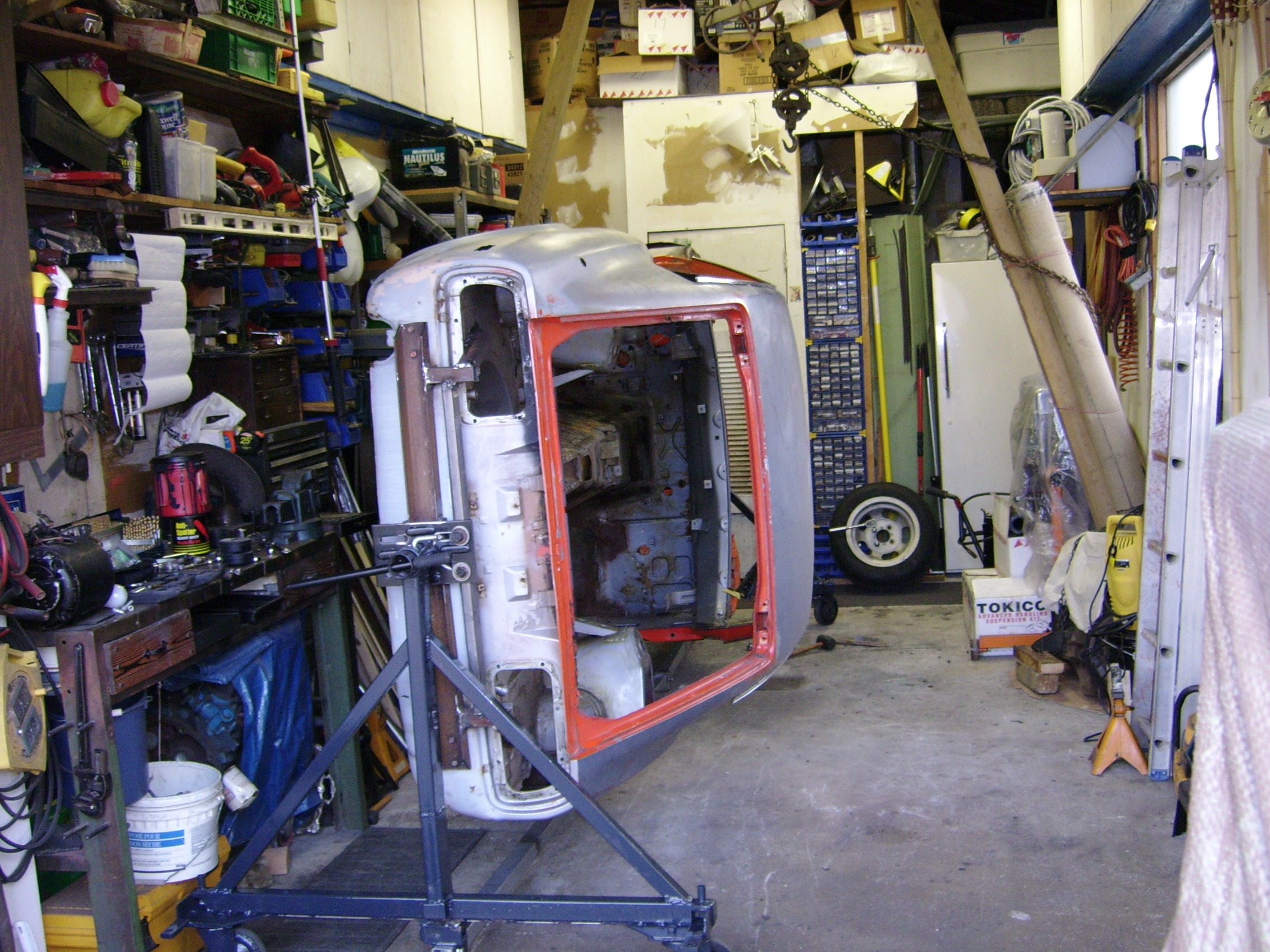
After removing the tail light assemblies, you could adapt a few more fastening points using existing holes. Not a very good pic but it illustrates a very stable set up that I have used.

-
Good to hear from you Jeff as well! Yeah, although Brian is a member here, he seldom posts. Give him a shout and he can fill you in on what he's been up to. I can say that he has solved his space problems and has even bigger plans for the future.
-
Hi guys, gals! I'm still kicking as well and drop in every so often to see what's shakin in the Z world. Thanks for thinking of me Jeff, I am doing great but did downsize my car and motorcycle interests. I sold my Z and my massive Z parts stash and my Z library to our buddy Brian (think he has 5 Zs now). I still have my touring Harley, Model A coupe hotrod and a new minivan and that's enough to keep me busy. I know that our shared love for Zs, means that another could come along at any time though. I have often wondered what became of many former active members and appreciated being notified of this thread. Keep on enjoying the ride! Ron.
-
Interesting question. I think the light is a visual aid as well as a failsafe in case the resistor suffers an open, ensuring the alternator field is energized. Likewise, if the light fails, the "mystery" resistor referred to would still energize the field winding. The diagram showing the resistor is probably not realistically illustrated but shown as an example of theory of operation. That leaves me thinking a fusible link is one means to provide the resistance value represented in the diagram. Just thinking out loud.
-
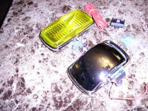
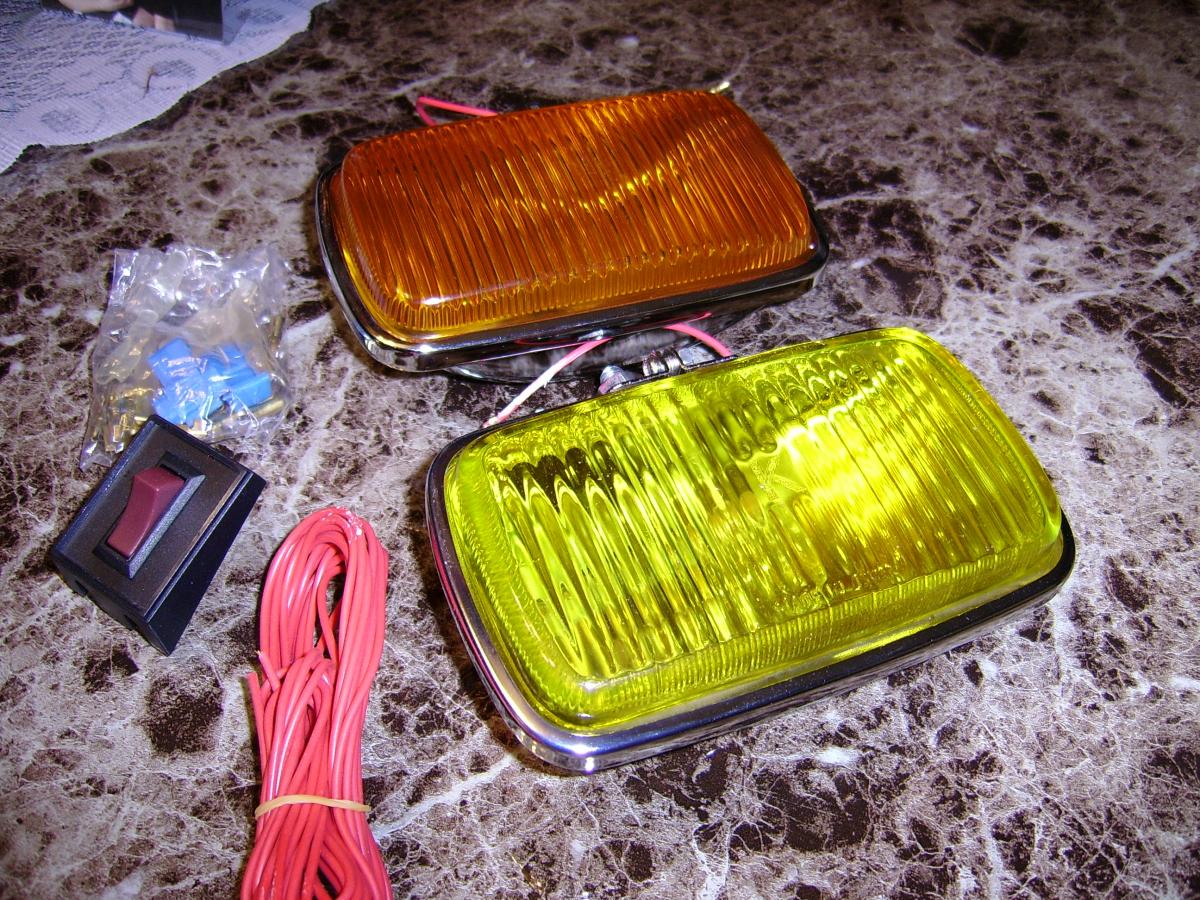
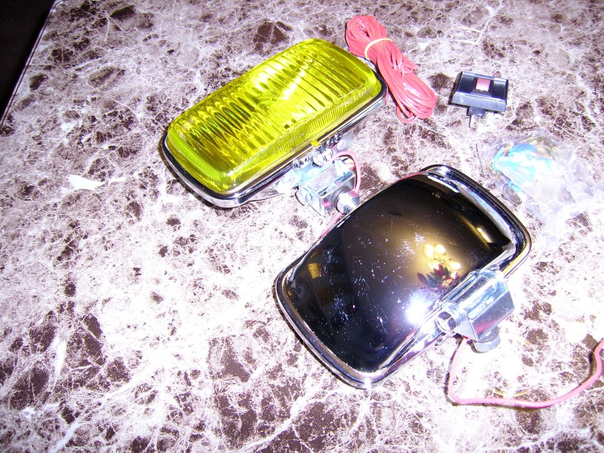
I have a few sets of aftermarket, cheap fog lights that I put aside until I decide if I'll ever use them or not. I found a pair of the yellow glass lenses that fit the housings well but they are still a bit too yellow, compared to the originals. I think they still sell these fog lights at Princess Auto for not much $. There is a set with what appears to be different mounts shown in the Sports Options Catalog on the rally drop/split bumper. That's a different look. I'll dig up a pic.

-
Funny stuff! My hats off to Alan and anyone else who attempts to educate the masses and I believe we are all the better for it. Nothing wrong with loving that velvet Elvis you have hanging on your wall but its still nice to get out to see the museum quality pieces.
-
This is the problem that I mentioned before. There were many revisions made during the course of the early years of the S30 build. I'm not sure if all the changes made it into print in our manuals and if they did, as in the 1971 Revisions Manual, undoubtedly there will be variations from the previous printing. In a perfect world the harness part numbers would be tied to the relevant drawings with "from - to" VIN guides. That's why there are so many diagrams out there. Some of them are labeled as "early" or "late" or "basic" and that isn't taking into consideration the different models/markets that have other features, such as that "passing relay". Its long been a problem for some of the guys with the very early build 240Zs to find an appropriate diagram for their needs. I haven't proof read your entire diagram and I don't know if anyone could improve upon it or find any mistakes. Most would turn out to be just a case of the diagram not jiving with the particular harness because of changes made. Most of us probably have several versions, I know I do. I don't have my Z or any harnesses handy, but the rule of thumb for bullet connectors is, when unplugged the one that is still providing current should be "female" to prevent accidental shorting. Maybe, someone has a car handy, to check. I think the -20016 service manual has an explanation for the numbered connectors on that blower wiring loom. I'll see if I can find it. Edit: The only info for that particular drawing of the blower wiring loom is on page 27 of the '71 supplement manual. It wasn't in the earlier manual. 54 - Air conditioner power source - Blue 55 - Blower motor power source - Red 56 - Blower motor ground lead - Black 57 - Intermediate wire harness blower switch/motor
-
Very nicely done! It will be suitable for framing and hanging in the man-cave where it will do the most good and look great!
-
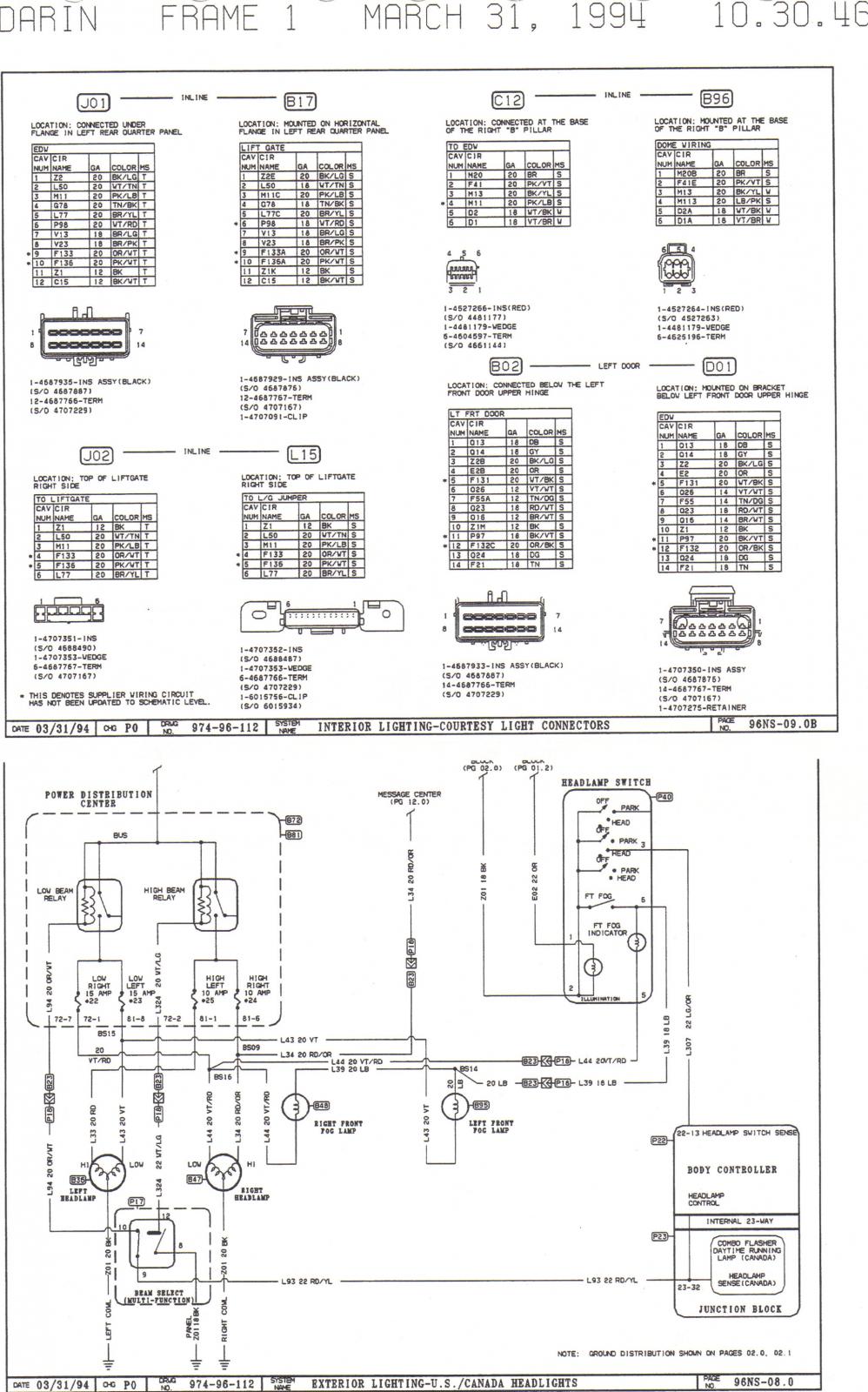
A few thoughts come to mind if an improved drawing was to be made. The accompanying pages Blue posted (post#33), as an example, would be great for reference, especially if the suggestion he already made, assigning ID codes to the connectors was included. They could be coded with a "F" or "M" as a prefix to the number assigned, on the wiring diagram to designate male or female as well. The wiring drawing itself could include other information such as wire gages, assigned circuit ID numbers, along with the proposed connector ID numbers. A color enhanced drawing does make color labelling on the wires somewhat redundant. The additional info sure would help to make it easier to troubleshoot problems with these cars and make the diagnoses something easily learned even if wiring isn't in your comfort zone. The examples, I posted (post#31) were just random pages taken from circuits that it was my job to proof read in 1994, two years lead time for our 1996 NS launch. They just show how much more info was included to aid in reference pages (and that was more than 20 years ago). Everything from connector info, pin out info, to circuit theory and explanations.
Wow, beautiful work Captain! Temperature can play havoc with polyurethane finishes on wood. Years ago I learned the hard way that kitchen cabinets being sprayed in the garage as the temperature was on the rise, caused the air within the wood to expand and cause minute bubbles on the surface before completely drying. I since have learned to avoid this by spraying when the ambient temperature is on the decrease. The vacuum heat curing process is interesting and wouldn't surprise me in the least if it is found that the originals were done similarly. They did have a process that stood the test of time with the steering wheels as well making them very durable.
Easy to get snow blind after looking at these circuits too long. Hey, you are doing great and we will all benefit from your efforts. Keep up the good work.
The heated glass should get its ground from a door switch wire splice.
Other markets/models had a button on the end of the turn signal stalk. When depressed the headlamps would momentarily flash, the same as our "optical horns" do today. The passing relay has 4 wires connected to it. The R/W (red with white stripe) is spliced into the headlight dimmer wire. The Black is a ground wire. The Red is spliced into the headlight 12V circuit via a fuse to the fusebox busbar. The B/Y (black with yellow stripe) makes a straight run to the passing switch, which is the white button on the end of the turn signal stalk, if so equipped.
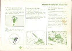
Pardon the crappy, scribbled on example. That's cool, I've never seen the re-print manual from '97. Here is a link discussing a few of the versions covering the '69 builds as well as the '70. http://www.classiczcars.com/topic/24817-1970-240z-owners-manuals/?hl=%2Bowners+%2Bmanual+%2B1970 I don't have the proper one for my 10/70 but looked at one dated 15th November, 1970 and page 15 seems correct with the description and illustration of the defroster switch on the far right of the page. The earlier cars did not have a rear window defroster, in North America anyhow.
 I'm sure I remember this car. If memory serves me correctly, some of us had a few light hearted sparring matches with the former owner. He was banned from this site eventually for his lack of political, ethnical, etc. correctness. The oil canning problem he had on the left side floor pan and the bumper over rider are two of the concerns he had at the time as well as his problems coming up with the correct color for the tail light finishers. I cannot remember his "user" or real name. Jar anyone's memory? It's a nice restored car but in my opinion, certainly will not command the price he thinks.
Hello Jerry...this is as good a place as any for a group meeting. Most of the afflicted frequent these pages. I too have a problem (but only in the eyes of others). I only buy Z parts to better the ones I already have, then occasionally sell off the extras to make space for more inventory. Its been my experience that in most cases a profit can easily be made within a few years time, just by selling at the going prices. You already know this but just need to educate your wife in Zeeconomics. Good luck with that! Not much help huh!
I had to open that seam up to clean/blast and reweld, re-seal as well. It was/is common practice to apply seam sealer between all metal mating surfaces before spot welding. It expanded and cured after going through the paint oven. This served a dual purpose. It acted as a sound insulator, preventing harmonic vibrations and to seal and protect from the elements. Seam sealers have been improved greatly over the years with both better adhesive properties and much less moisture absorbtion. Rust never rests and breeds where we don't see it until it has spread far enough to cause problems or become an eyesore. Taking care of these problem areas will ensure these cars will live on a long time. I had the advantage, (yeah right) of working on a totally disassembled, bare shell, which makes it much easier to access and remove the rust especially on these North Eastern "sort of survived" Zs.
Thanks for the link and attachment Blue. It is an interesting topic that at this point, I can only partially comprehend but enjoy reading and hearing the results of the testing just the same.
Interesting chart. At first glance that chart would seem to prove the old adage, "less is more". Do you have the link to the article with any descriptions of statistical models? It must be a science of infinite variables. The correlation coefficient such as a slight lip radius deviation alone would change the results drasticly. I've thought about this some, ever since I bought a Z from the Boston area from a guy who said his grandfather had done years of research and testing and had come up with the theory that the short stubby, home spun versions he had made, although crude, were very efficient. They were mounted on a triple set of Weber DCOE45s and fit nicely under the K&N filter housings. I still have that set. He had made me promise not to change a thing until I at least tried his set-up. I haven't yet but hope to one day and thought I might even try to improve on the design and make new ones.
I welded new metal in for my cowl chimney repair and flowed some two part epoxy similar to the type shown in this link. It bonded permanently to the epoxy primer, creating a perfect, tougher than nails seal and I wouldn't want to be the guy trying to remove it. I wouldn't hesitate using these products or something similar on an area such as these cowl chimney leaks. Master Bond Epoxy Systems for Metal Bonding | MasterBond.com
Have you made a visual comparison between the old and new caps and rotors? If so and nothing is readily apparent, try putting the old rotor back in and if that does nothing try swapping the old cap back on as a process of elimination. If that doesn't get results you will have to use the standard troubleshooting flow chart to track down the problem. Good luck!
LinParkFL, if you read that thread I linked to, I mentioned using one of the adhesive panel bonding products. They have come a long way in recent years and I'm convinced that a cowl repair could be done quite effectively after cutting an access opening. We just need someone daring enough to try it and report back with pics. It would be especially helpful for someone trying to avoid disassembly and heat from welding. It is necessary to cut an access opening somewhere on a '78.
On my 4X4 trucks that were run mercilessly in extreme weather and regularly submerged in the muck, I would always run a small amount of axle grease around brake fittings but only after they had been tightened. Never had a problem with brake contamination or loosening fittings. I imagine that would be a good solution/precaution for any vehicle. I like the vise grip method of loosening as well. It is worthwhile taking the extra time to ensure slippage does not occur. Another thing I do occasionally when using flare wrenches is to dip them in a tin of valve lapping compound, preferably coarse. That gives a lot more grip and less chance of slippage.
I'm sure I remember this car. If memory serves me correctly, some of us had a few light hearted sparring matches with the former owner. He was banned from this site eventually for his lack of political, ethnical, etc. correctness. The oil canning problem he had on the left side floor pan and the bumper over rider are two of the concerns he had at the time as well as his problems coming up with the correct color for the tail light finishers. I cannot remember his "user" or real name. Jar anyone's memory? It's a nice restored car but in my opinion, certainly will not command the price he thinks.
Hello Jerry...this is as good a place as any for a group meeting. Most of the afflicted frequent these pages. I too have a problem (but only in the eyes of others). I only buy Z parts to better the ones I already have, then occasionally sell off the extras to make space for more inventory. Its been my experience that in most cases a profit can easily be made within a few years time, just by selling at the going prices. You already know this but just need to educate your wife in Zeeconomics. Good luck with that! Not much help huh!
I had to open that seam up to clean/blast and reweld, re-seal as well. It was/is common practice to apply seam sealer between all metal mating surfaces before spot welding. It expanded and cured after going through the paint oven. This served a dual purpose. It acted as a sound insulator, preventing harmonic vibrations and to seal and protect from the elements. Seam sealers have been improved greatly over the years with both better adhesive properties and much less moisture absorbtion. Rust never rests and breeds where we don't see it until it has spread far enough to cause problems or become an eyesore. Taking care of these problem areas will ensure these cars will live on a long time. I had the advantage, (yeah right) of working on a totally disassembled, bare shell, which makes it much easier to access and remove the rust especially on these North Eastern "sort of survived" Zs.
Thanks for the link and attachment Blue. It is an interesting topic that at this point, I can only partially comprehend but enjoy reading and hearing the results of the testing just the same.
Interesting chart. At first glance that chart would seem to prove the old adage, "less is more". Do you have the link to the article with any descriptions of statistical models? It must be a science of infinite variables. The correlation coefficient such as a slight lip radius deviation alone would change the results drasticly. I've thought about this some, ever since I bought a Z from the Boston area from a guy who said his grandfather had done years of research and testing and had come up with the theory that the short stubby, home spun versions he had made, although crude, were very efficient. They were mounted on a triple set of Weber DCOE45s and fit nicely under the K&N filter housings. I still have that set. He had made me promise not to change a thing until I at least tried his set-up. I haven't yet but hope to one day and thought I might even try to improve on the design and make new ones.
I welded new metal in for my cowl chimney repair and flowed some two part epoxy similar to the type shown in this link. It bonded permanently to the epoxy primer, creating a perfect, tougher than nails seal and I wouldn't want to be the guy trying to remove it. I wouldn't hesitate using these products or something similar on an area such as these cowl chimney leaks. Master Bond Epoxy Systems for Metal Bonding | MasterBond.com
Have you made a visual comparison between the old and new caps and rotors? If so and nothing is readily apparent, try putting the old rotor back in and if that does nothing try swapping the old cap back on as a process of elimination. If that doesn't get results you will have to use the standard troubleshooting flow chart to track down the problem. Good luck!
LinParkFL, if you read that thread I linked to, I mentioned using one of the adhesive panel bonding products. They have come a long way in recent years and I'm convinced that a cowl repair could be done quite effectively after cutting an access opening. We just need someone daring enough to try it and report back with pics. It would be especially helpful for someone trying to avoid disassembly and heat from welding. It is necessary to cut an access opening somewhere on a '78.
On my 4X4 trucks that were run mercilessly in extreme weather and regularly submerged in the muck, I would always run a small amount of axle grease around brake fittings but only after they had been tightened. Never had a problem with brake contamination or loosening fittings. I imagine that would be a good solution/precaution for any vehicle. I like the vise grip method of loosening as well. It is worthwhile taking the extra time to ensure slippage does not occur. Another thing I do occasionally when using flare wrenches is to dip them in a tin of valve lapping compound, preferably coarse. That gives a lot more grip and less chance of slippage.


Important Information
By using this site, you agree to our Privacy Policy and Guidelines. We have placed cookies on your device to help make this website better. You can adjust your cookie settings, otherwise we'll assume you're okay to continue.