geezer
Free Member
-
Joined
-
Last visited
Everything posted by geezer
-
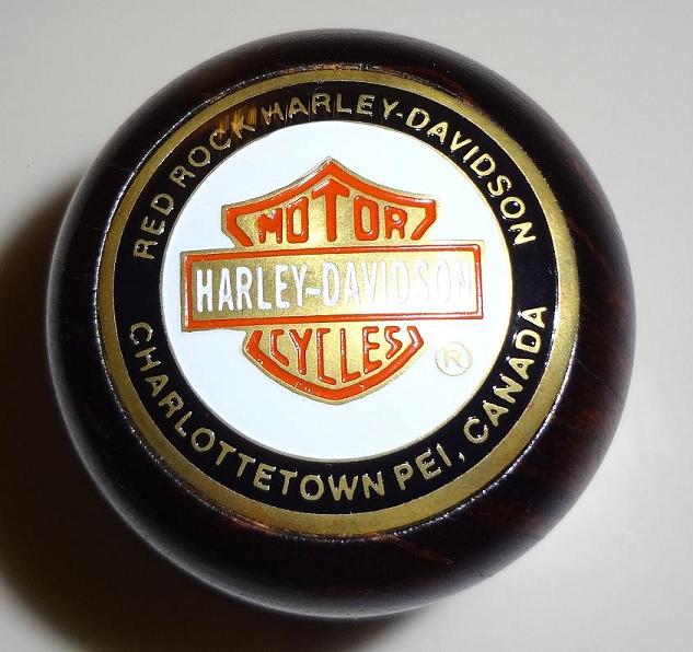
It came with the taper attachment and a ton of tooling. I almost bought the milling attachment to go with it but have been advised to hold out for a dedicated upright machine. I've been collecting these domed large metal "dots" at various HD dealers. They are a couple of bucks apiece. Just for the heck of it, tried one in an early Z knob. A perfect, very tight friction fit without even removing the adhesive backing. The knob has the same feel as one with the stock plastic shift map. Figured some may like that idea...or not.
-
bhermes - Do you have a knob to make a pattern? I have some extra knobs. If you would like to borrow one to make a pattern from, PM me. Well Captain, I bit the bullet and bought an old metal lathe from a local school maintenance department. Its a Southbend 10K, not as old as me, but close.:laugh: This should save me several trips a year to a machinist. I bought it mainly to support my other hobbies but will attempt dissecting the aluminum knob in order to make a shift button and base.
-
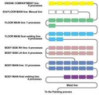
This makes perfect sense and fits in with what I have been able to find from Nissan's manufacturing process at that time. In the Nissan generic flow chart below you can see the manual line depicted. This is where "hand built" operations would have been carried out, at their own pace, independent of the production run. Not shown in this simple chart would be a rather large staging area supporting the special build. Purpose built components could be injected as needed, at any point in the manufacturing process. There is a clue on this flow chart that could identify its location. The manual line is labeled with a physical floor location which is typically found in any metal shop, normally found on the pillars. Sorry for the side track, and I did post this once before but I thought some may find it interesting.
-
Very interesting to say the least and you can be assured that this beautiful example has not gone unnoticed. I hope to see many more pictures of the process and refreshed car, knowing that I likely may never see one in person. It is a real treat and I would like to thank Takeuchi san for sharing this treasure with us.
-
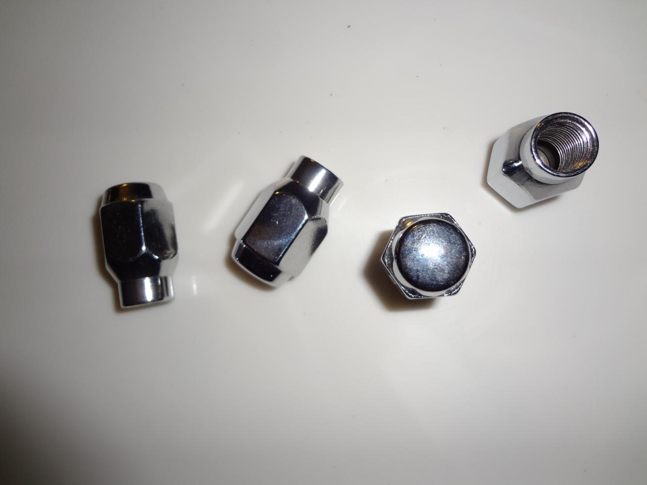
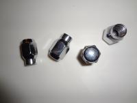
Do the existing lug nuts fit properly? Sometimes you will have to match up the wheels with the lug nuts making sure you are engaging enough thread on the studs as well. The tapered shank type are a little harder to match up, especially when buying on line. It took me a while but I finally found a set of lug nuts that match up perfectly with my Watanabes without paying the price they wanted.
-
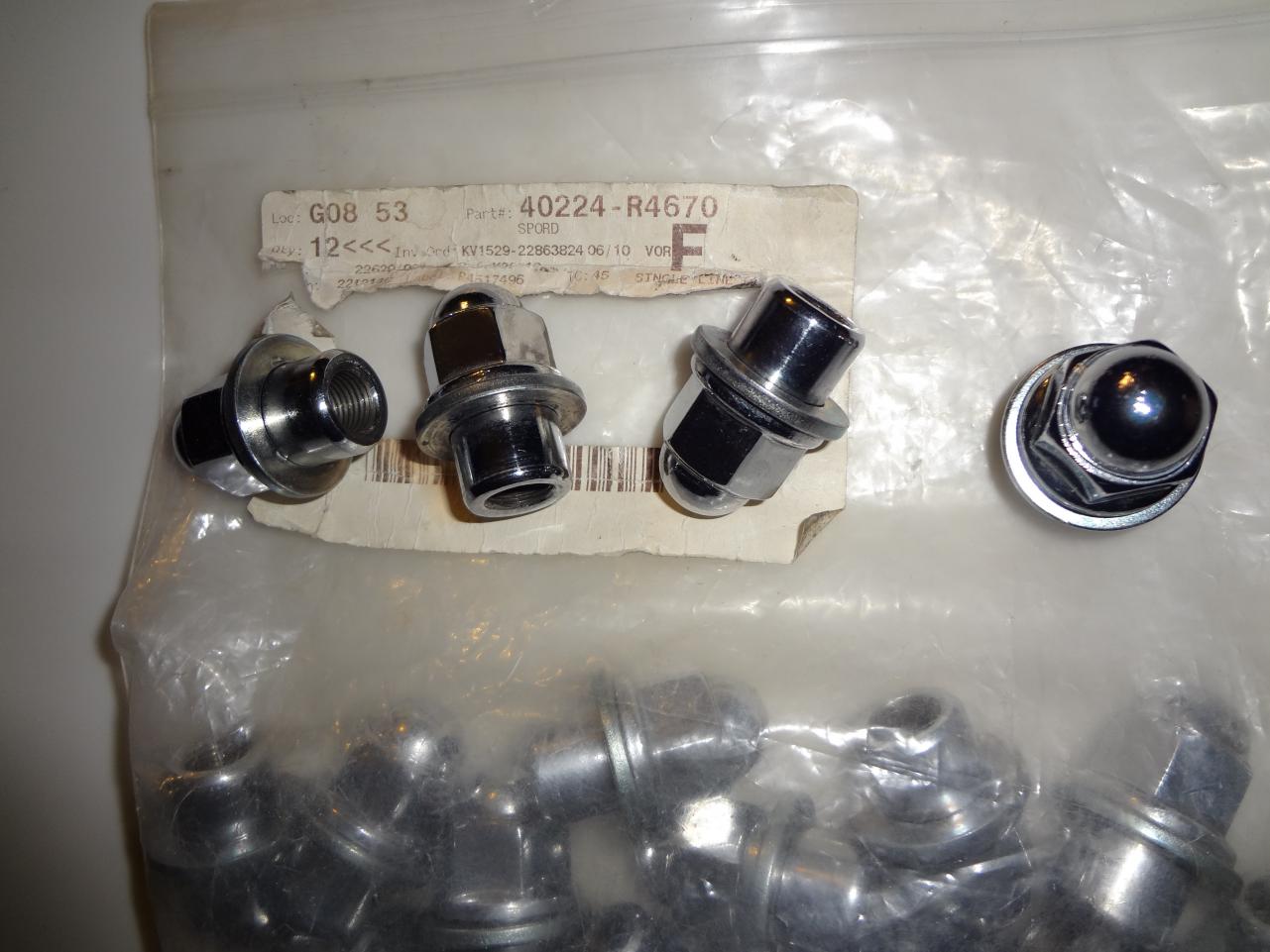
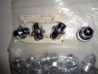
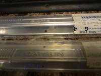
These are stock lug nuts with the part number for aluminum wheels.
-
Get one of those volume knobs that goes to 11.:laugh:
-
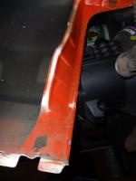
You don't want to do a mig weld repair and these are in areas that are not seen and can be easily checked occasionally, correct? If so, if it were me, for just making a few screw holes disapear, you could prep the area, use a touch up gun or brush to apply some epoxy primer and then flow an apropriate amount of JB Weld or similar two part epoxy product over it and allow it to cure. Take care of both sides if accessable to prevent any water traps, then flare out the repair area with a suitable paint/sealer.
-
I have some NOS kick plates that are still in the original plastic. They really were not finished to perfection when new. They are a a semi gloss finish that appears to have been anodized before being stamped. The press marks are quite visable. Don't know if they will show up through the plastic but I will attach a pic. I don't think these would be easy to duplicate today. Easiest way would be to stamp new ones but the dies would be cost prohibitive. Another way to achieve the look would be by milling light gauge aluminum angle stock that can be formed to the proper angle which is less than a 90. Anyone reproducing the vinyl covered inner steel trim plates shown in the pic? They have a bit of a tricky profile to duplicate as well.
-
, Good one! Since this thread has arisen, I will share with everyone what I use to remove 3M or other foam adhesive strips. I find that PBBlaster will totaly disolve this material when liberally applied and allowed to do its magic. No scraping or difficult cleanup, just wipe off with a rag or paper towel. It doesn't seem to effect the paint finish but I do rinse with warm soapy water just as a precaution.
-
I agree with this but at what price point could this be accomplished and still be profitable? Sure, even used ones are selling for astronomical prices at present because of the "rarity" but after there are a thousand cars equipt with reproduction pieces they wont be so unique and demand will decrease along with the amount someone is willing to pay. It really is a limited market that is IMHO risky, considering the development costs involved. Stainless bezels have been plagued with splitting problems as well from I suspect overtightening. Thermalforming appropriate lenses seems easy enough but would have to be farmed out to someone who has the needed equipment. The limited Z market would most likely not justify the expense of molds and thermalforming as a singular venture. There is good reason nobody has continued to successfully reproduce these parts but having said that, I still hope someone actually does it.
-
The stainless hardware kit from MMS does not include much of anything for fastening front and rear suspension parts. I think the reason for this is in part to protect themselves from liability issues that could arise, as well as the increased cost that would be associated with supplying these pieces. Other than that, it is a very good kit for someone not too concerned with keeping completely original appearances for the entire rest of the car. Very convenient. Bring a list with the correct part numbers of the hardware needed to your local dealer first, if you can't get by with your cleaned up stuff. Then you will will have to check with aftermarket suppliers, some of whom sell in kit form. I take an interest in this subject because myself and a local Z buddy/guru have actually undertaken the task to compile a complete list of every fastener on a series 1 Z. We methodically went through the parts catalogs and the microfiche and identified the fasteners, then located the actual physical pieces and measured them and have cataloged the results. But unfortunately thats as far as the project has progressed so far. We don't have anything to sell.
-
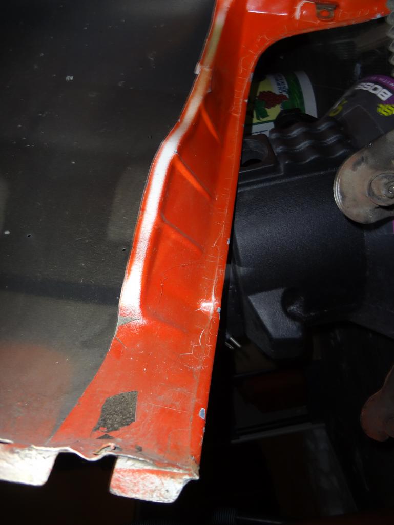
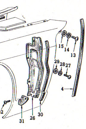
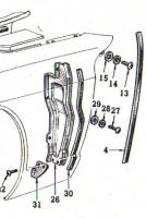
I have a few fenders hanging in the shed, not for sale but I took a pic of what you are describing. That part was/is not sold separately but is part of the fender assembly. The rubber is listed in the parts catalog as: FILLER-baffle front fender,part number 63810-E4100. At first I thought you were talking about the Mud Guard in the illustration.
-
I have used heat with the 50/50 acetone/ATF mixture after leaving it work its magic for a few minutes. The acetone evaporates in a matter of minutes but not before doing the intended job of getting the ATF where it is needed. It actually wicks uphill quite well on rusted metal and does a great job of penetrating tight rusted fittings as well. In years past, we would pick up PBBlaster while visiting in the US, not being available here and I had never heard of Kroil but after reading about acetone/ATF in an online article, thats all I use now for getting stubborn things to come apart. A great old time tip. Price is right too.
-
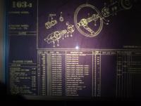
Good eye Chris. Also, on the first line they have omitted 6/70 to 12/70 builds or more likely, 5/70 was a misprint.
-
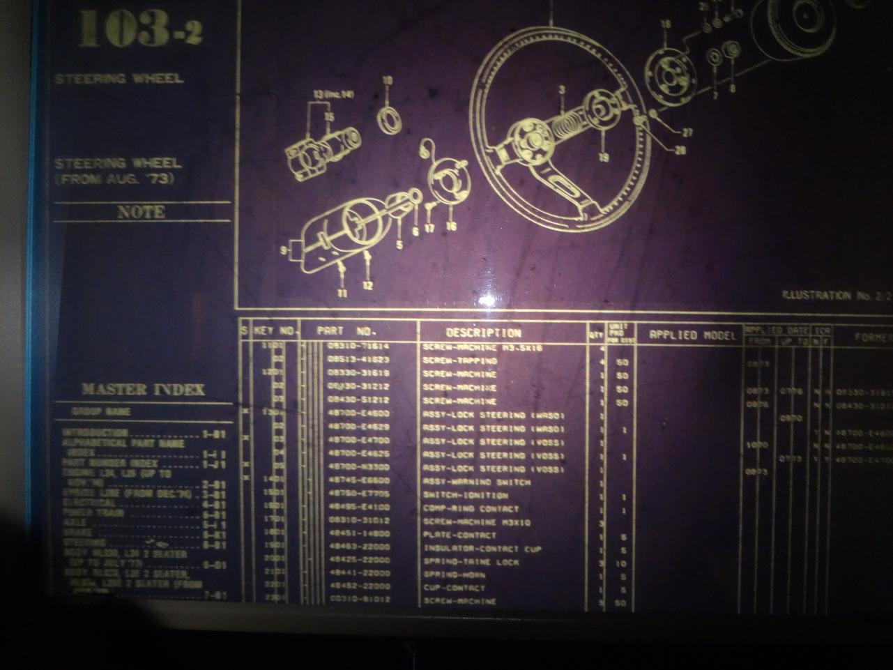
The clamshell screws shown in the US/Canada Parts Catalog 1970-1973 as well as the microfiche show a machine screw used up to July '73 (M3.5 X 16). Aug '73 is when the revision is found, changing to a self tapping screw. Not that critical, so just use what you have that is a good fit and does the job or if you want the part number, it can be found below in the 'fiche if you want to check for availability. EDIT: Kind of a crappy pic, the part number is 08513-41623
-
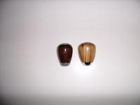
Wouldn't want to disect that one, it was costly and is now finished. I don't know if the new OEM knobs have the same center hole or what the differences are between inserts, not having had it apart. I only turned the wood down and refinished it with Minwax "Ipswich Pine" stain and a few coats of a polyurethane clear spray.
-
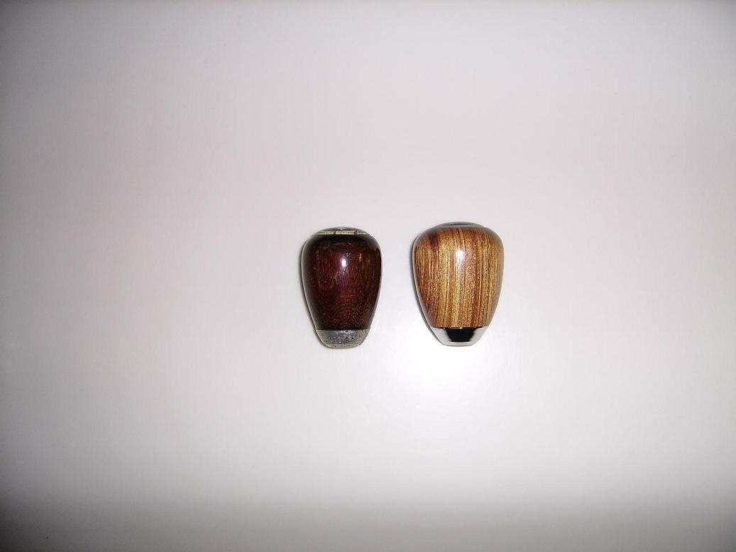
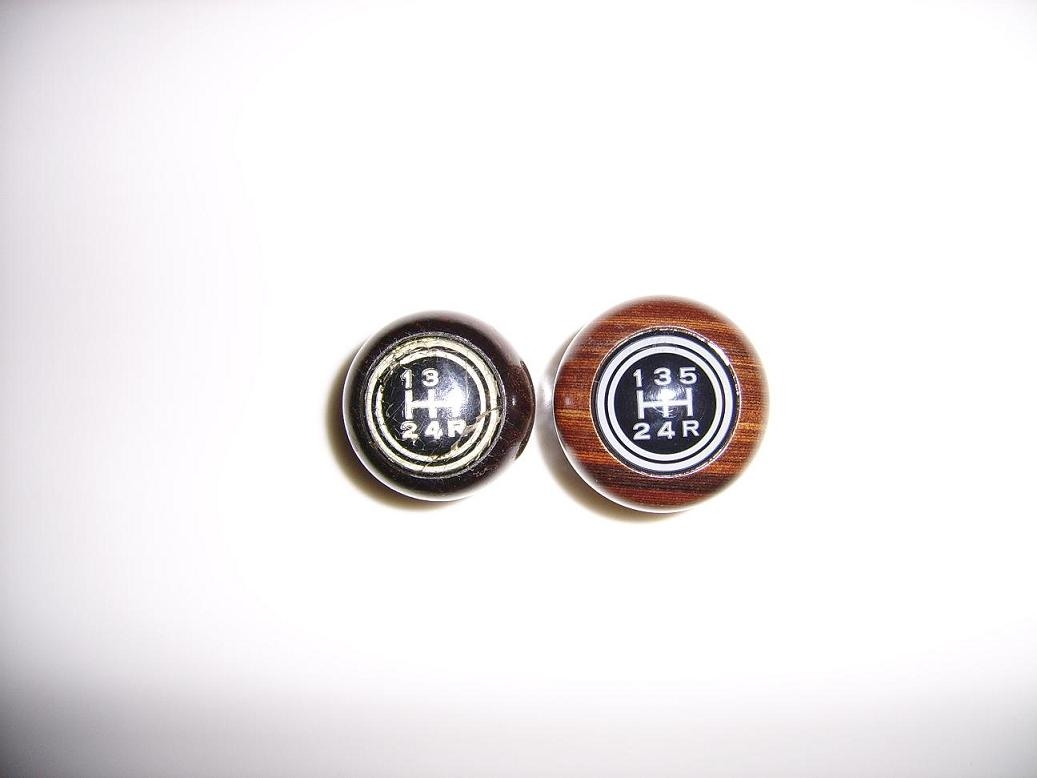
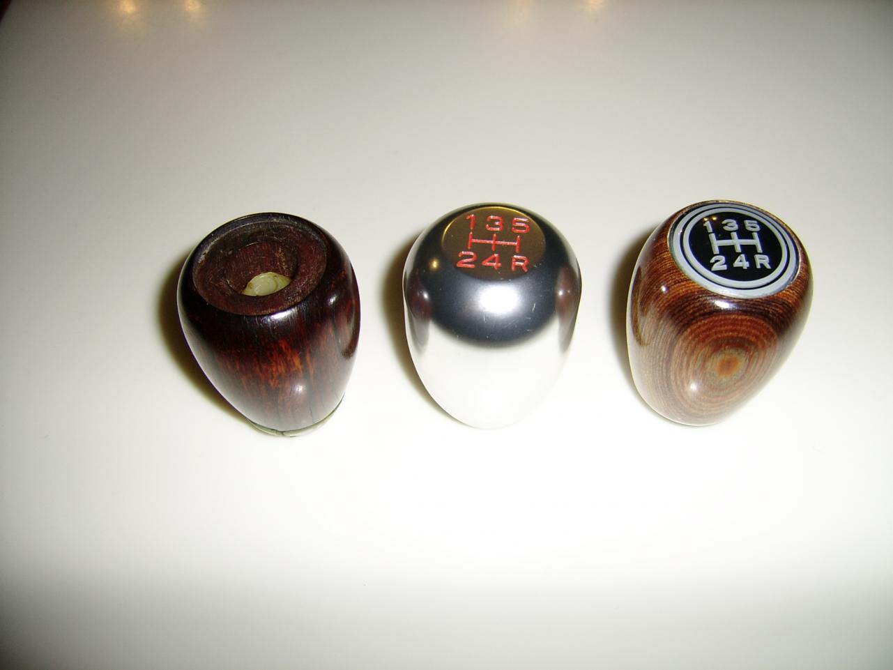
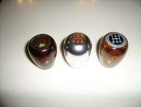
Mike, That is a new OEM 5 speed knob that I turned down a few years ago. It was much larger in diameter originally. In the 3rd pic after turning it down, you can see it is shaped differently than an original stock knob and is a bit taller as well but still quite an improvement over a new OEM IMHO. The first pic as well as the overhead pic showing the map is before I turned it down. The milky white coloring of the map still throws me off too. Why they changed that as well as the dimensions is a mystery to me.

-
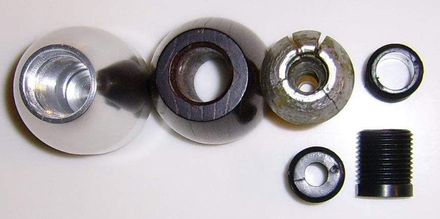
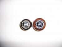
Capt, thanks for the interest in this concept. No material needs to be removed from the top. Both circles can be cut starting at the edge of the flat and emulate the original in size, as well as fit perfectly into the recess in the top of the knob. Once powder coated and the white circles and map are applied, I'm hoping it looks quite similar, just made from different material and be more durable as well. This pic may help you visualize the delemma with making an insert from the remains of the knob. The inner thread is much larger because of the plastic adapters used to make the knobs a universal fit. Only so much material could be removed before reaching a safe diameter that won't weaken the thread. It can be done but the hole in the stock knob would need to be a greater diameter, thus perhaps weakening the old wood. It is plain to see how the original knobs were made from two booked pieces joined together as I mentioned before.

-
Thats cool Capt! Nice coloring, looks great! I have the $9.00 aluminum knob that I bought on Ebay in order to dissect. The font is slightly larger and the inner circle will have to be cut right into the ridge around the map to lessen its presence. Really can't round that ridge off much without cutting into the shift map. Once both circles are cut and I have it powder coated black with the white lettering, I'll post a pic of it mounted in my original knob. I've been studying it to see if the bottom insert can be cut from this knob as well. It can, but I would have to enlarge the inside hole in my original knob to recieve it. I wanted to avoid that so, I may just make a new insert that can fit the existing hole. Edit: Woops, this should have been posted in the Making a Wooden Shift Knob thread. Can anyone move it? Thanks.
-
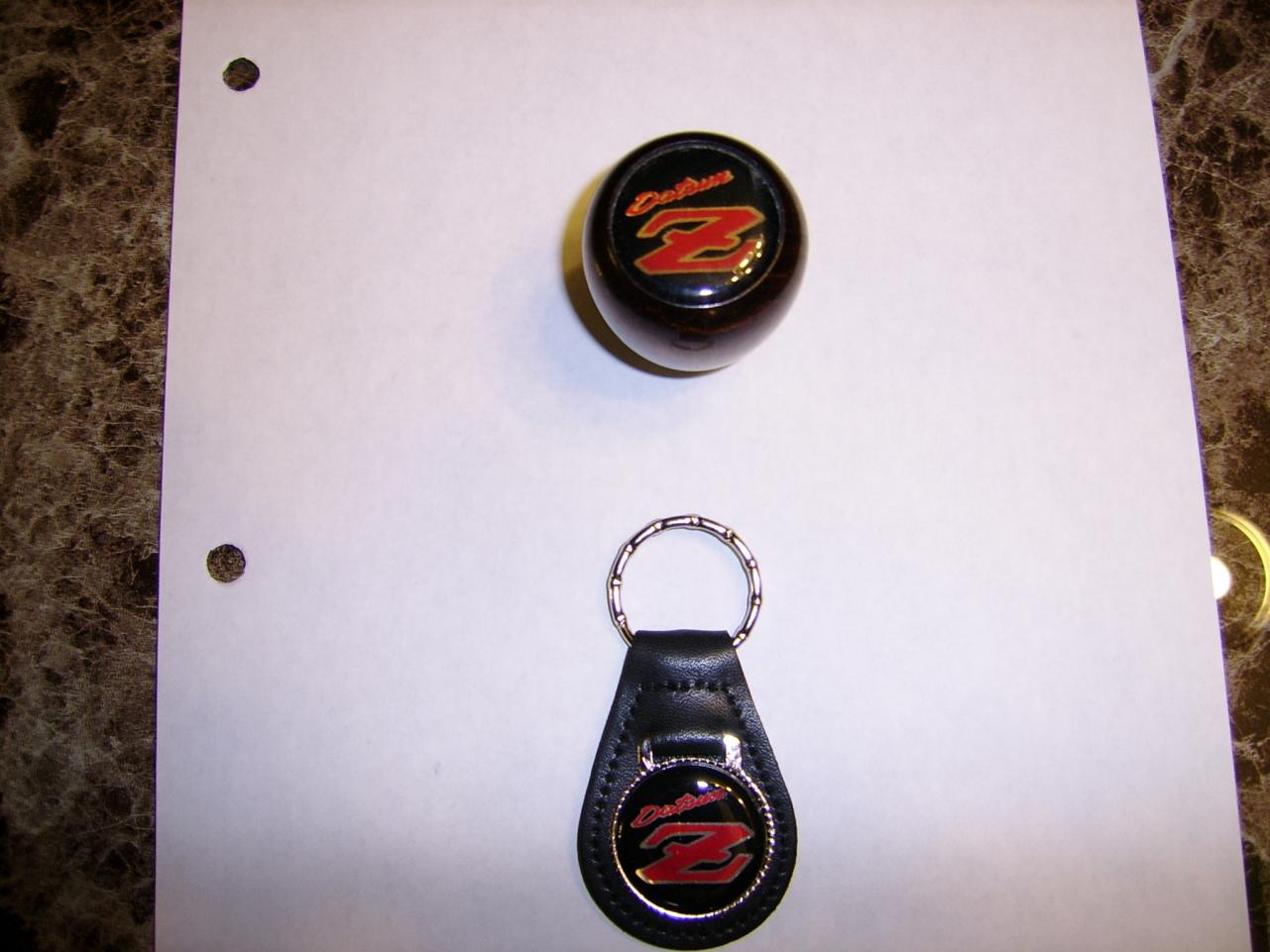
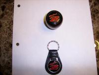
Some of the new keytags that you get for $1.99 on Ebay aren't too bad and the vinyl buttons can be carefully removed with a little heat from a heatgun applied to the backside. You can immediately stick them on a knob and they fit well.
-
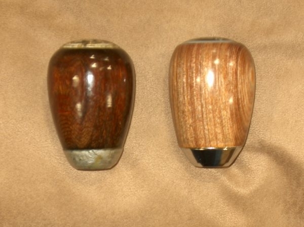
Its your thread, reply as much as you want. That side by side pic really shows that you aced it. One thing I know about maple is, it is really difficult for stain to penetrate into it being such a hard wood. Could take several applications to achieve the color you want. I wouldn't hesitate using a darker stain or at least experiment with different ones on your bowling pin first.
-
In the description it says...Material: aluminium alloy. I'll let you know for sure when it gets here. I don't have a lathe, so I think I'll farm this out to a machinist friend. Guy - There are a few threads explaining why one would go to these extremes to create a knob to replace their stock one. I have several knobs including the one sold as OEM today. They are much larger in diameter and just don't fit the hand as well as an original. Price an OEM with a 5 speed map today. You won't get one at the dealer for $48.00 and the dimensions as well as the shift map are different. Besides that, its fun!
-
Yep thats it Mike. I have a link to the Ebay auction in my last post if anyone else wants to attempt making a new map button from one of these. I might even be able to make an insert from it as well. If I screw it up its only a $8.99 loss. Cutting the two circles will be the difficult part. Without having it in hand yet to measure it is a bit of a guessing game. If the shift map is close enough to my original in font size and the two circles can be cut into it after rounding out the top some, it just might work out OK.
-
WOW!! Great job! I was looking for the easiest, most economical way to replace my shift map. I was never very impressed with the longevity of the acrylic stock map buttons that crack so easily, or the milky look of the new ones available so I looked at everything available on Ebay. I found this cheap aluminum knob that has a reasonable facsimilie of the map cut into it. I am going to attempt to reshape it, cut the two circles around the perimeter and then cut the end off creating a new button. Then I will get it powder coated black and paint the inset map white. http://www.ebay.ca/itm/180870642618?ssPageName=STRK:MEWNX:IT&_trksid=p3984.m1439.l2649