Everything posted by Nissanman
-
Trying to get her started
Usually, the variation in sides is a result of whether or not the engine was fitted with AC. Of course in the repair shop, a non-AC crank pulley may have been fitted to an engine with AC front cover timing marks, or vice versa. Nothing mechanically wrong with that BUT, it puts the timing reference marks WAY out of whack:rolleyes:
-
Trying to get her started
There is a similar discussion on this problem which you might find helpful, http://classiczcars.com/forums/showthread.php?t=27188 As previously mentioned, you may need to work backwards to determine where the TDC pointer and crank pulley notch need to be. It is the KEYWAY on the crank that will tell you piston TDC.
-
Tire size question
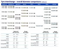
Here is a reference chart for Tyre Sizes both diameter and width, on specified rims. It won't tell you if tyre "A" will fit your car when fitted to rim "B", but is a handy table nevertheless. It is an old brochure but I believe the information is still valid:)
-
Fuel lines
-
When did brake rotor hat height change?
The rotor for all 240Z cars, 1970-1973 has a "hat" dimension of 52mm or 2". The manufacture includes the rotor thickness in their "hat" spec. If you add the rotor thickness to your measurement of 1.5" that gives the right spec for a 240Z rotor. However, for 260Z cars, 1973-1978, the "hat" dimension is 43.5mm or 1.7". 1.25" plus rotor thickness gives 1.7". So, what you have are 260Z rotors. The critical bit is locating the disc rotor in the centre of the calliper you wish to use. Unless the hub+rotor combination puts the rotor smack in the middle of the calliper slot, it ain't going to work:angry: If your mix and match achieves the correct rotor placement, it will probably be OK:nervous:
-
Fusible Link for a 240 Z
Depending on how original you want your car to be...... It might be more practical to use MAXI BLADE fuses in place of the factory fuseable link. They are a lot easier to check and replace and come in a variety of ratings: - Dimensions in mm. http://www.narva.com.au/Fuses_5.html Narva, for example, also sell FUSE LINK WIRE in an assortment of ratings as well as modern FUSEABLE LINK mountings: - http://www.narva.com.au/Fuses_6.html
-
Yet another rust thread
That is a fairly typical result when that stupid engine bay drain and box drain get clogged up:eek: The panel is reasonably important so the rustout will need to be cutout and new metal welded in. Your surgery lines are good. Try not to disturb those captive nuts if possible. I would slice the spot welded channel off the flat panel leaving the captive nuts in place. Repair the flat panel from the wheel well side with patches cut to size. Then fold up a new channel, may need to be done in 2 or 3 sections, and weld it to the flat panel and to each section. The flange can be welded either with new spot welds or plug welds if using oxy/acet. It will all be hidden under the guard skin so don't be too concerned with final appearances. Here is you chance to make that wuzzy little drain hole something more useful:) Don't forget to give the inside of the channel a good dose of Fish Oil to protect it from Deje Vu.
-
Fuel gage/sender problem - how to test?
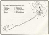
Refer to the thumbnail attached: The gauge terminal of the tank transmitter can be temporarily connected to earth and that should force the gauge to read maximum scale, if everything else is working OK. As mentioned, there are a fuseable link and a fuse to be checked in the Fuel Gauge circuit. There is also a Voltage Regulator, shown at the LHS of the gauge, which controls the voltage applied to the gauge. These have been known to misbehave and cause erratic readings usually on the Fuel and Temperature gauges. Cleaning the contacts on the VR and all points in the diagram may remedy the problem.
-
rack and pinion-name that part?
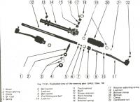
...or P/N 13 in this diagram. As mentioned, replace it with a conventional grease nipple and the world will be a better place:)
-
Fuse box upgrade
Motorsport Auto have a plug'n'play fuse box replacement. Sounds and looks good for minimum effort:) Web site here: - http://www.thezstore.com/page/TZS/CTGY/SEIC04D Not real cheap, depends on how bad your original one is I guess.
-
Does anyone know anything about these rims?
DELTA alloy wheels were/are an Australian manufacturer. Google tells me this: - I assume they are still in business, I don't frequent that side of Adelaide very often:ermm: Hope this gives you what you need to know.
-
Vacuum advance question
The vacuum motor may operate to mouth suction if it is serviceable, but it depends how good you are at sucking. You can dismount the motor from the distributor and test it separately for correct operation. If you have one, use a vacuum pump which will not only test the advance plate for full operation but it will also check if the vacuum motor can keep, or is losing, vacuum. My guess is that the advance plate, which is supposed to run on small ball bearings, has seized. This may just be due to a buildup of crud and such but it may also be because the "ball" bearings are now "cube" bearings:rolleyes: You will probably need to dismantle the plates, clean and re-lube everything and maybe renew your balls:eek: There is a small wire circlip under the points plate which holds it all together. Once you remove that, BEWARE, bits might go everywhere:angry: You will probably find grooves cut in the relative plates by the balls and rough, if not zero, movement of the sliding mechanism.
-
Brake Light won't go OFF!
Low fluid level in the brake Master Cylinder perhaps?
-
proportioning valve location/mounting
That is an "known unknown" for me, to quote Ronald Dumsfeld. Mine is a '73 also and doesn't have any mounting point at that location:rolleyes:
-
proportioning valve location/mounting
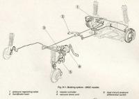
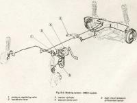
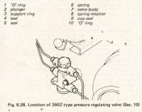
Here are a few drawings showing the location of the "Pressure Regulating Valve" and the "Dual Circuit Differential Pressure Switch" for the two different systems. For the system with the PRV and the DCPDS located in the engine bay, Fig. 9.28. it appears that the PRV is mounted on the firewall, under the throttle linkage and adjacent the Brake Booster/Master Cylinder assembly. It does look like it has two mounting holes doesn't it, but only one is used:ermm: The DCPDS is mounted on the inner fender wall.
-
Engine running extremely rough
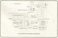
Can't help with wire colours but here is a diagram of the solid state ignition system which may help: -
-
Master cylinder rebuild
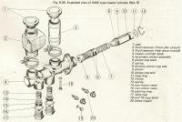
Assuming you have located and removed the two STOP BOLTS, #18 and #19 in Fig. 9.20, you can get the piston out by using a GENTLE application of compressed air to the front port. A bike pump will probably do it, just make sure the other end of the M/C is covered over with a rag to arrest the projectile once it starts moving.
-
Instrument Light Bulb
Just be a bit wary of using a higher wattage bulb, even a 4W over a 3.4W. The extra heat generated may just be enough to trash the lenses in the instrument binnacles. They will probably be very fragile after all these years. Using LEDS will minimise this possibility and introduce a measure of robustness over an incandescent bulb. http://www.narva.com.au/Globes_7.html You can also get silicon rubber condoms to personalize your dash illumination. http://www.narva.com.au/Globes_9.html
-
Vacuum Advance response on Dizzy
What exactly did you re-build? I have found that many distributors have got square ball bearings under the vacuum advance plate when they should be round. The entire assembly needs to be dismantled, cleaned, re-greased and perhaps you need new balls as wellLOL Once all this is done, the plate should react well to mouth suction on the vacuum motor, hence the expression, "Suck it and see":nervous: Just be careful when you remove the circlip underneath the points plate, bits will go everywhere if you aren't ready for it:tapemouth The vacuum motor may also be leaky so bear that in mind.
-
Tie Rod Ends
No, I wouldn't advise using heat, it shouldn't be necessary. If they are the originals what makes you think they need replacing:cheeky::cheeky::cheeky: You might consider getting new lock nuts too, just in case you trash the old ones when you undo them:ermm:
-
Tie Rod Ends
The LHS [drivers side for a LHD vehicle] is a Left Hand Thread. The Tie Rods have a flat cast into them adjacent the locknut. Use a 22mm open ender on the locknut and a crescent or pipe wrench on the cast tie rod end flats and turn in opposing directions. I sometimes think that Wheel Alignment Technicians have an evil sense of humor when it comes to tightening up these fasteners:mad::mad: Perhaps they should sometimes be downstream of some of their own handy work:devious::devious:
-
To our friends in Oz
The TRAGIC part of this accident is that the convoy was, allegedly, allowed through a road block, into the inferno! Survivors and friends and family are not at all impressed:tapemouth
-
Gauges and Fusebox mystery
The big red key is for a BATTERY ISOLATOR which is a requirement for racing. You'll definitely need that turned on to do any fault finding:nervous: It is probably best to connect the fuel pump power to some sort of safety switch if it isn't already. If the engine stops for whatever reason then power is cut to the fuel pump to avoid feeding a possible fire. Race cars usually have this fitted. It can take the form of a pressure switch attached to the engine oil gallery so that if the engine oil pressure drops suddenly, e.g. collision/rollover, then the fuel pump power is cut.
-
...yet another Pertronix thread!
You are correct, the BR is primarily there to protect the 1.5ohm coil from meltdown when the engine is running. It was just something I noticed in the wiring diagram, removing the BR applied full voltage to both the coil and the tacho. As I mentioned above, for an impulse tacho. it may not matter at all.
-
lead filling
My advice would be to avoid using lead filler, at all costs:finger: The health issues associated with lead working are too nasty to warrant using it. If you are comfortable with plastic filler then stick to that [pun intended]. You can convert a flat hole to a depressed hole with a ball pein hammer. It doesn't have to be very deep, only a mm or so. Back it up if possible with a small tube like a socket so that the depression doesn't spread too far. You can also apply a dob of filler behind the panel to give it a decent area of adhesion. Just prepare the hole like you always have, bare metal, scoured clean then apply the filler. Make sure you can paint the filler, front and rear, to prevent it from absorbing moisture.


