TomoHawk
Free Member
-
Joined
-
Last visited
Everything posted by TomoHawk
-
 Thanks, but that guy's data doesn't make sense, and he says it's not correct, especially for lambda=1. He gives 0.33V for lambda=1.0 but it should be about .45V . Then says he used a wide-band controller to get measurements from a narrow-band sensor? He also needs to change the way he explains the theory of the sensor, as he says the fuel "pulls oxygen through" for both rich and lean conditions. That's why I passed this page the first time I viewed it.
 -
I would like to build an AFR meter using an Arduino board, and I would like to know if anyone has a detailed chart of voltage v AFR for a narrow-band oxygen sensor. Yes, I searched for a long while, but you guys usually have useful engine data. There are lots of chart images, but they all look like a curvey Z, so obviously, there isn't enough detail to pick out coordinates to plot in a spreadsheet. If I had a chart or table with enough detail, I could generate a formula or a lookup table. The former would be better. It's just too bad the LCD displays are monochrome, because colour would be easier to interpret while driving, I suppose I could add some colored or RGB LEDs. thxZ
-
This sounds like a good Arduino project. The thing would pulse the injectors using 12V and a MOSFET. You could add a momentary pushbutton to start a single cycle, or a toggle switch to start continuous pulsing. Otherwise, I'd probably put some leaner through the injectors with light pressure or gravity-feed. if you set up a glass reservoir and recycle the cleaner, you could see when they are un-stuck or spraying well, then have your work pay-for itself by cleaning injectors for others. ? FYI- I've been told by a few "technicians" that you can't clean injectors- you must replace them. ?
-
You need to add 10 to whatever number people are usually using, because Mr. K came up with the idea for the Zed in 1959! Or you need to be specific to reference the anniversary of the first American sale.
-
The important thing for installing a flex fan would be to know the correct length of the spacer and the correct diameter. Auto parts stores are NO help; they ( their computerized parts systems) only have parts (original or compatible OE replacements) for new cars, not "old" cars, and they don't recommend putting compatible parts on cars, even if you know it will work. I couldn't get an ignition coil condensor for a 1969 Camaro or 1967 Mustang. I was told to contact the manufacturer or visit the car dealer. Can you balance the space or the fan?
-
Measuring the coolant temperature is easily done with a temperature sensor like a thermocouple or the LM35 temperature sensor. The Lm35 gives a signal in millivolts proportional to the temperature in degrees C, and you can make an offset circuit for it as well, because 0C related to 0.5Volts, or display it directly using an Arduino program. Is there a practical electronic sensor for intake manifold vacuum. That's also important for having the engine work efficiently.
-
Because using an oxygen sensor as the sole sensor for the Air-fuel ratio is like measuring tyre pressure using the temperature of the rubber tyre.
-
You are right, about the use of the multi-sensor setup, and how it's all used to get an "average" or overall fuel mix that works reasonably well, and it agrees with my opinion that just the one sensor can't do the whole job. It makes you wonder why so people put their whole confidence in just the one sensor, how there's a whole aftermarket industry that makes a LOT of profit on it.
-
They also have more than just the one oxygen sensor, in a few places, and modern electronic or digital engine controllers that make up for sensor degradation and other compromises. I see no reason why you can rely on only one oxygen sensor. to get an overall and precise air-fuel mixture determination.
-
That theory is well known, but presumes you have an engine that is working 100% perfectly and you have a 100% perfect combustion.
-
Well, since you are infinitely knowledgeable in gas analysis, explain, exactly, how you convert an oxygen signal from a narrow-band sensor to an air-fuel ratio.
-
I agree with that, for the most part. It's just that people buy a narrow-band, or wide band gauge and the corresponding OXYGEN sensor, and set it up, thinking they will get Air-fuel mixture readings from the exhaust gases.
-
That's too ambiguous to answer.
-
The point is that people claim the sensor/gauge combination give an accurate and precise measurement, which it can't. It's based in faulty presumptions, and the engine is controlled by high-speed electronics to get an "average" that just happens to be acceptable. You might as well measure the AFR from the temperature of the tyres. Or, you might as well make the claim of a "clean-burning fuel," when the sole purpose of the internal-combustion engine is to burn fuel to create carbon dioxide and water, and nitrogen compounds. Until a sensor that directly measures the air-to-fuel relationship in the intake manifold, you cannot claim to measure the air-to-fuel ratio by the waste gases of combustion.
-
I think what I'd like to see is scientific PROOF that you can quantify the FR in the intake manifold be measuring the oxygen in the exhaust. Just because lots of people use it (either the narrow-or wide-ban sesor and AFR gauge) doesn't mean it works and is accurate and recise.
-
That's the advantage of a simple display like this: to see if there is a pattern in the exhaust for the different throttle settings. It should be an overall steady value until you press the throttle pedal enough to operate the TPS, then you ought to see the display change to a slightly lean indication for mid-throttle, then richer for an open throttle, then back to rich at idle. If your AFM and ECU are operating correctly, the display should be fairly steady otherwise.
-
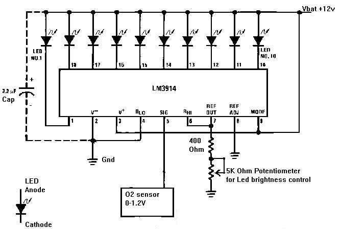
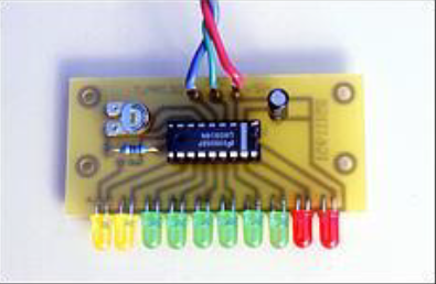
You may be interested in this inexpensive thing, to try for fun. DISPLAY FUEL MIXTURE MODULE EGO 10LED
-
The problem is that an oxygen sensor in the exhaust stream can't tell you what the fuel mixture in the intake manifold is, precisely. You make a LOT of presumptions, and people accept what the gauge says as an exact, scientific answer. You can buy pre-built displays cheaply from electronic kit companies, but it's just as easy to build one yourself, if you have the skill. Because the signal can change quickly, you would be better off color-coding the voltmeter, for rich, about-right, and lean.
-
Tjereis no "calibration" needed. You install the oxygen sensor in the exhaust pipe and hook it up to the gauge.
-
If I had a bit of brass sheet (about 2.5mm thick) I think I could make the part. It looks like a U. The turn signals weren't engaging too well, I think because the spring in the switch which presses the brass part against the contacts, was weak. Do you know what's inside the dimmer switch? It'll help to know if you take the cover off. I could dowse that as well. DeOxit 5% has the cleaning/deoxidizng chemical, plus a kind of lubricant. A used one goes for $100 on eBay, and ZCarSource "rebuilds" them for $200...
-
I have an L28E with L-Jet EFI. I was thinking of building an AFR (air-fuel ratio) gauge using some common electronics stuff. It lights up LEDs from a signal generated by a narrow-band oxygen sensor in the exhaust pipe. But, I question the legitimacy and accuracy of the gauge. How does oxygen in the exhaust tell you how much air and fuel is going into the cylinders? There is no sensor that will do that, and it would go into the intake manifold, not the exhaust pipe. The best you can do is to use a modern engine, with a programmable controller to measure the air (via the AFM) and calculate the amount of fuel inject from the fuel pressure and the injection timing, then calculate the AFR. Measuring the oxygen in the exhaust does not tell you what is going into the cylinders. The best you can do with that method is to guess at what the AFR is, with presumptions of engine perfection (you would need an engine that is perfectly built, in perfect operating condition, producing a 100% perfect combustion of what did go into the cylinder.) So using one of the so-called AFR meters is a bunch of hooey, and the value it gives you cannot be trusted. Using a narrow-band oxygen sensor, the signal will jump around, from a relatively lean (say 15:1) to a relatively rich (about 12:1) mixture- IF you believe the theory of these sensors. It's logical to say that the amount of oxygen detected by the sensor, is proportional to an amount f air, but it cannot tell you the AFR. It only tells you there is oxygen/air in the exhaust. I have read a lot about wide-band sensors, but I'd say it is the same as any other oxygen sensor. The AFR display I will be building, if you are electronically-skilled, is based on the LM3814 LED driver chip, and lights LEDs, linearly, in proportion to the signal. And the best you can do is to adjust the mixture so the display moves around enough to get an "average." then do some on-road or dynomometer testing to get your desired mixture. Or, you could use an exhaut gas analyzer to adjust the mixture based on theCO content, whic is similar to the oxygen content adjustments.
-
Meanwhile, the turn signal switch had broken; the brass piece of metal in the switch which moves to make the contact had worn so much that it was broken. I don't suppose anyone has a spare? Other than that, I think the dimmer switch probably needs to be cleaned.
-
Nissan also names a driveshaft, what most people call half-shafts, and the driveshaft is called a "propshaft." The dimmer switch is sometimes called a combination switch because it's a combination dimmer and turn signal switch. Maybe if you refer to each part (i.e., turn signal or dimmer switch) of it instead of giving it a more general name is better.
-
So... I removed the high-beam switch from the car to test and clean it on my workbench, and the thing was stuck on high-beam. Even if you switch it to low-beam, when you probe the switch terminals, it's still on high-beam. You can send the switch to ZCarSource, who I believe owns what was left of MSA's inventory, and along with their machining and technical department, can rebuild your turn signal/high-beam switch for about $200. I bought a used switch from an eBay seller, and hopefully it will get the car to a working condition for another year. Rod's Datsun Parts in Los Angeles will sell you a used switch for $300, so I'd rather have a used one rebuilt. Other than that, you will have to eventually retro-fit an antique or aftermarket turn signal switch with a high-beam function. Fortunately, the connections to the main wiring isn't that complicated.
-
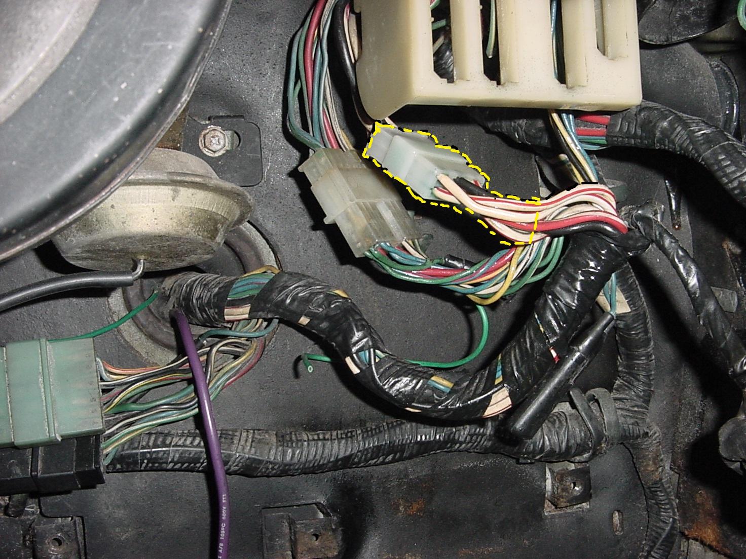
I finished the work on the headlamps, and I think they are brighter now. I cleaned (de-oxidized with DeOxit 100) the large C-9 connector by the junction box, and the connectors for the beam switch, and the multi-pin connector- both underneath the steering column. They had showed some black stuff on the plastic around the (round) pins, which I think might be from some overheating. But after de-oxidizing, thee pins were brighter, so they should not get so hot. Here is a photo of the C-9 connector, highlighted in yellow.