


TomoHawk
Free Member
-
Joined
-
Last visited
Everything posted by TomoHawk
-
 I have read some SCCA regs on what's required to go on a helmet, such as putting your name, birthdate & blood type on the back, and the safety sticker is supposed to be there, but I haven't been able to find any regs on what, if anything, goes on the suit. I would suppose a patch with your name goes over the left chest (pocket) and one with your team affiliation, if any, probably on the other side (pocket.) ad the SCCA patch, for SCCA licensed racers. Is there Anything else that's truly important/required? If there are any regs, please tell me where in the GCR to find them.
 -
That explains a few things about you now, also...
-
It gives a new mean to a "painting party",,,,,
-
I would like to paint the inside of the garage; specifically, things like the doors, woodwork, and anything you might touch with dirty or oily hands, besides the workbench and plastered walls. Sometimes I even get soot on the garage door if I start the car before opening the door. I would like opinions or experiences with paint that can be cleaned with household cleaner, ("awesome" cleaners, dilute SimpleGreen, etc.) My preference is satin or gloss white, as the place is brighter at night. I considered washable latex, floor/patio paint, and even epoxy garage floor paint.
-
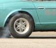
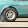
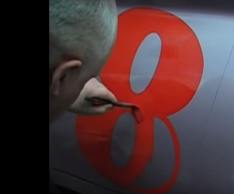
What does the number matter? I'm used to see the 46 in the photos, but the car number is only for scoring. Gone are the days when the official number-painter-guy painted on the number just before the race.
-
IIRC, the fund raising effort almost reached the $85,000 goal, and the owners put in some more.
-
I selected the Black & Mild with a wood tip. I also plugged the hole in the tip, because I don't care for the taste of raw tobacco any more. I still end up spitting a lot tho; apparently the flavour still gets through to get the 'juices' going. It still takes a bit of discipline to drive with the thing in your mouth, without letting it fall out as you look around or do things. So you can practice your 'cigar grin' whilst you look classy and drive your classic sports car.
-
Remember the 2013 effort by the Bonk Brothers to give John Morton another try to win the SCCA Group E race? Well, the #48 car is for sale:
-
The dickies jumpsuit ended up looking like an Italian janitor. a jogging suit would look better, but those are all make of synthetics. How about tobacco products? The old racers might have a pipe, if you were a jaguar guy, or a cigarette, or a thin cigar, depending on your smoking habits. Are there any tobacco aficionados following this thread? Somebody gave me a couple cigarettes last fall for a weekend trip, but the cigarette quickly got limp and fell apart from the humidity (it rained.) So that leaves the pipe or cigar. I don't think many Zed drivers would go out in a wool or tweed jacket, so that leaves the cigar. Which would be the most "appropriate cigar to bite on while you drive? Something thin and not too long I'd say...
-
That's why I took the time to put together a buzzer with a blade terminal and a ground clip. It's quieter than the horn. I also use it for probing the other connectors. Don't forget to use the grease they give to to lubricate the copper ring and the button. The fun thing was to get the right hole for the pin that turns the turn signal off, and to get the wheel on so it's centered wit the wheels.
-
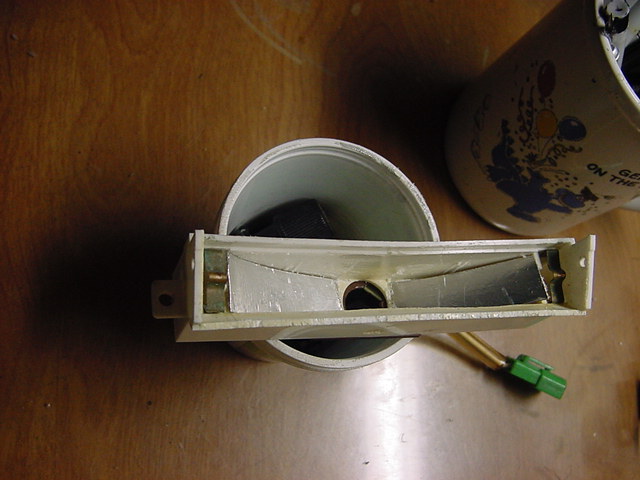
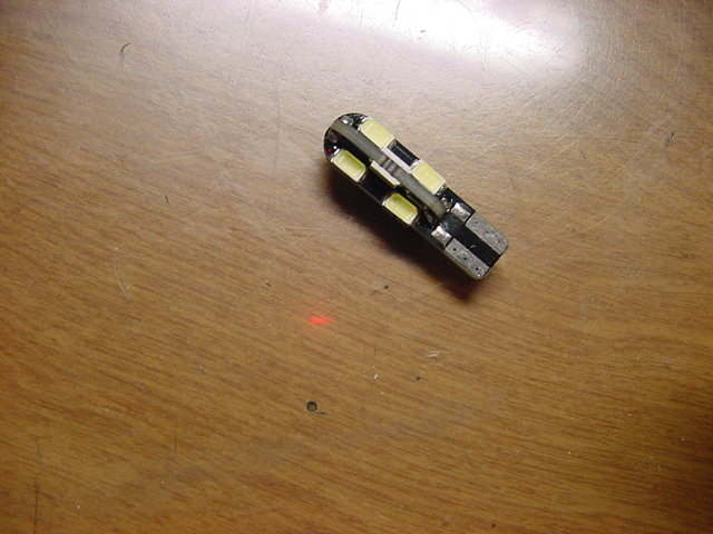
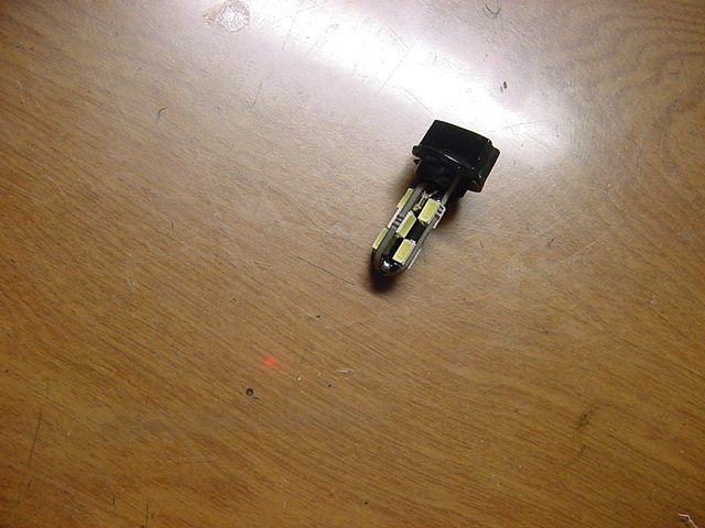
I finished my LED bulb upgrade for the map lamp. First I cut strips of thin plastic (the kind you get from stuff packed in the welded plastic display packages) to fit into the lamp. The strips were covered in aluminum foil tape (used for taping heating ducting) and were glued into an arc to form a reflector for the light. I used GOOP for the adhesive. The bulb used is a 12 emitter paddle-style bulb with 100 Lumens output. The reflector and high-output bulb made a noticeable difference in the light. I might still put in a bulb of the warm-white 5500K color, but for now it is fine. I did not paint the inside of the lamp with gloss white paint, but I might later. I like what I did because I will not have to disassemble the lamp to change the bulb.
-
I have ordered some odd-looking relays via eBay recently to see what they are like and how they would work out. Both are the 4-pin type. One is a "waterproof relay" that comes in its own shell, and the other is a relay with an integrated blade fuse. What I'm interested in knowing is that for the former relay, is it practical? The the base has the terminals, the cap has the relay inside, and you plug them together. For the latter, would you trust it to work if mounted on the inner fender? It looks like the socket where the fuse goes would be most likely to collect water and eventually corrode. If not, this relay would make it convenient, as you don't need to wire in a fuse holder too. BTW- they are all pictured with the metal mounting bracket, but when I asked about it, I was told you don't get the bracket! I suppose you could make one, but it wouldn't have the small knuckle that keeps the relay from slipping off, unless you can figure out how to put one in. Opinions?
-
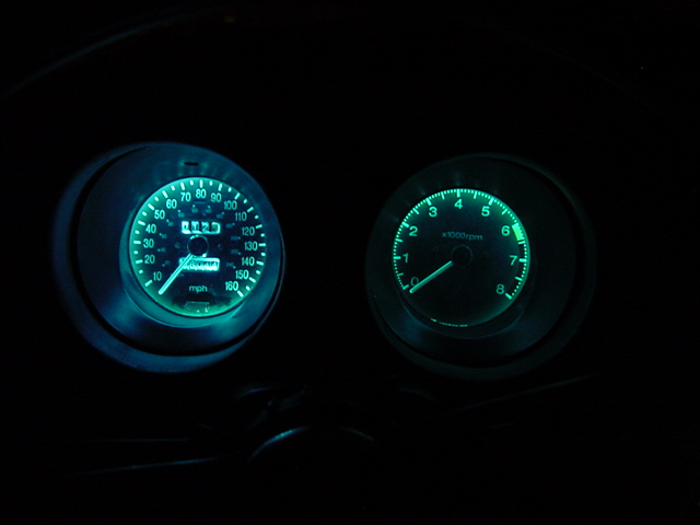
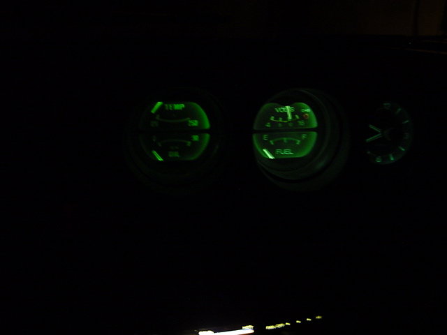
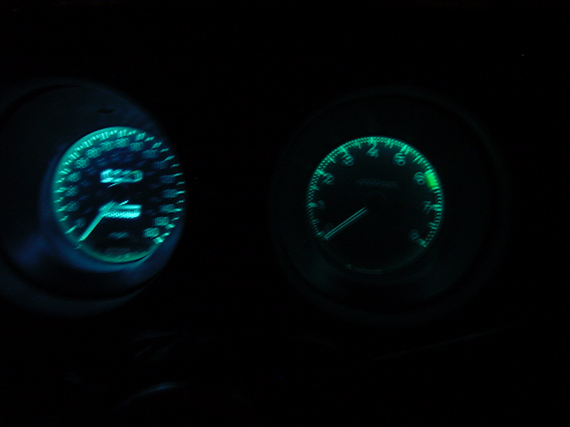
I have had a couple of nights driving with the LED gauge illumination, and I can tell you how nice it is to be able to see the gauges in the dark. The center gauges are less important compared to the ones in front of the steering wheel, and now I can read them all. The speedometer is easily read- even the odometers! And the other tachy is easily seen, even though you don't really need to tell the exact reading. So I think I can conclude my gauge illumination upgrade project, write it up for myself, and move on to the next thing. I appreciate the inputs and comments from everyone.
-
They use Corby rivets and tubular ones. I saw a video of a guy riveting to strips of wood together using just some brass rod. It's odd to see the chainring bolts there, which are commonly used on bicycles, but still very useful If I had enough time ( if I had thought of this last Christmas) I would probably have enough time to drill out the rivets and put in something better, but I'd like to finish working on the thing and enjoy the out-of-doors. As for the finger joints of my wood steering wheel, they are strong joints, and were used on steering wheels since the earliest days of the automobile- even without the metal frame.
-
I disagree on all those points. The wheel is almost new, is not meant to be covered with anything, and only needs to be dressed. The expensive stuff you see on eBay is vintage stuff from an old sportscar, inappropriate for my use, or some artisan trying to get rich making replicas.
-
What if you drilled out the cheap rivets used to make the wheel and replaced it with screws like this:
-
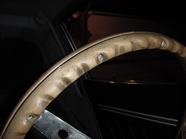
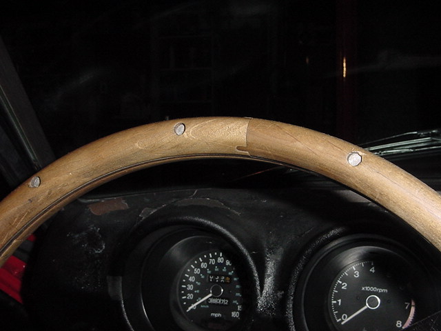
I agree. I looked at some old steering wheels on eBay, and aside from the $2,000 - $16,000 cost, they looked nice and gave me some ideas: For the front, I would polish what is showing and put a drop of epoxy on the rivet in such a way as to make it look or feel like a raised head of a rivet. For the back, I would like to fill the hole with a brass rod or a brass screw glued in, and grind, shape and polish it to look nice & smooth. Maybe I can even countersink it into the wood. I will see what the hardware store has for brass fasteners with 5-10mm diameters. Apparently, they just used brass rod for the rivets and hammered them down to make the mushroom heads, then smooth the heads with filing or sanding. Other than that, it should not be stained, but left natural, and the only coloring it will get is from your hands or the Tung oil finish. Sorry, I lost my great-great-great grandfather's recipe for the special varnish that he got from some guy named Stradivarius.
-
The original steering wheel was gone 15 years ago. It was crumbling apart, and the PO had it wrapped in a faux leather wrap. Here are a couple photos of the front and back of the wood steering wheel. I think you could agree that it would look better if the holes weren't so deep- at least the ones on the back. The rivets are fine from the mechanical and manufacturing point-of-view, but not so from an aesthetic one. what can be done? From the Front and Back:
-
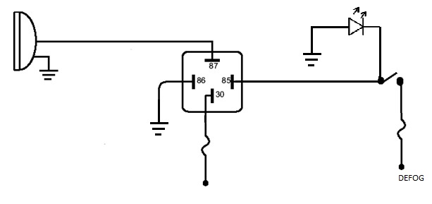
I found some good information here: http://www.bcae1.com/relays.htm It discusses many things about relays, including the coil resistance, and thus the current draw by the coil (of a Bosch relay) is ~160 mA (~75 ohm coil.) After looking at the cover of the fuse box and the wiring diagram, I learned that one terminal of the rear defroster switch connector goes to a switched ACC circuit of the fuse box. Since I'm not using the defroster, I will use that for a lighted switch and a hot wire to activate the relay.If I didn't have that, I'd use the bridged hot wire on the two relay pins and a switched ground. Now, the only problem is to get the right gauge wires in the right colors, and to assemble and install the wiring in a way that looks like a factory or period-correct way **cough!**
-
I think I found the answer on this web page: http://www.bcae1.com/relays.htm It discusses all kinds of stuff about relay, including the coil resistance and hence the current draw. For a Bosh relay, the current draw is about 150mA. After looking at the fox box cover and the wiring diagram, I learned that one of the wires going to the defogger switch is on the ACC section of the fuse box, so I think I'll use that for a switched hot lead to a lighted switch and a relay.
-
Most Internet tutorials show schematics where the relay for fog lamps or headlamps is activated by a switch that's connected to a switched 12V power source. You could also just bridge the 12V source to Pins 87 ( the relay contacts) and 30 (the coil) and go from pin 30 to ground with a switch in the cabin. The latter switched-ground method uses one less connection to the battery. But for the convenience of turning the lights off when you turn off the keyswitch or engine, you need another hot wire. My question would be, "where do you get the switched power from?" You could tap into the radio or heater power wires, but those two things use a good bit of power, and you wouldn't want your light going out on you when you blast the radio or turn on the heater. You'll need to know how much current as relay needs, so you don't overpower the +12V supply for the relay. What else is there in the S30 that you can tap into as a switch 12V power source to activate a lamp relay? Having 12V on a switch would also be good if you use a lighted switch.
-
Oh- for the OP, my Ep34 flasher makes a clicking sound. It's more of a relay-type click, not the kind from the bimetal contacts of the old thermal flashers.
-
If you could only convert the CANbus LEDs to non- CANbus, then you'd have a very large supply and assortment of bulbs. That is, if you don't mind having the usual load on your electricals, which is contrary to why you are putting in the LED bulbs, right? From the looks of it, the W5W bulbs, the 'paddle' type, or the ones that like like little circuit board, have a large resistor across the two contacts. It looks like you could just use your Dremel with a thin cutoff wheel and cut through the chip to break that part of the circuit. Maybe you could desolder it.
-
I was able to get some photos of the gauges in the dark. My camera won't adjust things like most smart phones do, so I tried some things myself. First, I adjusted the "EV" value to +2.0 which didn't do anything in the dark. So using what I can remember from the days of 35mm, I tried different shutter speeds like 8sec, 2sec, and 1 sec. 8 seconds was too bright, and even with the tripod, it was too blurry. 2 Sec. was still too blurry, though it was only hand-held.The latter (1 sec.) resulted in a photo you could make out. The two tachos were hand-painted inside with gloss-white paint. I also painted the back of the speedometer faceplate gloss-white. Most of the gauges and the heater panel have 24-emiiter BA9S LED bulbs. The clock has a 5-emiiter bulb, which I think I will change to a 24 next winter. It has enough light to make out the marks, but it's less important than the other gauges, so I'll leave it as-is. I also used a green permanent marker to color the LEDs. The heater panel LED wasn't colored so the printed colors of the panel show nicely.The electronic (PWM) dimmer is set to the lowest setting so that the LEDs are ON; any lower, and the lights are OFF.
-
I'm not too keen on the design of that panel, which uses the discreet LEDs. I wonder what the back oft he panel looks like- probably soldered leads and a bit of wire. You could make one that's much better without the hotspot the 9 LEDs will create, by using the SMD LEDs. An array of 20 or so would flood the cabin and probably blind you. Otherwise, if you are considering just a 194 LED bulb, you'll need a T3-1/2 or T5 size. T5 means it's a 5/8 inch diameter bulb, and you'll need to enlarge the hole slightly for a T5, but I think it might work, and the advantage of a T5 LED would be a greater number of emmiters. The T3-1/2 size will fit with no modifications. It's 40mm between the back and the front, plus about 5-8mm for the base. Also, avoid the CANbus bulbs for this application. I'm pretty sure the extra resistor on the CANbus bulbs gets a little warm, so we don't need that with the brittle plastic the map lamp is made of. Ultimately, a new design for the map lamp would be best,. The same dimensions would be fine, with at least 2 LEDs and a curved metalized reflector shape to the back instead of how the factory made them, with just an empty rectangular inside.
