
240dkw
Free Member
-
Joined
-
Last visited
Everything posted by 240dkw
-
 While at a car show this past weekend, had a very interesting conversation with a gentleman. His parents opened a Datsun dealership in Moose Jaw, Sask. The year was 1966, he said that the family home was on the same property and he grew up working in the shop. He remembers the day the Datsun Training trailers pulled into the yard and all of the mechanics spent a week going through the courses. He gave me three of these plastic bags, he says he has lots more Datsun stuff . I am working on getting a chance to go shopping through his collection.

-
That’s what I have, they are Kmart ones NIB I got a few years ago.
-
I always thought it was when they changed to the retractable belts that have the larger buckle assembly.
-
I will check tomorrow and let you know.
-
I am sure I have one.
-
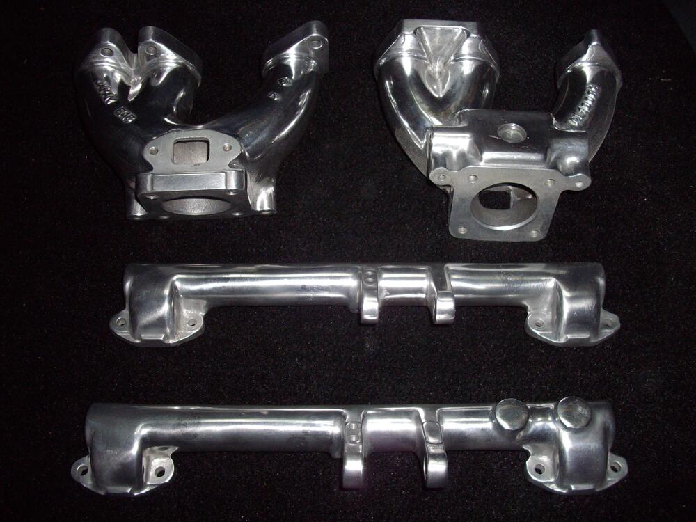
The non-emission style has only has two ports, one for brake booster and one for the PCV. The euro one has a third port. Also you can see a tapped hole in the right hand ear for the throttle linkage, which I think is for mounting the kick down pot, which the early ones do not have. Small differences I know.
-
By the way, all of the ones I made are based on the early non-emission style not the euro style.
-
I have done a few, some with the brake vacuum connection on the end and some with it on the top. Once you weld up the holes, to make it look good you have to go with the polished look and if you fill material is not close to the same alloy as the tube you will always see them as they have a different shine.
-
Sorry, you are right, that was a poor choice of words.
-
Ok that is wrong, the condenser on the point are needed to stop the points from arching when they are opening. You can run it without the condenser to see if that is the problem, but long term will cause heavy pitting on the points and failure. The condensers on the ballast resistor and on the alternator are for eliminating noise. No sure when you bought you condenser from, but I had three in a row all fail with in five minutes of running. They were from Rockauto (Made in China). Bought some from Napa(Made in Mexico) and still running strong.
-
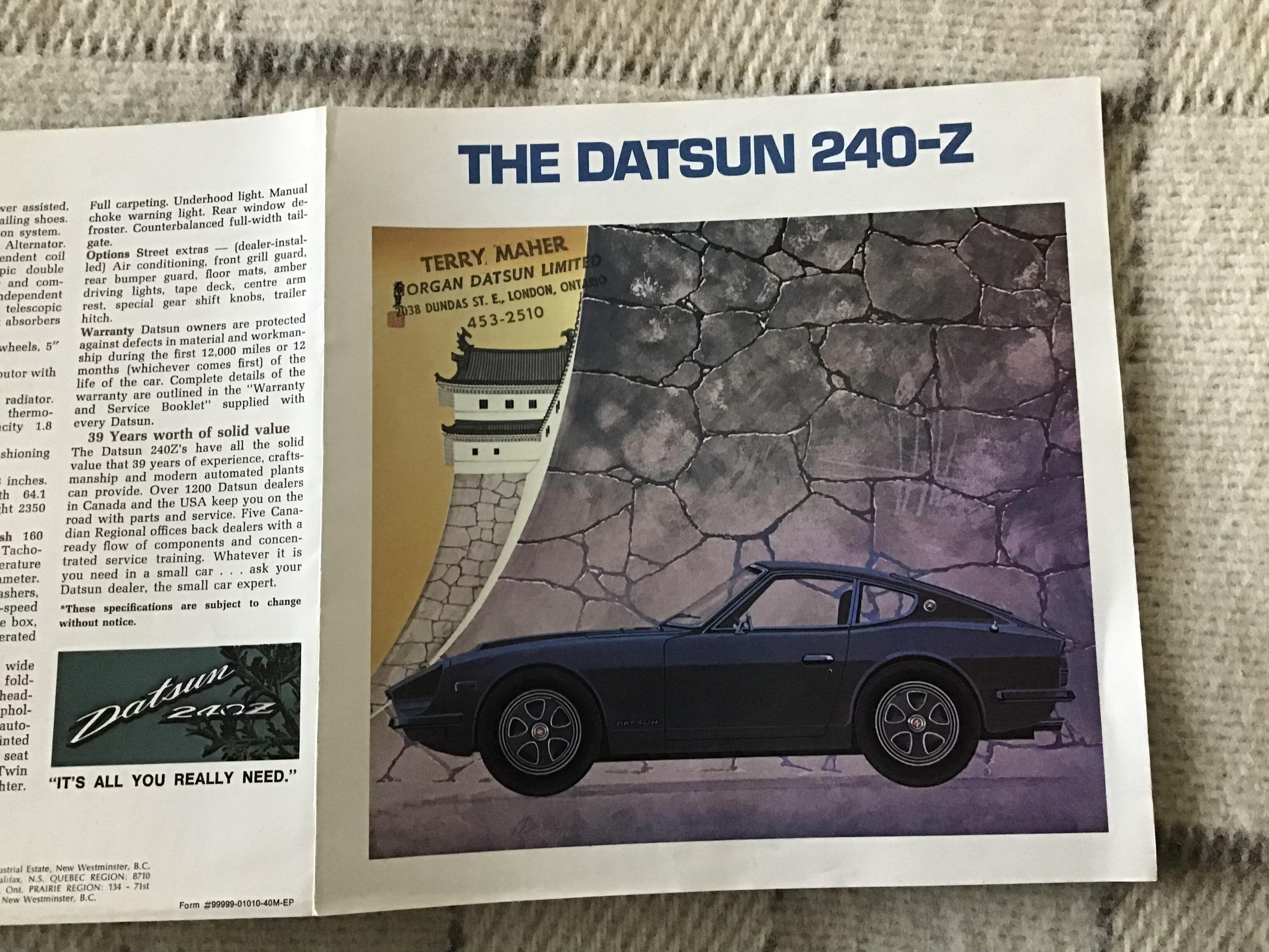
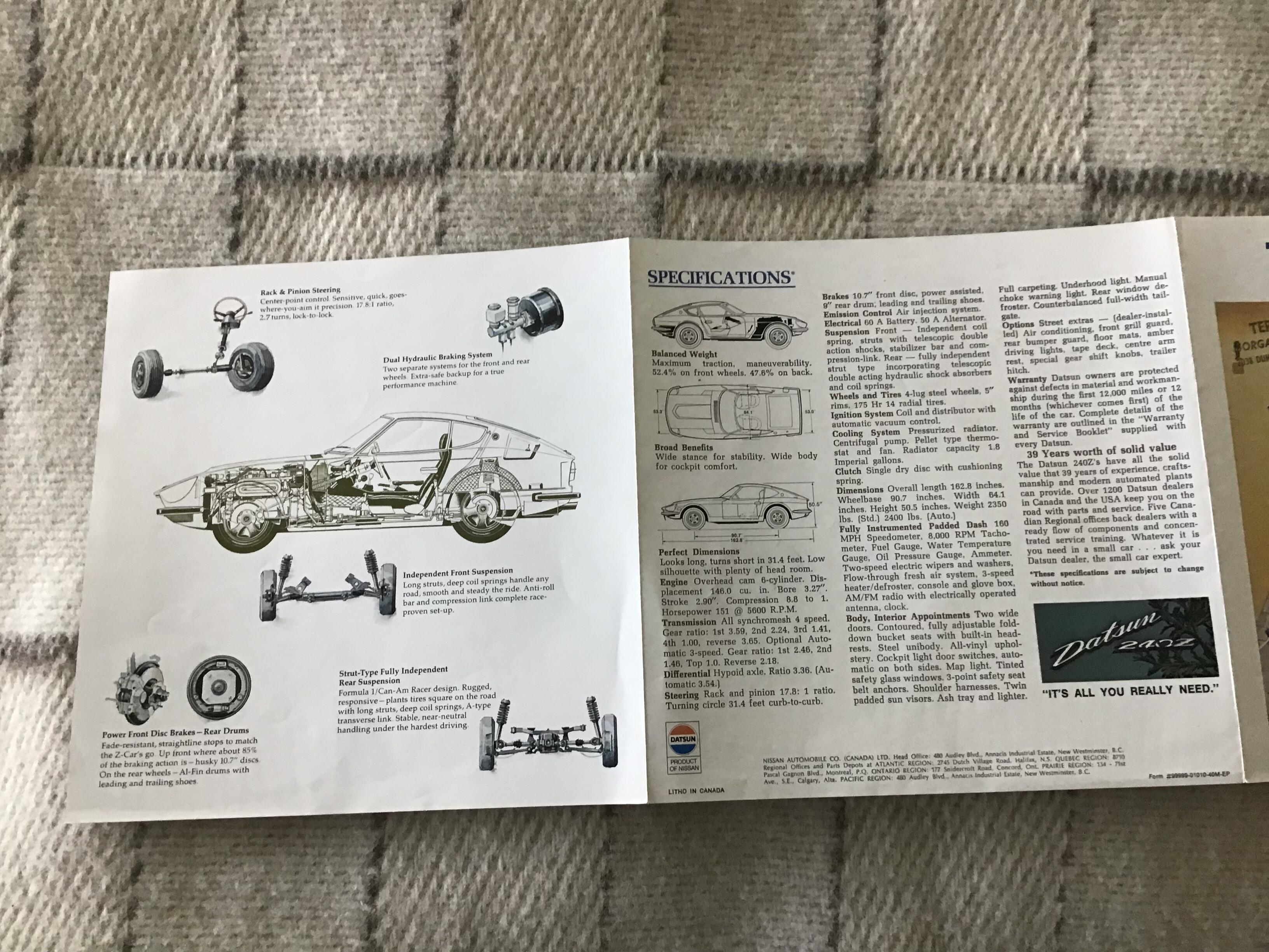
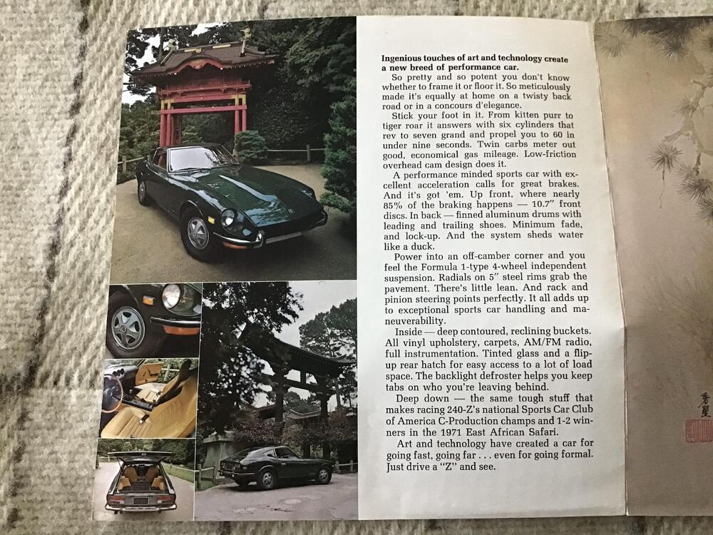
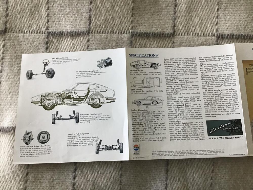
So there’s your answer. They did print the brochure in French for the Quebec market. @CanTechZ @Namerow
-
-
-
No, pick the one that allows you to make adjustments in both directions and call that one #1 cly
-
Yes that’s what I am suggesting, remember that the dizzy tang and slot in the oil pump shaft are keyed by having the two offset so they only fit together one way. And check that the points are working like Zed Head said in post 10. I can’t guarantee that will work but it is worth it to try. Don’t worry about the vacuum hose connection for trying it get it started.
-
I understand that, but the rotor,shaft and cam are independent of the dizzy body so by rotating one you are not rotating the other. You may get away with what you’re trying by aligning everything like Zed Head is listing but I am not sure you will have enough adjustment on the points to make it work. I still think that your points are now out of phase. Remember the only reason the vacuum pot was at the top is that someone probably wrongly set it up on the exhaust stroke instead of the compression stroke (which is a common thing) and over came this problem by messing with the plug wire starting point. So doing three different things to try and correct it may work, just not the way I would do it.
-
Flipping the mounting bracket did nothing for the alignment, if you don’t want to go through the hassle of dropping the oil pump, put everything back the way it was before, then do your TDC with the two lobes up, where ever the rotor is call that #1 and install the rest of the plug wires in the correct firing order counting counterclockwise and try it again. Again the bracket has nothing to do with the two shafts lining up, the way you have it now the rotor is aligned to #1 but the points are 180 degrees out of phase.
-
Still not understanding what you did, if you look at the picture that GredD posted the slot that the shaft of the dizzy fits into is offset, you can’t just rotate the dizzy 180 and put it back in. If you want to have the dizzy lined up as per the manual you need to set it at TDC on the compression stroke and drop the oil pump, Aline the marks and reinstall as per the manual. I think your sparking all of the cylinders on the exhaust stroke and will never fire that way.
-
I am going to go with, timing/compression. What have you done to get the dizzy in the different position? Your new photos show the vacuum advance pot in a different but still not correct orientation.
-
-
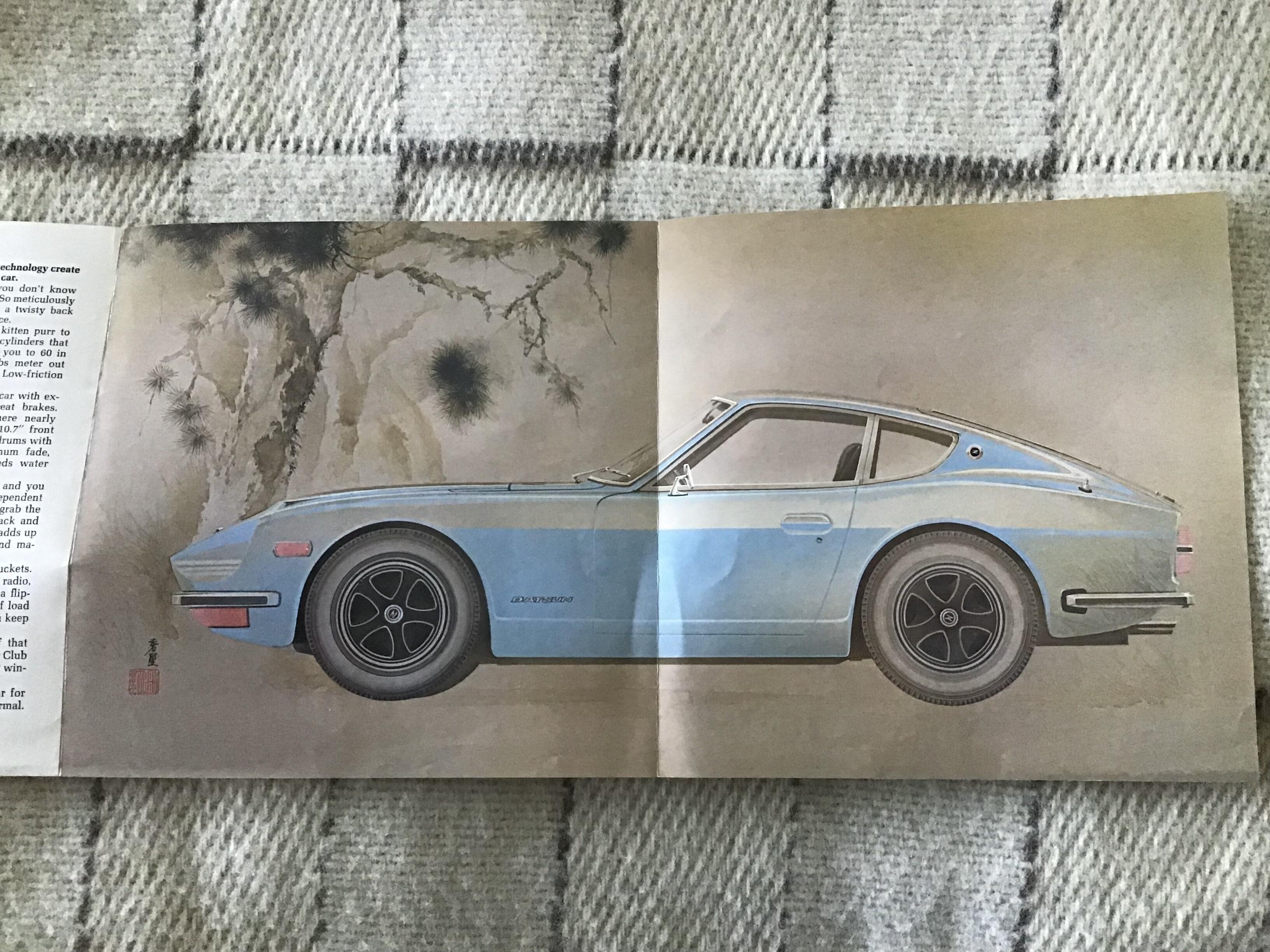
It is a tri-fold, so here is some photos, and the M is blended in with the Japanese writing. It is Morgan Datsun Limited.


-
Interesting, I did not know that some switches did that. But still if it is wired correctly you would have 12 volts at the coil while starting rather then the 8 volts through the ballast.
-
I agree, because his vacuum advance is at 12 o’clock. But did not want to go down that rabbit hole. Thought readjusting the plug wires was a better option.
-
As well, yes your distributor is in the wrong orientation, but just leave it like that. Find TDC on cylinder #1 on the compression stroke. Where ever the rotor is pointing install plug wire #1 there and do the rest in the right firing order counterclockwise. Fixing you distributor orientation is best left for another time.
-
OK I read you additional text and you will not get a spark while cranking the way you have it wired. You need to wire it with the powered b/w on one side of the ballast resistor and the g/w wire on the other side of the resistor and then the jumper from the g/w terminal to the coil +. I don’t know why you keep trying to do it different, Yarb even drew it out for you!