rv6aflyer
Free Member
-
Joined
-
Last visited
Everything posted by rv6aflyer
-
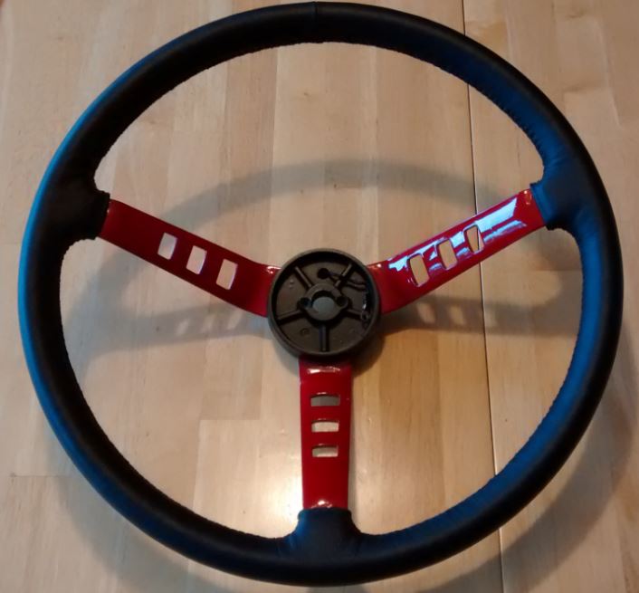
 I didn't do anything to the horn pad outside of cleaning it. I did have to sand blast the plates used to make the horn's electrical connection and then re-plate them.
 -
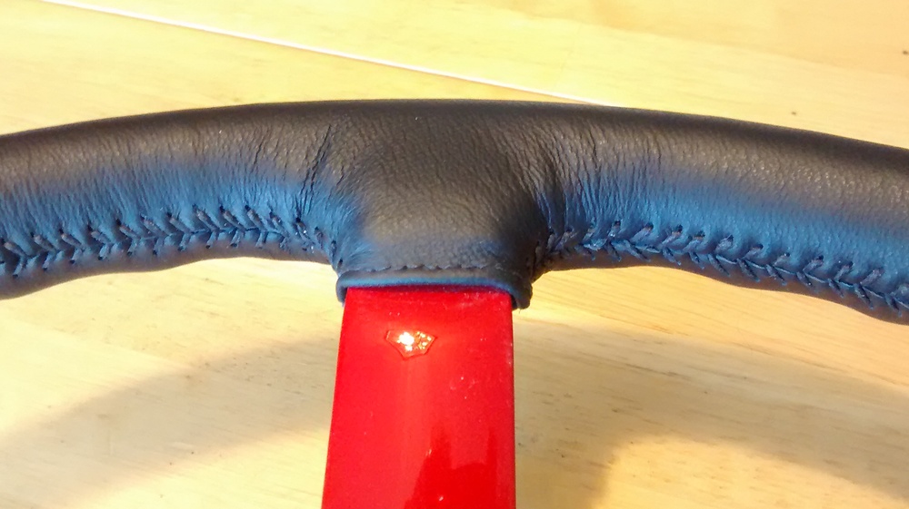
The final lacing only took a couple of hours, but I'm sure I have over 20 hours into this little project. But I enjoyed figuring out how to do the leather work. The materials themselves were pretty cheap. It was figuring out what to do and making numerous patterns to make sure the final leather cut would work that took the time.
-
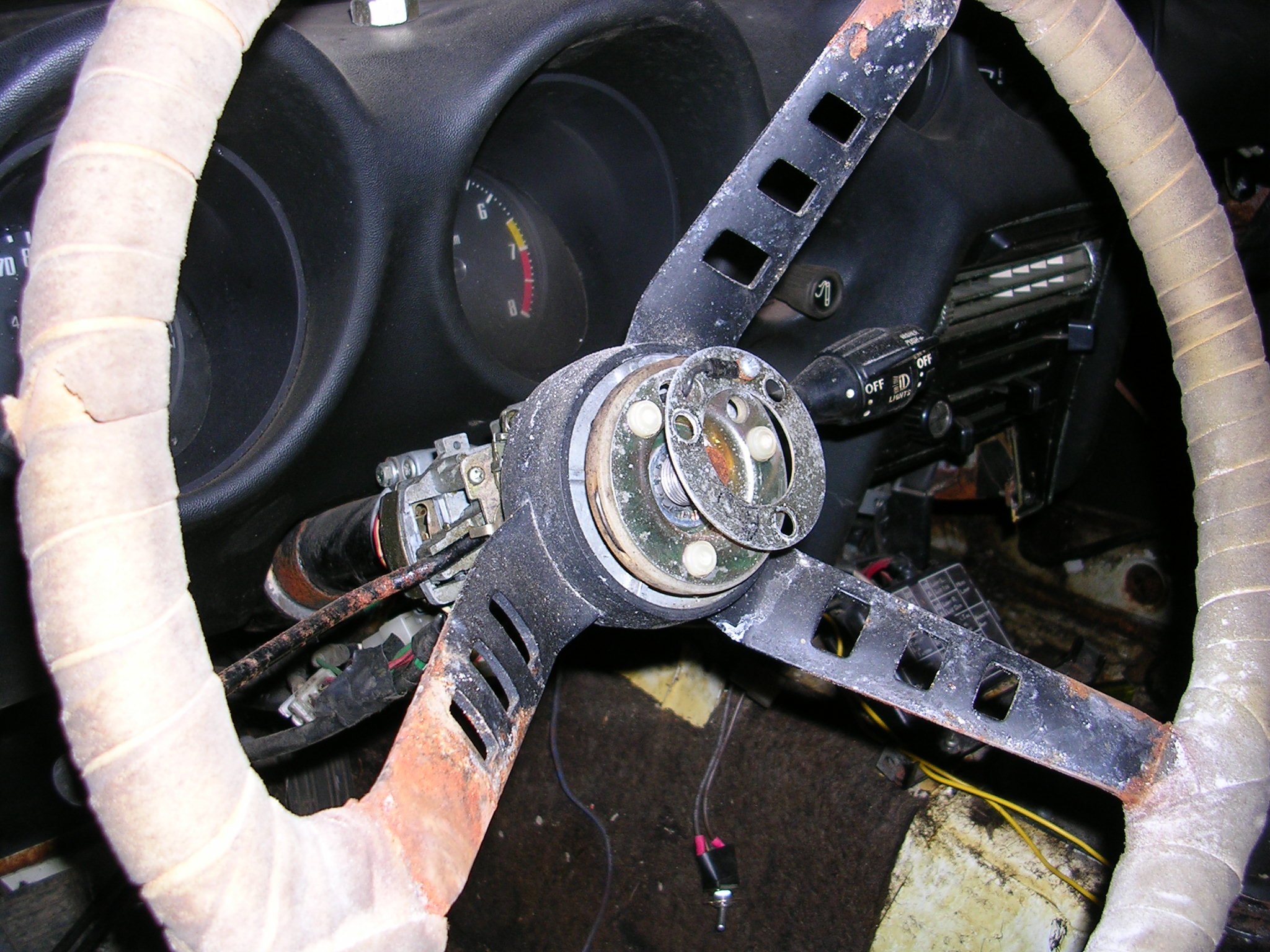
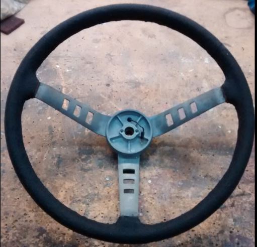
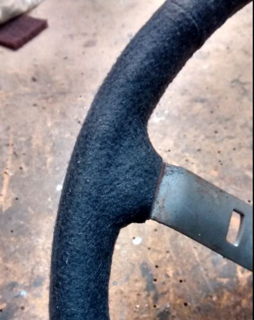
Here are some pictures showing my steering wheel makeover for my '72. I wanted something a little different but still keeping some tie in to the original rather than go aftermarket. The first picture shows what it looked like when I bought the car. Covered in some weird wrap and lots of rust. I wanted the redone wheel to be thicker so I wrapped two layers of felt around the original wheel to make it about 1/4" bigger in diameter. Finally, I wanted it wrapped in leather. I considered Wheelskins, but I wanted the outer part of the spoke to be covered as well. It took me a while, but I finally found a local place that sold leather remnants big enough to go around the whole wheel. I used some smaller pieces to develop the templates for the spoke areas as well as to determine the width I wanted. I made myself a little hole punch using brass tubing and punched all the holes. The lacing is RealleatheR craft lace which I bought at JoAnn fabrics. The spokes are painted the same color as the exterior of the car to put just a little pop into my otherwise all black interior. I spent waaaayyy too much time on this, but it IS a hobby and I'm pretty happy with the results.

-
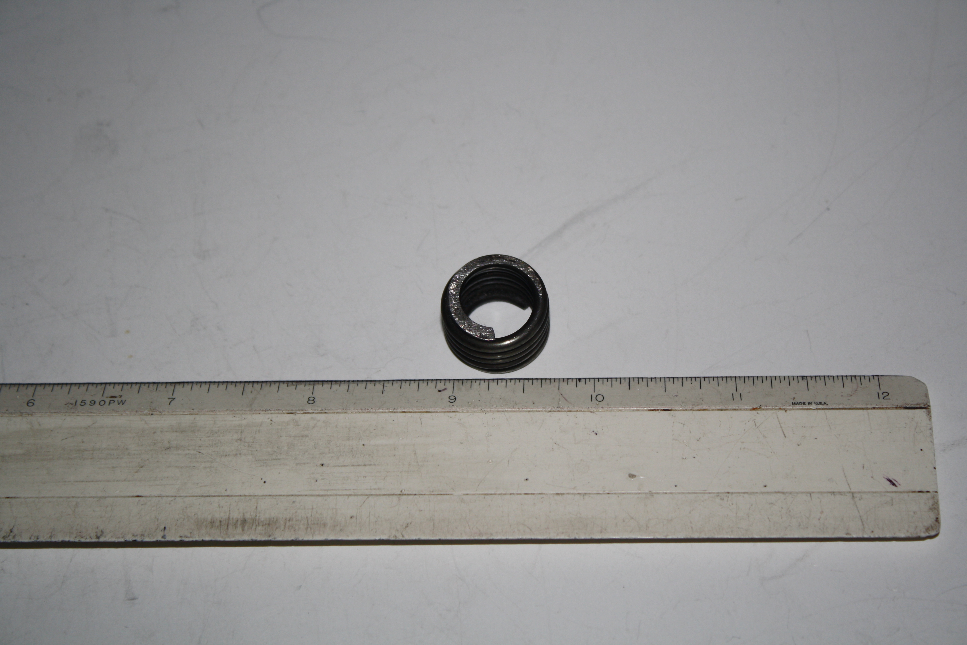
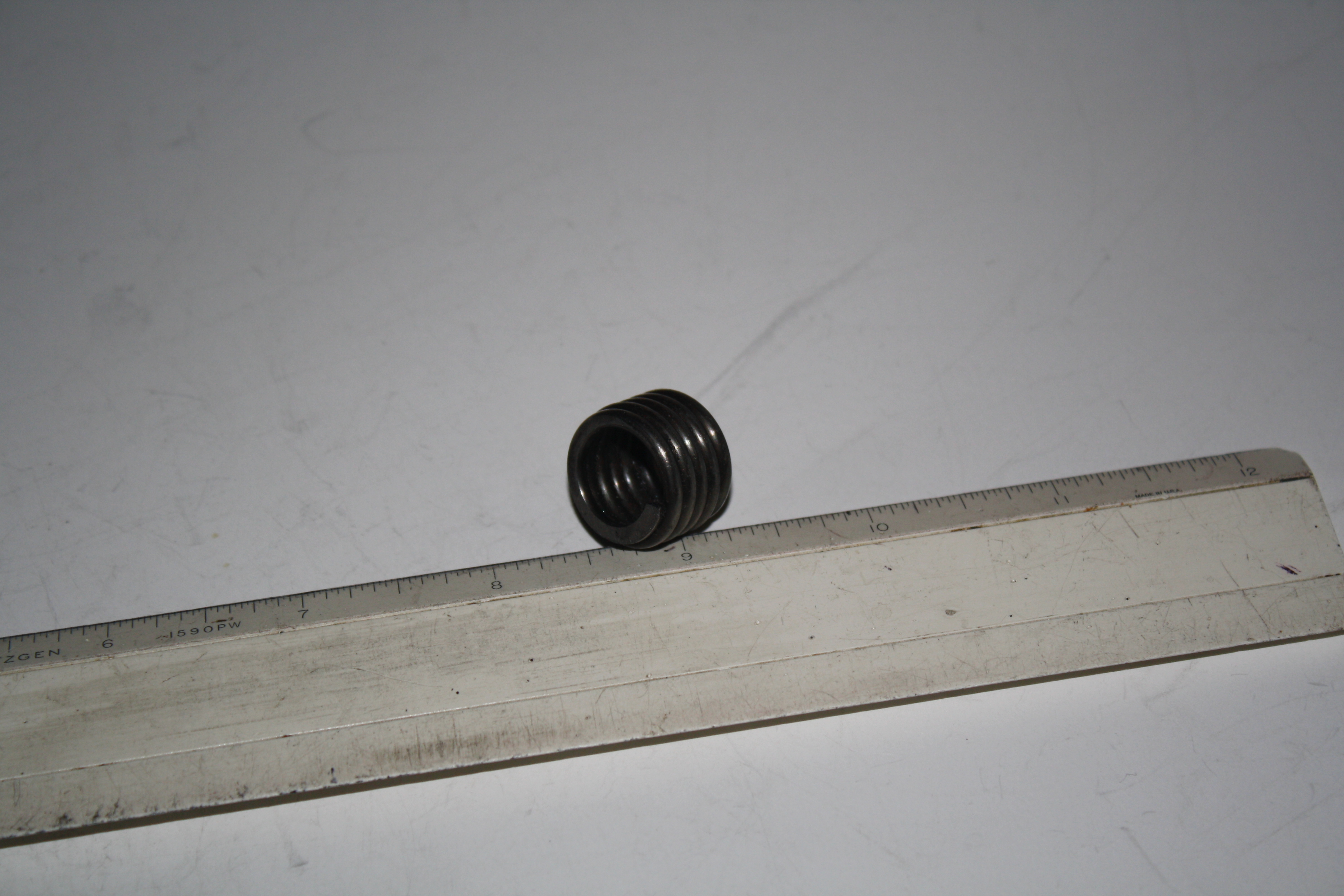
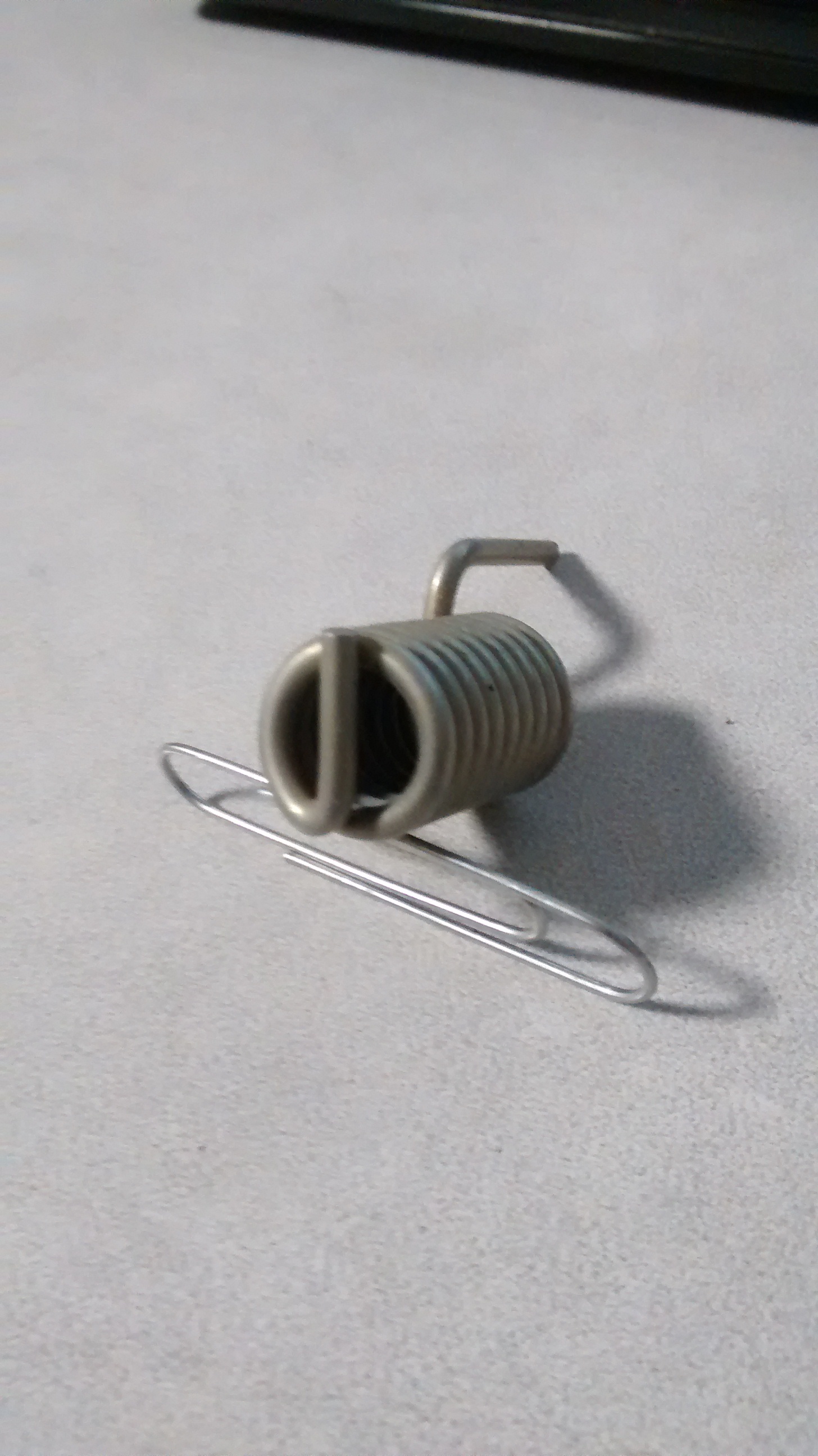
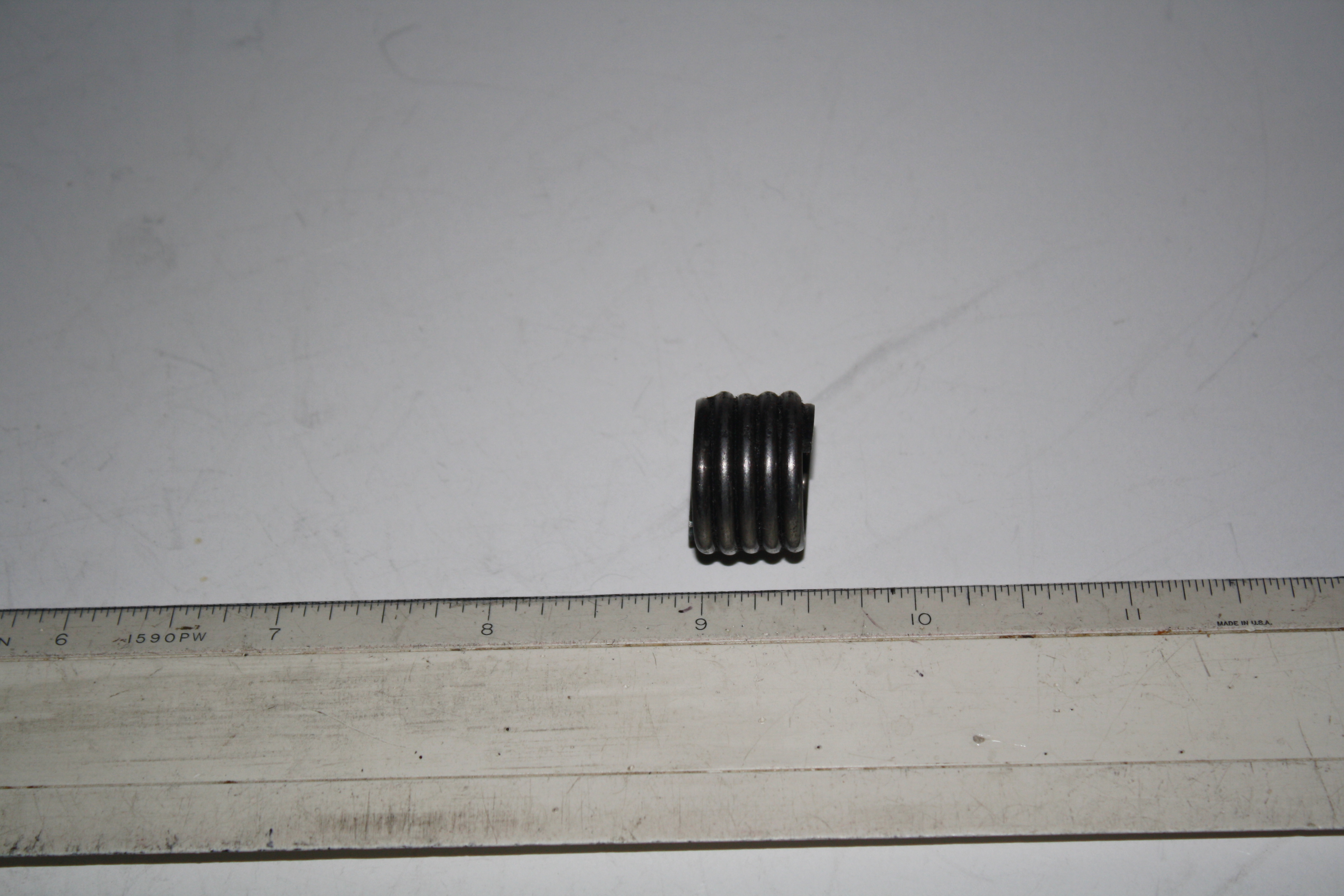
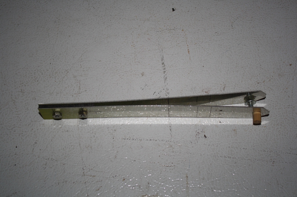
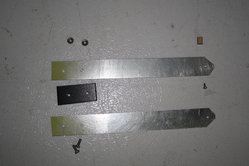
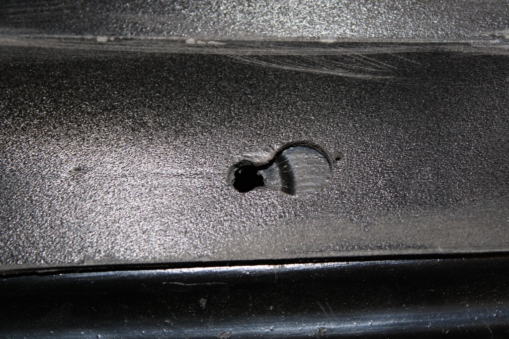
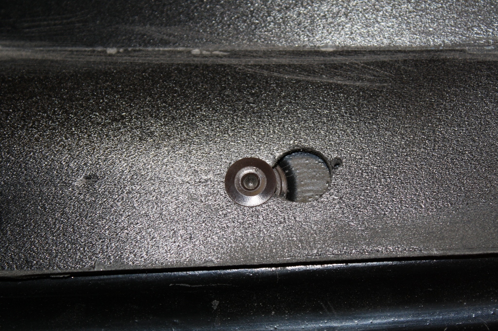
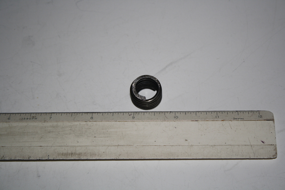
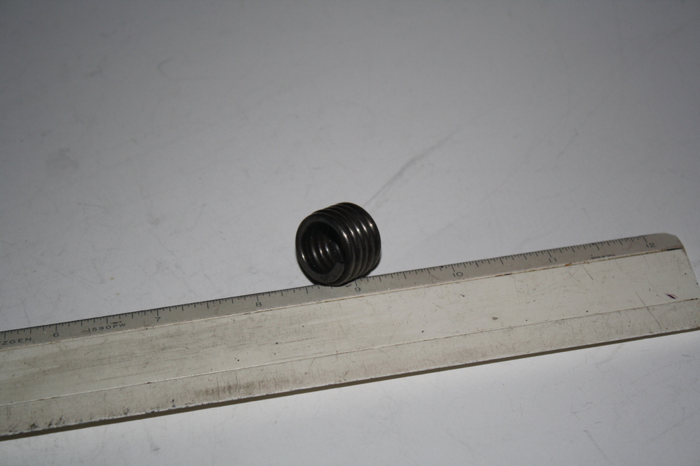
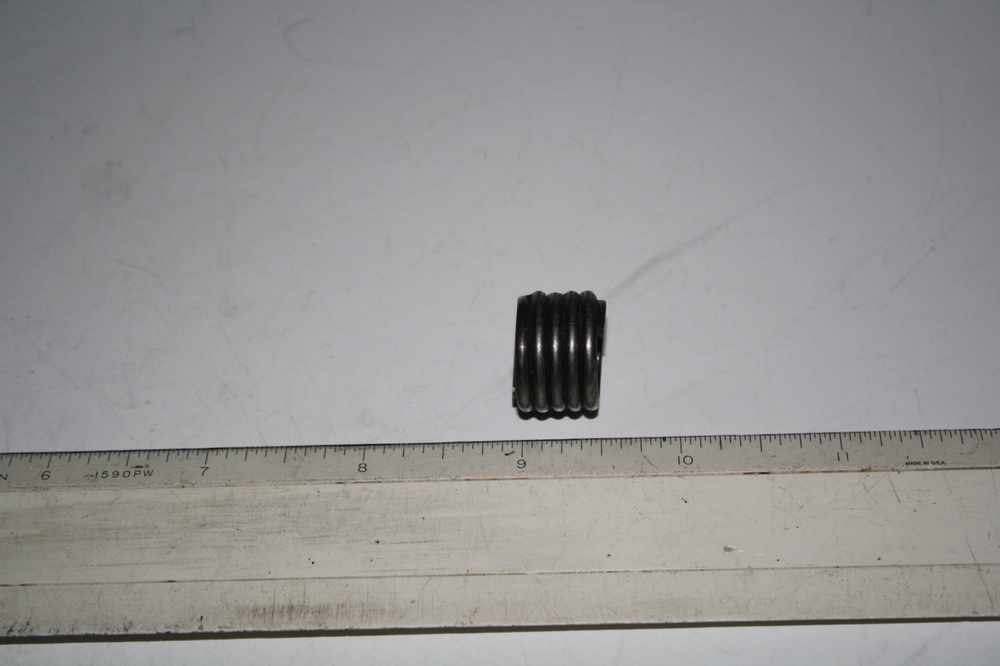
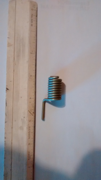
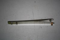
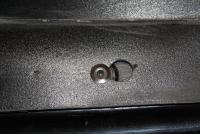
Thanks for all the replies. Zed Head: Definitely not a door spring. I have both of those in the car and they are both larger in diameter and quite a bit longer as well as spread open so they can be compressed. Captain Obvious: Yep, my rack looked just the same as yours and all the parts are back in it. The second spring came off the car all rusty, like most of the hardware. It's been sand blasted and replated with zinc and a chromate coating on top of the zinc. I used Caswell's CopyCad system and have done a ton of plating on the car. Mark Maras: The ends on spring 2 are both clean, no indication of any breakage. I looked at Heli-coils and they all seem to look like a spring that has been spread apart a bit. But a threaded insert is the best guess right now. I've attached a couple more pictures of spring 1 and one more of spring 2.

-
So I finally got my Z back on the road after a total rebuild but have a couple of springs that I can't figure out where they go. I have a feeling the smaller one goes with the steering rack, but I've looked through the FSMs and threads here and can't find any picture showing this spring. It's actually kind of baffling since I don't see how it can have any normal spring function since it can't be compressed or twisted. Perhaps it is used as a spacer?? Captain Obvious: do you recall anything like this during your rack rebuild? The second spring appears to be used in a twisting application, but I can't recall where it came from. I've taken about 400 pictures of my project, but sure wish I had taken a lot more during the tear down phase. Thanks.
-
I've been trying to remove the coolant line between the intake manifolds with no success. There are nuts on both sides but they won't loosen. I've used PBblaster many times and have used heat several times. Anybody managed to get these apart? Any chance they are reverse threaded? I'm also having trouble with the hose fitting that lines up with the coolant tube but is on the "outside" of the manifold. Thanks for any help.
-
So this really raises some questions about using replacement pistons, say for any engine that gets bored out. I see posts about using different rods with different pistons and nobody seems to think much about it. If it is a balance issue, then the new piston/rod combinations could be balanced and it seems like you would be good to go. If the combination of crank and pistons/rods needs to get balanced as an assembly, that would be a much bigger deal and I don't see any references to people having this done. So if someone replaces the stock pistons with forged pistons (which I assume are lighter), does that screw up the crank counterbalances, or is the crank balanced by itself and as long as the piston/rod assemblies are balanced, everything is ok? I hope I'm not sounding ornery , I'm just trying to figure out what can be safely done and what is a problem. The reason for all these questions is that one of the pistons I was planning to use (flat top) has a cracked skirt. I was going to try to get just one piston, and then balance that against the other piston/rod combinations. I'm finding this an interesting discussion.
-
So I'm working on an N42/N42 L28 rebuild. I've read several places you should always put pistons back in the same cylinder they came from. I can understand that you want to keep the complete rod together, but I can't figure out why you need to put the piston back in the same cylinder if you hone the cylinder and replace the rings. Any engine gurus out there who can explain if and why it is necessary to put the piston back in the same cylinder even when you have the cylinder honed and use new rings? Thanks.
-
So I'm swapping some flat top pistons from a 280ZX F54 block into my N42/N42 engine. I acquired them as part of a parts car I bought. Last night I discovered one of them has a cracked skirt so now I'm looking to get 1 or 2 more pistons. So anybody have some flat top L28 pistons around? Maybe somebody who has a stroker project? Thanks.
-
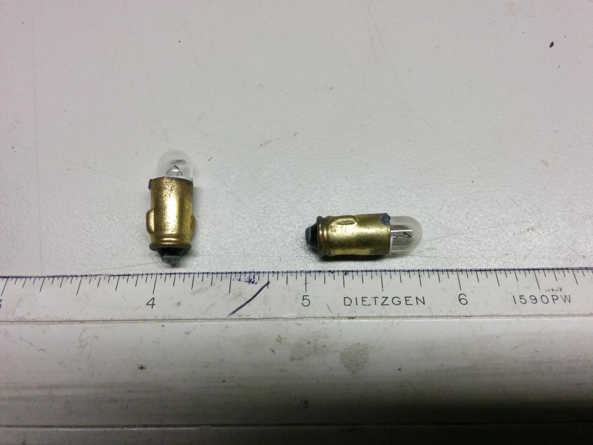
Thanks. It is also available as a regular bulb Eiko 16037 - 3898. I ordered the LEDs. I'll update when I get them.
-
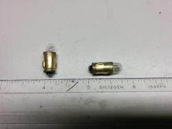
Here is a picture of two of the lights. The base is 0.268" in diameter.
-
Does anyone have a part number and source for the small light bulbs that are used in the console indicators for Choke, Fasten Seat Belt, and Rear Window Defrost switch. Mine just say 1.5 watts, 12 volts. Car is a '72. I've searched without any luck so far. Thanks.
-
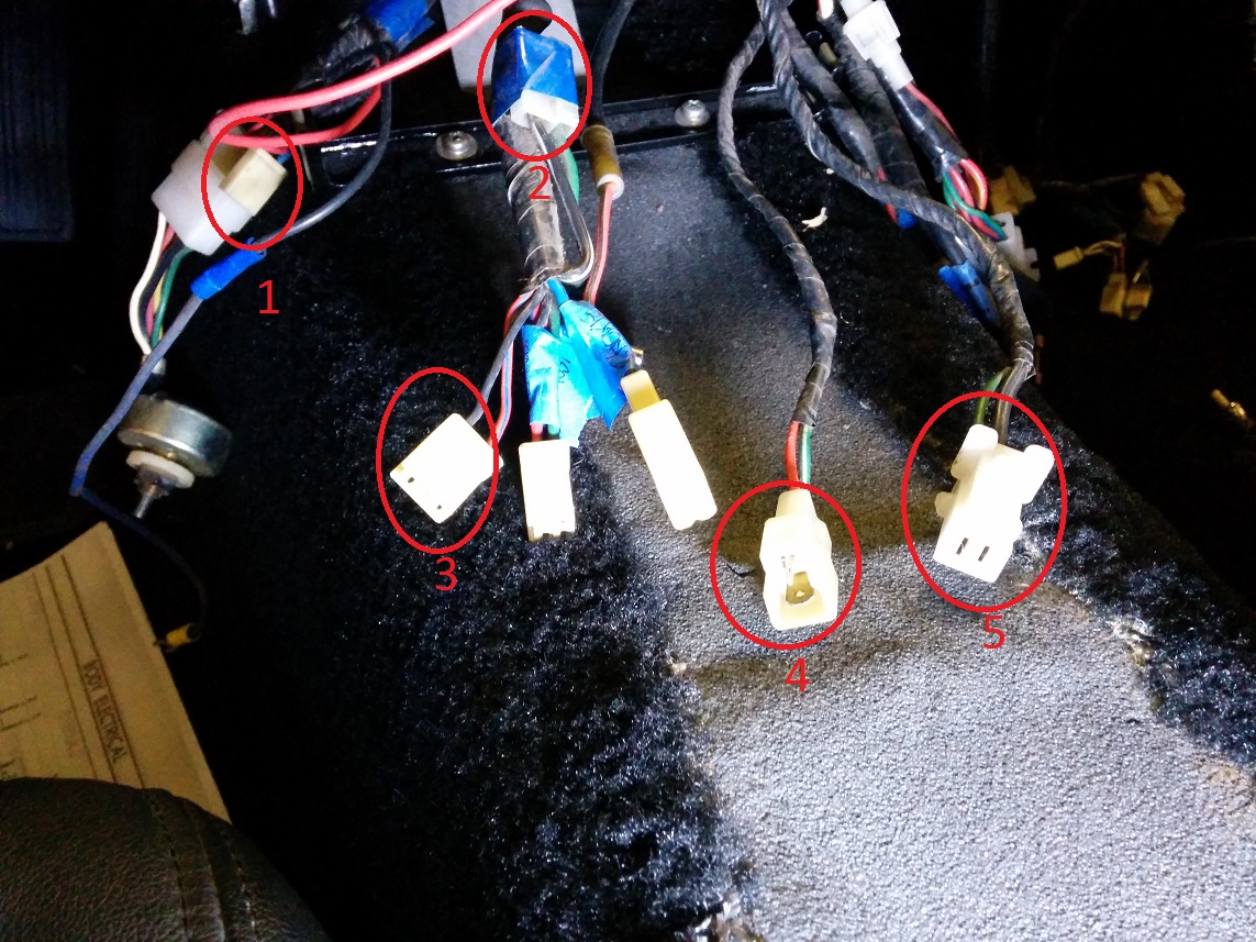
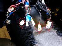
Car: 72 240Z; build date 5/72 This car was a real mess when I got it. I labeled all the existing connections when I took it apart and can get those back together just fine. Others that should have been there are not. For example, the Defrost switch/Fasten Seat Belts/Choke harness is missing from the little panel in the console. I have identified the two connectors that went to this panel. I still have 5 connectors in the center instrument panel harness that I can't identify and don't seem to agree with either a 72 or 73 FSM electrical diagram. Connector 1 is part of the heating harness. Two pin female with colors Red, Blue/White. Connector 2 is taped to the same bundle that contains the Defrost Switch/Fasten Seat Belts/Choke harness. I know that being taped to the harness like this means it was an option. I'm thinking fuel pump?? Two pin female T with colors Green, Black/White. Connector 3 is in the same bundle as 2. Two pin female with colors Black, Red/Blue. Connector 4 is standalone harness with a two pin male T connector. Colors are Red, Green/White. Connector 5 is standalone harness with a three pin female T connector. Colors are Green, Black, Black. Thanks for the help.
-
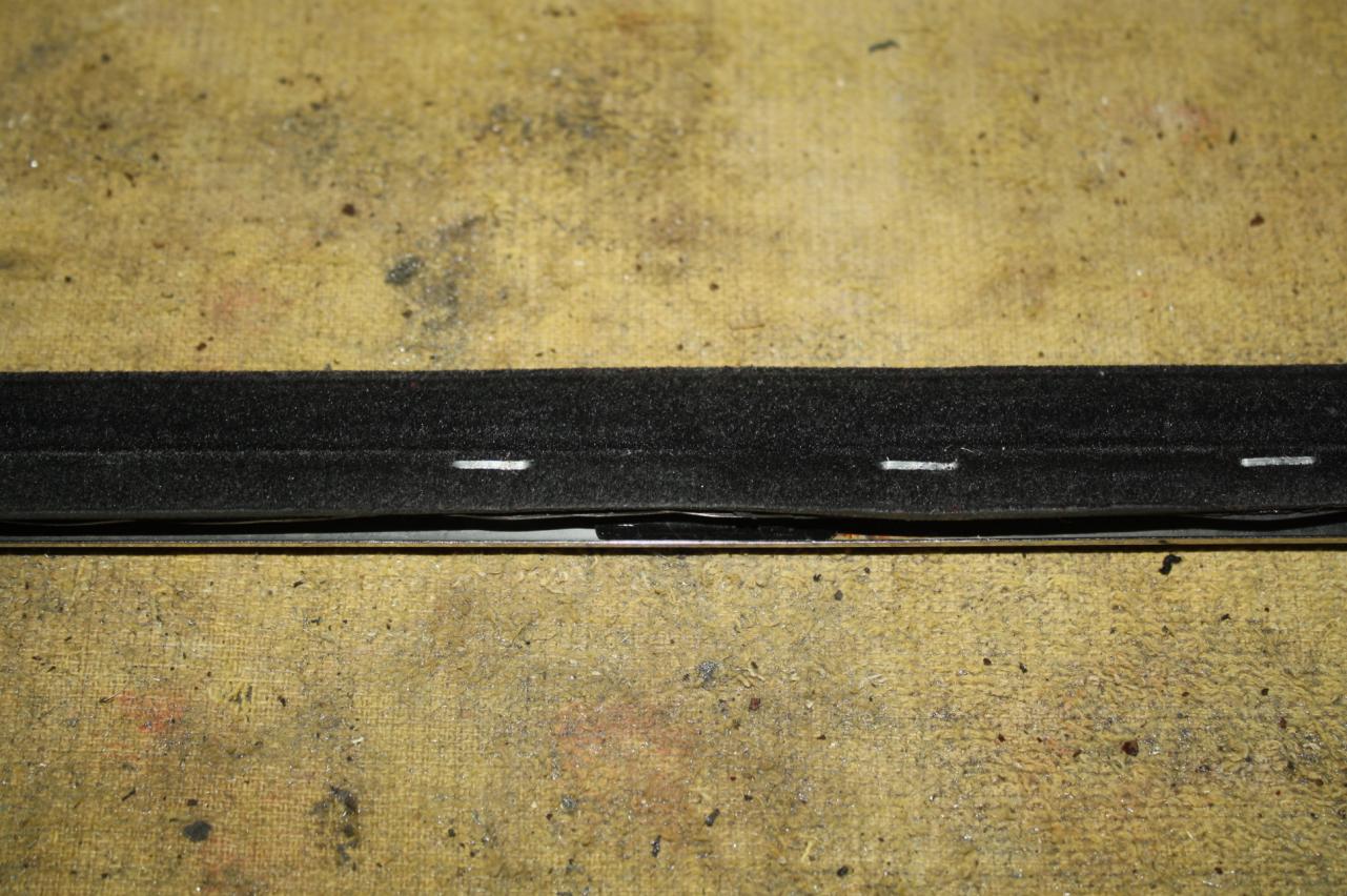
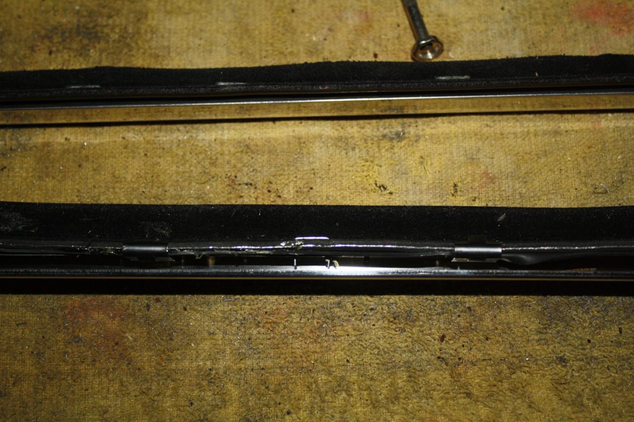
I just used the rubber to move the squeegee out. It didn't change the angle unless you are comparing it to the way Dave mounted his with the little lip over the top of the trim. I put the rubber in to move the squeegee closer to the window while keeping the natural angle of the new squeegee.
-
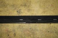
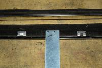
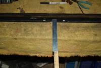
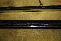
So I pretty much did what grantf suggested but went one step further. For the spacer I used a piece of old bicycle inner tube. I did use weather strip adhesive both to hold the inner tube to the squeegee and to act as a water seal between the squeegee and the trim piece. Finally, I decided I didn't think the supplied clips were going to keep it even enough, so I used staples. My steps: 1) I narrowed the side of the squeegee that mounts to the trim. I don't think you really need to do this, but it made using the clips a bit easier. 2) I used weather strip adhesive to glue the inner tube to the squeegee. 3) I used weather strip adhesive to try and seal the joint between the squeegee and the trim piece. 4) I used the supplied clips to hold the squeegee in place while I inserted the staples. 5) I made a little template/fixture with holes spaced to match my staple width. (staples were for a T50 stapler and are 3/8" long) 6) I used a backing piece of wood and carefully drilled the holes using my template. I was especially careful not to drill through the outside of the trim piece which would ruin your day! 7) I inserted the staples and used a needle nose pliers to both compress the inner tube/squeegee "sandwich" and start bending over the staple. 8) Repeated the process on both ends of the staple and then bent the legs flush against the trim piece. You can see the added rubber piece in the first picture as well as the template. The second picture shows the wood backing plate. Drill carefully! The third shows the staple before squeezing it. The fourth shows a couple of staples after squeezing them.
-
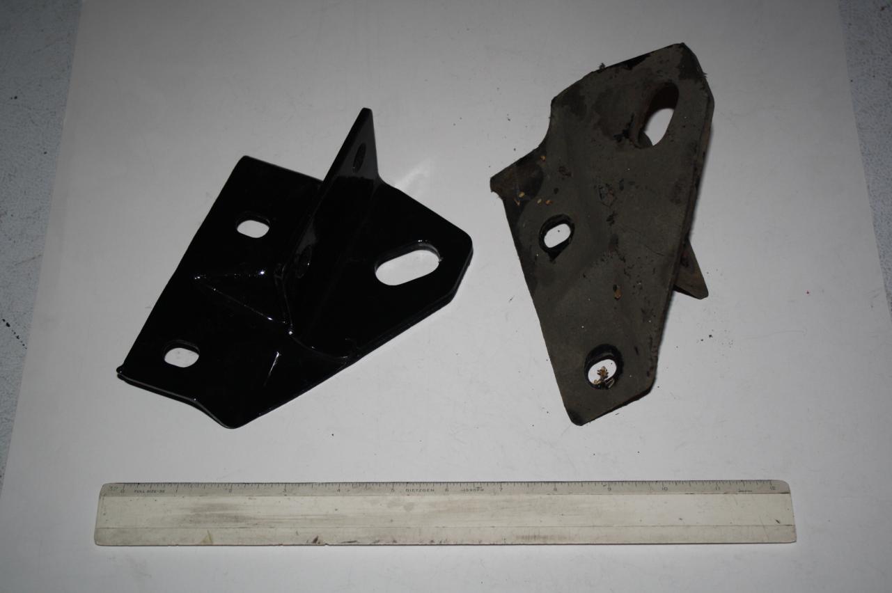
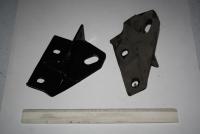
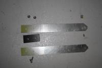
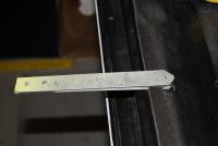
There is no indication that any part of the frame has been replaced. All the same (rusted) color and all the welding looks consistent with factory welds. I got a lot of extra parts from the PO and am starting to wonder if these brackets were ever on this car. If you look closely at the brackets, you can see they have mounting holes in two planes which appears different than any other tow hook I've seen, including the ones in Bonzi Lon's picture. I thought they might possibly be related to the bumpers since they are fairly heavy metal. I think I'll just set them aside for now. Just bugs me that I can't figure out what they are for!
-
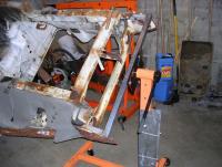
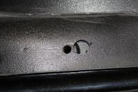
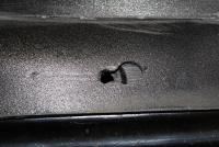
Interesting. Here is a picture of the front bottom before I had it sand blasted. It doesn't look like there is anyplace where the brackets were mounted judging by the paint and the lack of mounting holes. The car did have a plate with a tow hole mounted as you can see towards the bottom of this picture as well as a hook mounted where the ratchet is in this picture. Are there any other possibilities??
-
I thought I took a lot of pictures when I disassembled my '72 240Z four years ago, but I didn't take enough! Can you identify these brackets. That's a foot long ruler at the bottom of the picture. Pretty sure they are on the bottom of the car someplace. Thanks.
-
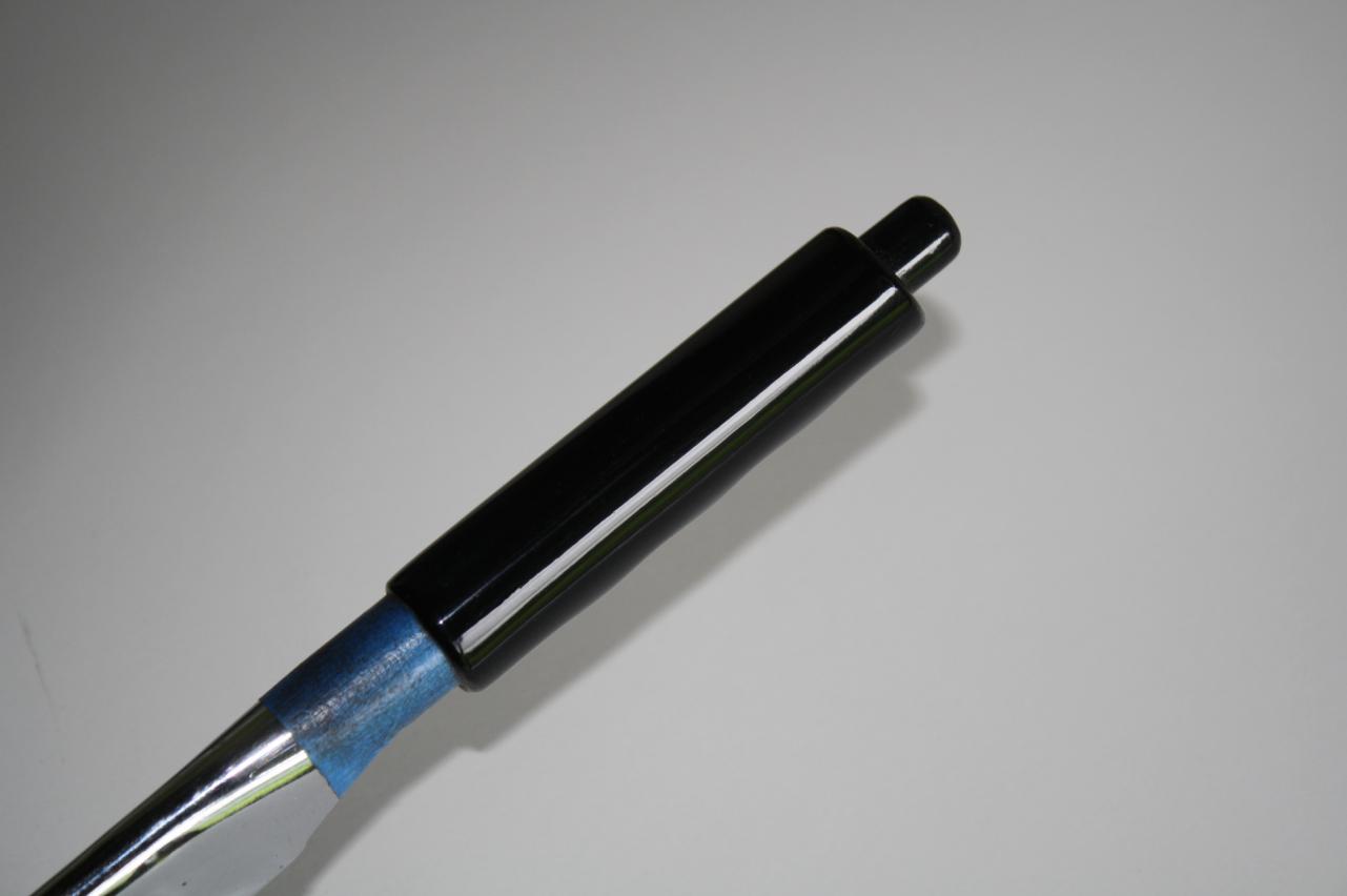
I used a 6" cotton polishing wheel (from Harbor Freight) on my bench grinder which turns at 3500 rpm. The polishing compound is the "Brown" compound also from Harbor Freight. I was a little worried about burning, but it didn't seem to be an issue at all. There was no paint involved, just sanding and polishing.
-
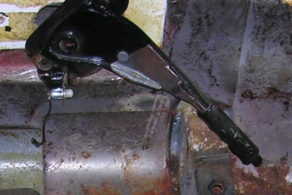
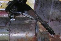
My '72 emergency brake handle was pretty beat up. I looked around a bit at buying a new one and then decided to try and fix my old one. The first picture is a severely cropped shot of the interior showing the brake handle before any work. The second picture shows the brake handle when I was done. The process was fairly simple: Sand out all the bad stuff with 100 grit, than 220. Then smooth it further using ScothBrite (burgandy grade grit) finally polishing it with my polish wheel on my bench grinder. It's hard to get a good picture of a shiny black object, but I'm pretty pleased with the result.

-
I am going through my 240z steering rack and am in the process of reassembling. I've measured and adjusted the "pinion rotation torque" and the "rack preload" but am having problems understanding the tie rod "swinging torque." The FSM gives the range as 5.8-10.8 ft lbs, but doesn't really explain what you are measuring. So for you suspension experts out there: Am I suppose to tighten the inner tie rod socket assembly so there is no movement until 5.8 ft lbs? If I do this, the tie rod is very difficult to move beyond the small center area. The "grease grooves" in the ball seem to prevent easy movement beyond the small central area. Does the ball move beyond this center area during use or is only the center area of interest? Thanks for the help.
-
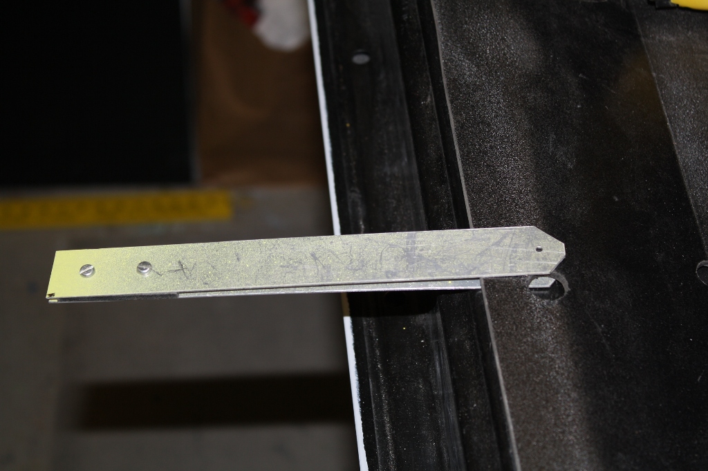
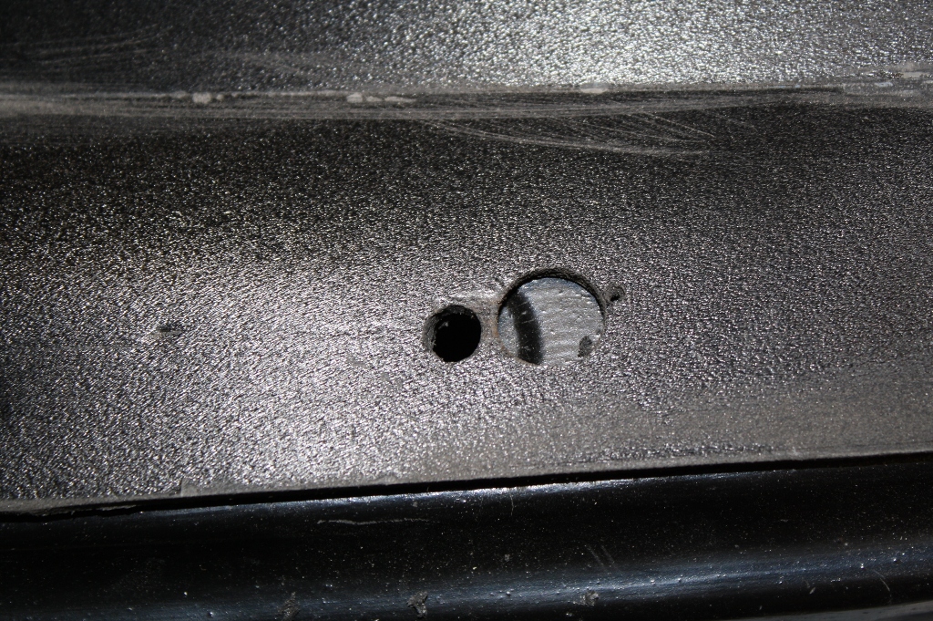
Don't know if you finished your trim clip installation, but I'm also installing new trim clips and thought these pictures might be of some help. I'm actually replacing my backer boards as well, so I have access to both sides of the trim piece. If you don't have access to both sides of the trim piece, you can use the tool shown in the pictures by making a cardboard or 1/8" plywood template of the trim piece, find and drill the holes as shown, then transferring that to your actual trim piece. Anyways, I built a "hole finder" similar to what we use to find holes when building our homebuilt airplanes. Some scrap aluminum, a piece of wood dowel that just fits in the hole in the car body, a piece of material the same thickness as the trim backer board and a little bit of hardware get combined as shown in the picture to make the "hole finder". Make sure the hole in the top piece matches the hole used to hold the wood dowel in place. To use, simply have the trim piece correctly positioned on the underlying body part, lift up the edge of the trim piece where you need to mount the clip, slide the wooden dowel into the hole, press the "hole finder" tight against the other side of the trim backer and drill your pilot hole. Take the trim piece off and drill the full size hole followed by trimming to the hole that allows the clip to pass through the trim piece. The pictures do a better job than the words. BTW, the plastic clips I used are from a '90/'91 Toyota Camry. They seem to have just the right amount of grip for the holes in my '72 240Z.
-
I would like to see some replacement boots for the hatch hinges. These are probably a bit more complex, but I've seen lots of interest over the years.
-
Maybe you are all old hands at this, but when I installed my Tabco doglegs, I tried real hard to match up the distances between the style lines on the old fenders and with the new doglegs. Lots of careful measurements, etc. What I should have done is had the fender installed on the car with the door in place as well, then match up the style lines between the fender and the door while adding the dogleg. As it was, I ended up cutting almost the whole fender width along the lower style line, repositioning the metal (read lots of hammering), then rewelding the gap. I think they came out all right, but it could have been a lot easier. Hard earned lessons from a newbie bodyworker.
-
Usually a weak ground will really hurt your starting performance. If the car turns over nicely, you probably have a good ground between the battery negative and the starter motor, which is usually grounded through the engine. If you don't have one, buy yourself a cheap voltmeter. Harbor Freight often has them on sale for $2. With the engine not running, but the ignition on, set the meter to 20V DC and measure the voltage between the two points the screwdriver touches. If you see ~12 volts, you have some "loose" electrons. Both points should be ground, so measure between the battery negative and both locations to see which one is "hot", likely the idle screw. Now try to find how the voltage is getting to the "hot" spot. Unhook any electrical connections one by one and repeat the test. If it is truly high voltage from your ignition system, it will only be there when the engine is running and would normally continue to be there as long as the screwdriver doesn't touch the idle screw, just is close, kind of like a sparkplug gap. Hope this helps.