


Jehannum
Free Member
-
Joined
-
Last visited
Everything posted by Jehannum
-
I don't have to worry about it anymore. My setup will work just fine with a jump now.
-
The guy who jumped me couldn't stick around, so I didn't really have that many options. I did learn something, though: that the kill switch can't be counted on to fail safe when you overload it
-
The "not right with this" was the fact that the battery was completely drained, so the alternator was running at capacity for a period of time sufficient to overload the switch.
-
Did you miss the SPST relay in front of the 1N5402? Because it's like 4x as big in the diagram. And I think it is relevant to location, because there aren't any kill switches with alternator included that will handle more than 20A. I looked.
-
I balked some years ago at the cost of replacing the stamped metal tray for my battery and instead put a container in for moving it to the hatch. In doing so, I became subject to a number of rules regarding how the car must be prepared to run on the track, the most onerous of which is a kill switch on "the rear-most part" of the car. For reference, here's the ever-popular internally regulated 60/70A Hitachi from a 280ZX: I've had a Moroso 74102 for some time acting as a kill switch (mounted to the rear panel, through the license plate), installed per the directions but I'm getting ready to run a 100A alternator (to support some other modifications), and realized that I'd been dangerously wrong on the install for some time. See, the 74102 is limited to 20A charging capacity, which runs afoul of even the most modest of 240Z alternators' peak output (I say peak, because certainly they aren't running at their rated output, when the battery is charged). I noticed this when I melted my first 74102 after getting a jump on a dead battery (the 10 gauge wire running back certainly got hot as well). So, after rethinking my options, I decided to go with the Longacre instructions (below) and use the switch to kill the field wire. This works fine, if you've got a race car, and you use the kill switch to shut the car down. Otherwise, it'll run the battery dead overnight. After rethinking my options again, I happened on a simple diagram that helped me out. Basically, the field wire should only receive ignition switched power. The problem, then, is figuring out how to get ignition switched power that won't also get fed by the alternator. So I kept the leg of the Moroso 74102 that their instructions intended for charging the battery, but used it as the source for a relay that is triggered by the ignition switch, like so (though adding the 1N5402 relay to keep the car from running on after the key is turned off): Now, you can run a (fused) wire from the alternator to the starter post at whatever you think is a safe gauge, which hopefully already has a big 2 gauge cable running to the back (either with its own breaker, or relying on the switch to melt-safe). I went with 4 gauge, and an inline 100A fuse (though not visible): I'll be switching to a GM 3-wire alternator soon, but this wiring should support the new one just fine.
-
I'm pretty sure that the + on the coil isn't receiving any voltage on key to "start" when cold. I'm going to troubleshoot that.
-
The new belt seems to have answered the mail. However, now it won't start when the car's warm, in the cold (<40°F). If the car's cold, it'll start regardless of the temperature. It'll start just fine from a roll, though. Think I'm going to pin my engine harness up, denude it, and see what I can safely strip out (+/hi/lo for RH headlight can pretty surely go away with my relay harness), what I need to replace, and what's buggered.
-
We'll see how it all goes. I replaced the belt, as the original was almost at the end of its adjustment range. By eyeball, everything looks OK to me.
-
I followed the rebuild guide from How To Modify Your Nissan/Datsun Engine book, which told me to not bother putting the oil slinger back in when rebuilding. I wasn't actually rebuilding (just replacing the crank damper after my last one delaminated), and then a couple nights ago, I threw my fan belt. Are these instances related? Is the elimination of that one shim just enough to screw up pulley alignment?
-
I'm happy to help people, but I doubt I'd sell anything. Thanks!
-
First try. I'm pretty pleased. In deference to the fact that I bought the amplifier off a Canadian, I had to play Rush as its first song. At any rate, the switch hands off control perfectly. When the radio's on, it plays AM, when the radio's off and the car's on, it plays over bluetooth.
-
An aluminum plate sandwich with 3.5mm standoffs to mate the amp's heat spreader to the sheet seemed pretty ideal, honestly.
-
And from the "inviting the stereotype" department, this is straight out of the service manual for the Hitachi radio.
-
I smoke tested the radio after the modification, and it puts the antenna up just fine, and makes AM radio noises when its on, so I didn't screw it up
-
Final packaging. I changed the scheme because I realized that the amp/bt combo would be on whenever the radio's off, including when the car's off, so I added a 4th relay to switch power to the whole shebang. Mounting location, after pulling all the wires through, and testfitting the amp itself. The antenna harness now carries the radio switched and ignition switched triggers to the back of the car. In doing so, I can now run a modern antenna without modification. Blue wire is the traditional blue wire - switched on when the radio's on. It's attached where the power switch attaches to the main board. There was a 4th hole for passing cable through on the radio, so I didn't even have to modify the case.
-
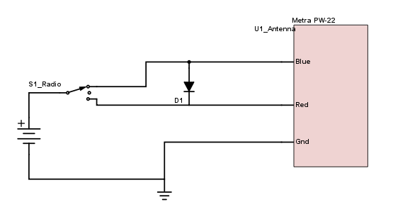
If you want a new-design antenna to work with the switch, you'll need to add a diode between the blue and red wires, then connect the hot-when-up wire to the blue wire, and hot-when-down wire to the red wire on the antenna. My schematic skills are rusty, but this shows what you'll need to do to make it work with the switch: both blue and red need power to go up, and only red needs power to go down. The way I accomplished that was to put a diode in between the blue and red leads. You'll need a fairly beefy diode to make this work. I just went to Radio Shack and found a big rectifier diode that was something like 400V@5A rating. Your mileage may vary, but I found that the L/R wire was hot when I pushed the switch "up", and the L/W wire was hot when I pushed the switch "down".
-
It's protected by the DPDT relay.
-
Could someone move this to the Z electrical section? I'm clearly a dumbass.
-
I took a deep breath before I touched soldering iron to the board, that's for sure. The radio itself is pretty well documented in the service manual, so I'm confident I could repair it, if need be. I just couldn't get where I needed to go without pulling the logic output (the switched +12V) out of the radio. On the bright side, there is a 4th hole in the bottom socket of the radio, so I didn't have to cut anything. I had one additional constraint laid on by the guy who built the amp - it can go into overheat protection if you turn it on without a load attached to both outputs, so I needed all 3 relays. One to power the amplifier (RY1, SPST), one to switch the speakers (DPDT, RY3), and one to trigger both at the right time (SPDT, RY2).
-
I'm about to wrap up what is (for me) a fairly exciting project on my 240Z, and I thought it would be nice to share, as it's not something I see discussed here very often. The goal: retain AM radio function in my Series 1.5 (5/71, so series 1 drivetrain and dash, but no hatch vents) 240z, while being able to pair with my phone and stream music over bluetooth. My materials: a class D one-board amp (bought from a guy who calls them "Shiznit", hence "U_Shiznit" in the wiring diagram), 50Wx2, a handful of relays, a line-level bluetooth board, two Match M5X speakers, and a spare speaker bracket from another 240z. My modifications: I created a switched output from the Hitachi TM-1081ZB by soldering an additional wire (I chose purple, to differentiate from the existing harness colors) to the switch side of the L10 choke coil (the Hitachi service manual is available online), and then running that out the bottom of the deck through the remaining open hole. The drawbacks: Limited to 5.25" speakers that fit in the stock hatch locations, I'm not going to win any sound quality or SPL competitions. I also had to crack open my AM unit to add the switched 12V, which can be nerve wracking. Honestly, my Z is pretty loud (2.5" exhaust, triple webers, rumbly cam), so the goal is really just to have intelligible audio in a stealthy package. Wiring diagram: Pre-relay testing configuration: So far, I've only mocked up the connections, but I'm running the wires soon (the entire thing should fit under the lid of the driver's side storage bin) for final installation.
-
No.
-
Unless you're running your compressor with an electric motor, you should be just fine with whatever alternator (even stock 45A units ran plenty of air conditioners back in the '70s). The only current draw above and beyond stock for those is the compressor clutch. And seriously, you're gonna drop an aftermarket aircon in, but you're worried about the originality of swapping a voltmeter in place of an ammeter? The voltmeter is a much more useful diagnostic tool to have. FWIW, after I swapped a ZX alternator into my Z, the ammeter constantly read slightly less than 0. This makes no sense in context, unless the battery wasn't charging, but it was, so I posit that there's something about the ZX alt swap that makes the ammeter readings suspect.
-
If it's internally regulated, it won't matter, because the ammeter won't read correctly anyway.
-
2) anything you do to the car affects the originality. I don't know about value (I'm not planning to sell mine). WRT aesthetics, there was only one model year cluster that had the same font for the voltmeter as the ammeter (the actual year escapes me at the moment, sorry). You can swap the gauge faces from your old fuel gauge onto the 280Z unit to keep the gauge face font correct for that one. 3) before modifying the circuit, you need to swap the guts of the 280 gauge into the housing of the 240 gauge - the mounting scheme is different. After that, splice the R/W and W wires together with an additional small 18ga pigtail, insulate the everloving crap out of the junction, connect the pigtail to the + terminal on the voltmeter, then connect the negative terminal to ground. Reassemble, you're done. 4) You shouldn't need to paint the face, if you swap the gauge from a 280Z.
-
Yeah, on mine the cause was that the coolant junction above the starter started leaking, and the hot wire (white) that ran from the old ammeter (which doesn't convey any useful information after switching to an internally regulated alternator) to the starter was shorting to ground through the coolant. That let all the magic smoke in the ammeter out in a hurry. I didn't bother with the delete plug, I cut everything back to the harness and ran it correctly to the alternator or looped it. Much cleaner, IMO.
