darom
Free Member
-
Joined
-
Last visited
Everything posted by darom
-
 Sarah, after I installed the rebuilt AFM with the stock CA lean settings, the best resistance setting I can get is to leave it alone at 0 to have my 17 in Hg. It is still a nice troubleshooting tool. Re: the idle and ignition timing - I am in the same boat: the car likes 850-900 rpms with the 14 degrees. 10 BTDC makes my car sluggish. Zed Head: you might be right about the idle enrichment. Now all of us need a vacuum gauge inside to observe it while at cruise. There was a reason why old cars used to have these gauges :-)
 -
I have also added the 5k potentiometer to the CTS circuit after chasing the lean condition of my 76 for months (it turned out to be a bad fuel pump). After experimenting with different resistance settings, it seems I can't add more vacuum to the existing 17 in Hg no matter how rich the mixture becomes. Actually adding more resistance makes the vacuum go down. The AFM is a fresh rebuilt unit to match CA EPA standards. I tried 10 BTDC, 850 rpm idle, then 14 BTDC (engine runs stronger at acceleration without pinging). Btw, Sarah, thanks for the CTS mod guidance :-)
-
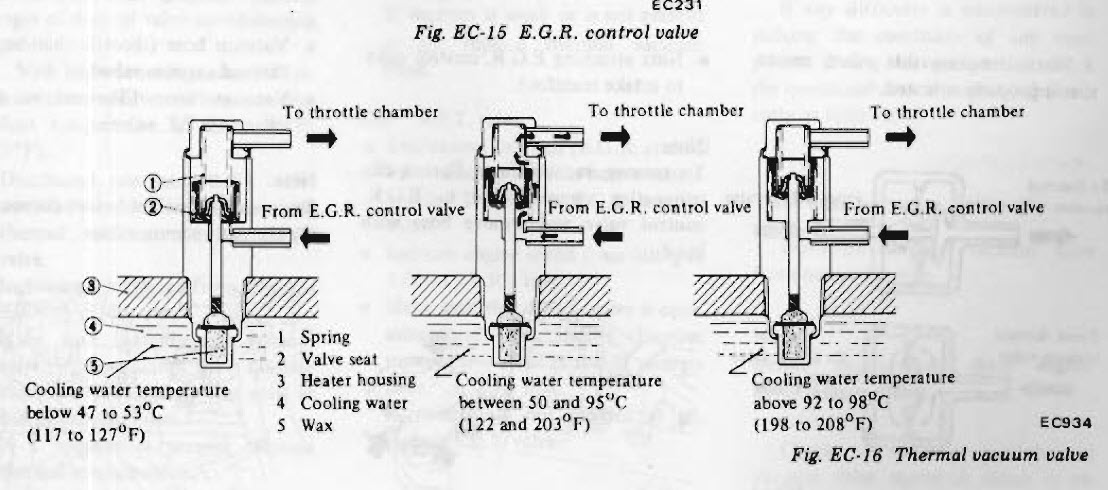
Hi FW! Thanks for checking my thread out. The tubing is indeed very small to allow for a nice water flow from the thermostat housing to the aluminum EGR thermal valve block and back to the lower radiator hose connection. I did want at some time to upgrade the pipes to a large diameter, but to me it was more work than re-routing vacuum lines :-) I didn't install any diodes when I did the 1979 alternator upgrade on my externally voltage regulated 76. I followed the atlaticz's instructions: http://www.atlanticz.ca/zclub/techtips/alternatorswap/index.html Do I need one? The car properly shuts off and the alternator does a good job charging the battery. I did re-do the brake light relay yellow wire (after the upgrade, the wire had the constant 12V with the key off and the relay was constantly energized). I connected a switched 12V to the brake relay from an unused antenna switch lead). The old 76 EGR electric solenoid was another drain - there was constant 12V present after the alternator upgrade. I didn't want to run another wire to the cabin's ignition switched lead through the relay to operate it. That's why I picked the later model ZX thermal EGR valve - it cleans up the electrical wiring nicely in the engine bay. I am not using the 1978 back pressure exhaust gas transducer since my intake/EGR exhaust doesn't have a port to connect to. Thanks! PS. After talking to my hotrod buddie, he thinks that EGR valve's threads are NPT! The threads are very close to the 1.5 metric. Or British NPT?
-
I took the plug out - it measured OD 17mm with the 1.5 thread pitch. Does M16 x 1.5 sound right? The thermostat's housing radiator hose pipe's OD is 36 mm, ID 30mm. Will a 32mm adapter be a nice tight fit? Thanks!
-
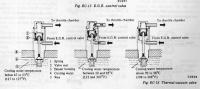
Hi guys, I converted my electrically operated EGR switch solenoid on my 76 to the 78 EGR control valve (1978 FSM, EC-11) which is temperature operated. This allowed me to get rid of the potential battery drain condition in the future (after my alternator had been upgraded to the internal voltage unit, the solenoid was constantly energized). The 78 EGR control valve is installed in the aluminum block which is located under the air regulator. The problem is the temperature in that block doesn't get more than 52-55C. I tested it with my laser thermometer. The valve doesn't open, thus it doesn't allow the vacuum to operate my EGR valve. I tested the valve in the pot, and it opens at around 65C. I would like to install the adapter in the top radiator hose and screw that EGR control valve there, then block off the thermostat housing hole for this block and get rid of the snake coolant line going to the RH side. The top radiator hose temperature would be the best source to operate that valve. What is the thread size of the 78 EGR control valve? Is the top radiator hose size 1 1/4" or 1 3/8"? Rockauto comes up with both sizes. Thank you!
-
UPDATE: I finally replaced the PO's fuel pump (it is one of the Autozone replacement pumps, Airtex). This fixed the lean condition finally! What confused me was the fact that the old pump was delivering the "prescribed" by FSM fuel pressure with the key in ON (starter solenoid disabled) position and at idle with the stock FPR. Since I couldn't verify the fuel pressure while driving, it was my last stop.
-
Resurrecting the old thread. I just fixed my 5th gear by following Sledz's advice. The shifter wouldn't completely engage the gear - thus making the shifter pop back into neutral. Thanks Sledz!!!
-
It is not difficult - having another set of hands will help. 1. Lift the rear of the car up 2. Drain the gas 3. Remove the passenger side wheel, remove the plate that covers the filler hose, loosen up the hose clamps 4. Using another jack with a long 2x4 wrapped into something soft (to avoid scratches on your tank), support your tank. 5. Remove the 2 tank support straps 6. Start lowering the tank with your jack. Once it clears the bumper, you will see some emissions hoses on top. Disconnect these. 7. While you are lowering the tank, disconnect the filler hose (probably one of the biggest pains in the neck). 8. You are done - 50% at least. A few good things to do while "you are it" - Inspect the top emissions hoses and replace them if needed - Inspect the filler hose, if it is old, hard and cracked (as you already know it) - replace it. - Remove the fuel sender inside of the tank, with multimeter check the potentiometer's readings, clean the dial. Replace the O-ring. - Inspect the pick up fuel tube inside and check for any cracks. - Inspect the sender's electrical wiring, clean the contact leads. - Repaint the tank straps, if rubber strips are gone, replace these. - Take the tank to a radiator shop and let them clean it and vacuum test it for any leaks. Putting it back is more time consuming - a helper will be a nice addition at this point. For me it is always the filler neck struggle due to tight space. Regards!
-
Update: took the car to my mechanic and did the CO test at idle (he doesn't have a dynamometer). The AFM was adjusted too rich. Opened the AFM case, the previous technician (Ed, from 11/2002) didn't even installed the return back/bumper spring. After 12 clicks CW, the CO went down to under 1%. Took it back to the smog place, the car failed the smog again with almost the same numbers, 15 mph - 5%, 25mph - 6%. At this point I just told him to charge me the $95 'diagnostic fee' and tweak my AFM. After going back and forth, he finally made it pass, but pretty close to failing under 25mps. Besides the set screw in AFM, he opened up more the idle bypass screw. 15 mph - CO 0.00 (max 1.36), HC 6 (max 214), NO 221 (max 1364) 25 mph - CO 0.98 (max 1.16), HC 10 (max 181), NO 28 (max 1224) The discrepancy between the 15 and 25 mph testing tells me the AFM is about to give up a ghost. What do you guys think? During all this my "Floor Temp" light went on and the water temp gauge was getting very close to the red zone. Should I bump my ignition timing from 10 BTDC to 14-16? While pulling out of the smog shop, my car died from a very low idle speed. I had to unscrew the idle screw to get back home. I revved the engine at idle and it made a popping noise (too lean?) I feel like adjusting the AFM myself again and make it run a little on a rich side. I will start looking for a rebuilt AFM (it did pass all the Fuel Inj. Bible tests, and the FSM tests with applying voltage and reading the volt settings at the pins). Thanks!
-
I found some printed numbers on my catalytic converter and it appears to be CA legal: 94000 0607 CA/CE 99000 It looks clean with an anodized 'cooked' finish.
-
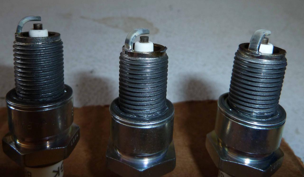
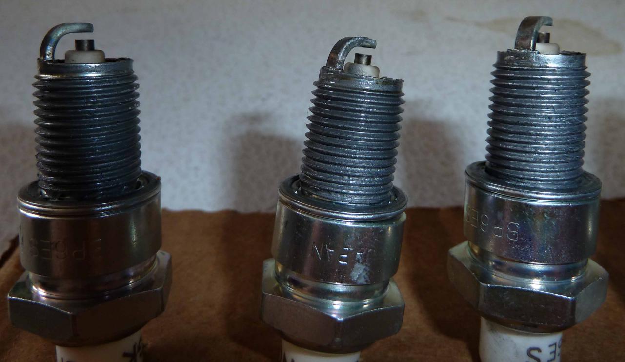
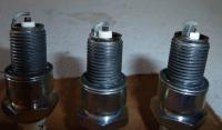
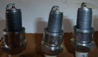
That was my suspicion about the middle/lean TPS position. The cat was installed by PO 2 years ago - he had to install it to pass smog. I can't tell its condition without removing. It looks like an aftermarket unit (no brand name or CARB numbers). Btw, thanks for reading my essay :-) I just did the CSV check with voltmeter connected. It is warm here (about 75F) and it never got activated. I restarted the car a few times to double check. CSV is not running. The fuel pressure starts at 30 psi, when warmed up it drops to 28psi (it also might be due to the cheap fluid filled gauge not taking the heat). The only thing that doesn't work at the moment is the air regulator (or auxiliary air valve). It stays open all the time. I ordered a new one from Nissan. I have 2 junk yards CSVs and none of them worked for me. After adjusting the TPS/throttle spring the spark plugs look ok, dry and on a lean side. Spark plugs order: Left picture: 6-5-4 Right: 3-2-1
-
Greetings, Before I bore you guys with a lengthy post, here is the question: can a misadjusted TPS (in an always lean condition) cause high COs? My numbers were at 15 mph - 5.01 (allowed 1.36), and at 25 mph - 5.42. HC - 113 (max 214) at 15 mph and 86 (max 181) at 25 mph. The car is 1976 280z, stock + catalytic converter. My TPS and lousy weak spring linkage wouldn't return the idle back to the far right/middle TPS metal contacts and would stay in the middle position (lean/cruise mode). The dashpot also would be very slow to return the idle. I searched and found a bunch of threads where TPS was one of the reasons why our cars might run rich. My dilemma is that in their cases the TPS was in the WOT position, which commands ECU to dump more fuel, thus creating the rich condition. In my case it seems that the TPS was always in the middle/lean position. Would this attribute to my smog problem with high COs? Logically, it should be running lean. Am I wrong? Here is what has been done: - FI Bible and fuel injector FSM - all troubleshooting steps returned positive results (thermotime switch, water temp sensor, operation of the CSV, AFM resistance, AFM temp sensor readings, injector operation). The sensor readings were taken with cold/hot engine. - all vacuum hoses and PCV valve are new - AFM rubber boot is new - new intake gasket - fresh oil change, oil filter, air filter, new NGK spark plugs (gapped at 0.039) - fuel tank was cleaned, fresh gas and fuel filter. The car idles at 800, ign. timing is at 10, vacuum is at 17, fuel pressure (not running test - 36 psi), running it stays at 30 psi. The CSV is not leaking. The spark plugs look dark, cylinder 5 - shows some oil/fuel (hard to tell). I haven't played with AFM yet. This is going to be my last stop (hopefully). Air regulator is faulty (it doesn't close) and i just pinched the hose. It will be replaced. The car starts with a half-turn of the ignition key. It runs great. It passed smog 2 years ago. What I haven't done: - pull the fuel rail with injectors and check for leakage (especially, cylinder number 5) - attach voltmeter to the CSV while the car is running and check for voltage presence (to isolate CSV dripping during the normal operation). I have also adjusted the TPS to have proper contact engagement at idle. The contacts break loose as soon as the throttle is applied (how important is 1400 rpms?). It was really hard to aim for 1400 rpms limit to disengage the contacts. The WOT is applied almost at the end of the throttle pedal application. I installed 2 springs to the throttle linkage. It closes and returns to idle fast. The dashpot was adjusted to catch the throttle movement at the end. My mechanic's smog equipment is getting repaired. I will take my car next week to do a simple tail pipe sniffer test to see how rich the mixture will get. Before I see him, I'd like to cover all my bases. We probably can tinker with the AFM at his shop. Thanks in advance for your input. Den
-
You can tell the difference by looking at the seat rails: 240 seats have straight mounting rails. 280z - the rail ends are angled. The rails are easy to remove and interchange between the 240 and 280 seats. I am not sure about 260 seats. Maybe someone else can add? I have 76 seats that were trashed. 240 seats fit like a glove with the rails replacement. The shape wise the seats look identical. The only difference I noticed was the reclining handle. The 280z reclining mechanism plastic cover didn't fit the 240.
-
Blue, excellent idea - I can fab a nice looking aluminum piece and screw it down to the tranny tunnel hump to push the carpet away. Thanks!
-
Agreed, the only problem is my carpet is tucked under the central console (which was a royal pain in the neck to install). The console retaining bracket holds each side of the carpet :-(
-
Sorry, I should have mentioned it in the post: the car has a standard 5-speed.
-
Hi guys, I think I overdid with my sound deadening material, jute padding and a carpet in the gas pedal area. My 10 size shoe rubs against the brake pedal. The interior has been redone, the carpet/jute padding were glued there since the molded carpet was 'sticking out' too much causing interference with the gas pedal getting stuck on its own. I was afraid I was going to repeat the stuck Toyota's gas pedal syndrome :-). I found a thread which deals with replacing the pedals with aftermarket parts: http://www.classiczcars.com/forums/showthread.php?15438-Pedal-Upgrade&highlight=gas+pedal+move I am considering a few options: 1. With a BFH and 2x4, hammer down the tunnel metal. 2. Buy the replacement pedal covers hoping their size will be smaller than stock (wishful thinking?) 3. Relocate the brake pedal to the left, if possible? The brake pedal's rod is quite thick, it will be probably hard to bend it. In your opinion, which one is better or if you have your ideas I'd appreciate it. Thanks in advance.
-
EverRude, before you installed the hazard switch, take it apart (4 small screws) and clean the contacts inside with a fine grit sand paper. It will take you a few minutes.
-
Eric, If you could find out and post here how much your best friend is going to charge us for ceramically coating the stock exhaust manifolds, I'd appreciate it. There must be a reason why Nissan put that heat shield there :-) Thanks!
-
I used one of the Jegs' battery terminal covers on my positive post: http://www.jegs.com/i/Taylor/895/20670/10002/-1 or this: http://www.amazon.com/Ancor-260392-Electrical-Terminal-Rotationg/dp/B000NI1FVC
-
Chris, Good job. Your whole setup is begging now for a carpet or vinyl cover or better yet, a fiber glassed top! :-)
-
Pops, do you have just rear speakers, and nothing in the front? I am debating between having just 6x9 in the rear, or fabbing 5 1/4" speaker enclosures and installing them in the kick panels (little room there unfortunately). Thanks.
-
Prefer local pick-up in Bakersfield, CA. From 76 280z: - removed used a/c parts (compressor, seized pulley, vacuum canister, brackets, some relays and vac. tubing). The box is heavy and needs to go as one unit, please. A/c was disconnected in the car when I bought it, the a/c compressor's condition is unknown. A heater core will be included. Chevy 350 engine bare block, 4-main, I acid dipped it a few years ago, still has surface rust. 0-over if I am not mistaken. It will definitely need to be bored out. For faster response please email me at simzealot at gmail doooootttttt com. Den
-
Hopefully, final update: - the replacement ECU got my car running again without any hot wiring gimmicks to the CSV. Thanks to all who helped me through this ordeal!
-
Adrian, 1. I mistyped - sorry, it was measured 2.68 kOhm 2. Re: options pin 1 kick-back - I will have to take the ECU's cover off to get my multimeter to the pin number 1 to get that voltage. I believe it does go to 400-600V range. 3. Output stage transistor on the side - easy to replace since the solder points are big with plenty of space on the circuit board. There are actually two of them. 4. I will trace pin 1 lead and see where it connects to on the board. I can borrow an oscilloscope from a friend of mine. I am not sure if my voltmeter has hFe setting. I will double check it. I'd love to fix my bad ECU even if I bought/have another unit. I don't mind working with electrical problems because there is logic to them (broken inside distributors or leaking oil pan is a different story). We can keep the resoldering ECU business off this board via private emails to keep other threads on top. If classiczcars members are interested, I can attach the PDFs/images of troubleshooting later to this thread to sum it all up. Thank you!