xs10shl
Free Member
-
Joined
Everything posted by xs10shl
-
Just my own opinion here on Eibach - I've recently installed 2 sets of Eibach springs on 2 cars- one new set and one used set - and to my eye, the nose of both cars still sits too high relative to the rear ride height. I've heard that this happens to some folks and not to others. Upon examining the coils under load, the top 3 turns are fully compressed against each other, so it's probably a simple matter of cutting off a full coil turn to lower the car an additional 1/2" (the width of the coil itself), which would be a noticeable stance improvement. I'd venture to say that this shortening would likely yield minimal degradation of ride quality, given the full compression of the to 2-3 spring turns while under load already.
-
Yes, this is perfect!. Many thanks! I'll use this to give the fab guys something to go by.
-
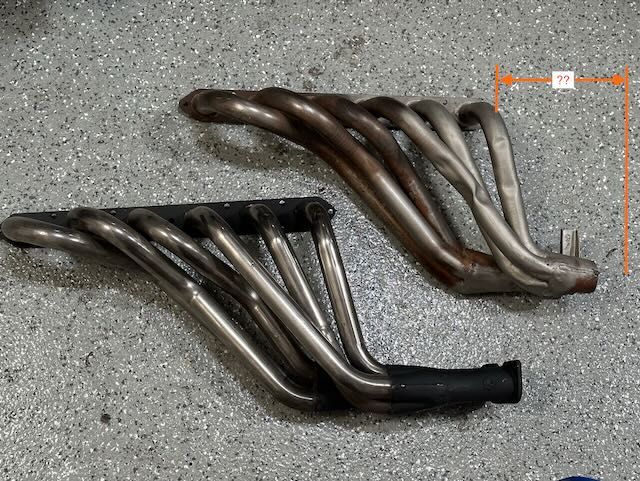
Today's puzzle. I have two s20 exhaust manifolds, which to my eye appear to be meant for the C10 GTR models. One of them has been shortened, i'm guessing for use in a Z432. Since I don't have an original-looking Z432 S20 exhaust manifold on my Z432, I thought it would be a suitable exercise to get this manifold re-flanged for use in a Z432. At the same time, I'd replace the one section of pipe that has somehow been squashed. Not entirely sure of the origin of these manifolds. Any thoughts as to where they might have come from? The pipes appear to be stainless. The cut unit appears to have a custom mounting bracket, which I'm guessing by it's position was mounted onto a custom bracket off of the bell housing/rear of engine block. The bracket does not appear to be aligned with anything I can see on my cars. What I'd like to know is the horizontal distance between the last bolt-hole on the exhaust port and the exhaust pipe flange. In other words, how far back from the rear-most bolt hole is the flange located, in order to properly bolt up to a standard exhaust setup? If anyone has a part that's out of the car (even an aftermarket bolt-up part will hopefully have the same dimension) this would be a straightforward exercise, and I'd be grateful.
-
Great info, @HS30-H. Entirely plausible these units contained the same internals, even if the exterior differed slightly. All the mods I can see make sense. Moving the power-transistors aids in cooling, and for assembly. Part of me wants to think that the possible market for the intercom was also small plane use, but the caveat is that most plane intercoms that I've seen use a 2-plug system - one for mic, and one for speakers. Just looking at the evolution of these models is interesting: The original systems had too much stress on the jacks, so they added extensions and jack boxes. Then the wires of the boxes got stressed from dangling, so they added cables as stress-relief for the wires - that all feels a bit like the evolution of a custom modification, rather than from Teikoku Dempa. It would be something to find this box in another application, which would answer some questions.
-
Thanks for the tip @240dkw - looks like a great selection of old-school electronic parts.
-
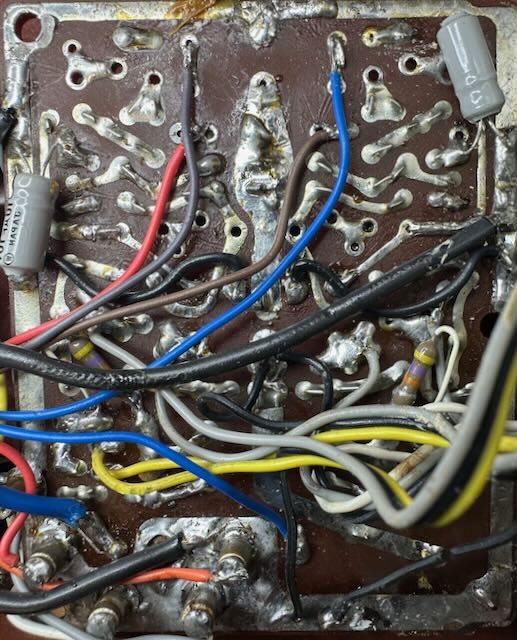
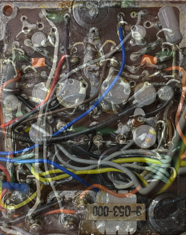
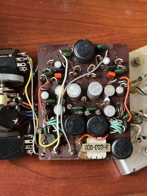
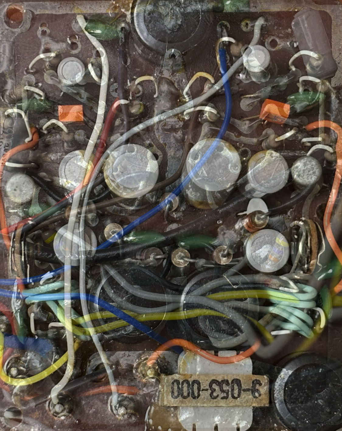
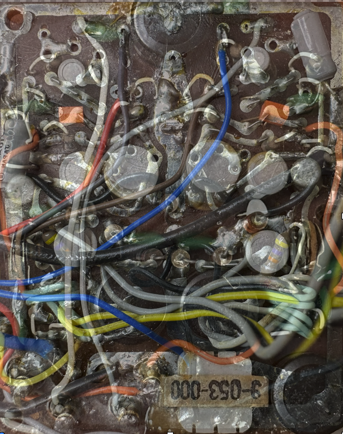
Keep it coming @Captain Obvious! FYI there was some shielding between the transistors and the other components which I removed. I'll have to remember to re-insulate. I've attached a few more photos, should you be bored this afternoon at work: PCB front and back. The back has been mirrored in order to make is possible to overlay one photo with the other, and make it easier to trace the circuit. I'm using a simple paint program to adjust opacity - it's much easier than handling the board, and breaking wires off! The top part of the circuit looks pretty straightforward, and not too dissimilar from your schematic. The bottom is a bit messy, with all the extra jumper wires in the way. There's an odd resistor in-line on the central power feed, separating the top and bottom circuits, and you are right that there are 2 large capacitors also hanging off this power feed (one on each side of the resistor).
.jpeg.17b3b494ea7d5ce6d929dbccb73397fc.jpeg)

-
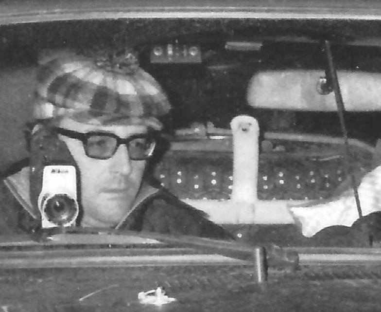
Thanks @HS30-H for the period photos - I especially love the driver's expressions that were captured, even if perhaps only by happenstance. Fall looks almost amused at the state-of-the-art rally equipment, as if he feels as if he's been promoted to "flying-ace aviator". Aaltonen, in contrast, has a "Yeah... nah.." look of mild skepticism with the whole exercise.
-
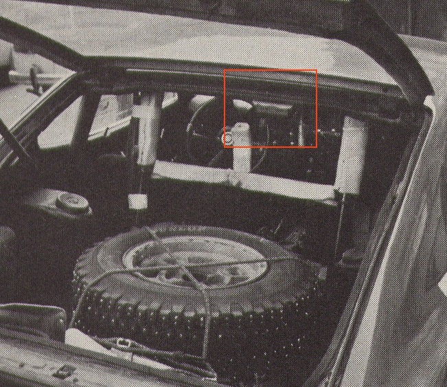
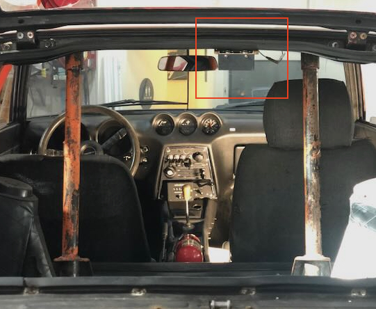
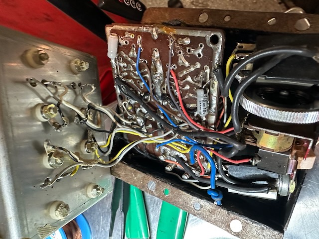
For the 1971 Monte Carlo, the Works team appeared to employ (from what information I can gather) what is basically a 2-channel power amp with gain control to facilitate communication between driver and navigator. The essentially muffler-less cars were already loud to begin with (by all accounts), and subtracting any sound deadening, plus the incessant constant rattling of two in-cabin fuel pumps, one could imagine the occupants would be losing their voices around day 2. Interestingly, I have a fair number of period photos where the team did not appear to be wearing headsets while underway, so perhaps the system didn't provide the expected benefit, apart from when the occupants donned helmets. I believe mine to be original hardware, as I have a detailed picture of it installed in the car from the 71 Monte Carlo (last picture below), and another from October 1971. It is a very compact 12V device, made by Teikoku Dempa Co. LTD, using 1/4" headphone jacks to a pair of mono headsets with microphones. Teikoku Dempa has been in business since the 1940s, making radios under the Clarion brand name. It's not clear to me whether this device was stock, a special order by the Works team, or potentially even a modified over-the-counter item. The unit wasn't working, so I decided to take it apart for a little exploration and diagnosis. It didn't take long to discover a fair number of leaky capacitors, which are in need of replacement. Probably best to replace all that I can find components for. Although Ive taken a circuits class in my youth, I'm not an electronics repairman, so I'm on the hunt for an enterprising repair shop, likely a tinkerer with an oscilloscope who would want to spend a few hours reverse engineering the board, replacing the caps, and matching the system to my headsets. I'm taking a first-pass stab at creating a circuit diagram using some simple circuit design tools, so whomever takes on the job isn't starting from scratch. Worst case scenario is that I'm forced to put the original electronics aside for storage, and retrofit the box with a modern 2-channel amp, so it at least looks the same. In the mean time, it would be fun to find out where the Clarion on/off switch and volume knob came from. Perhaps there is an old Clarion transistor radio which uses the same equipment?

-
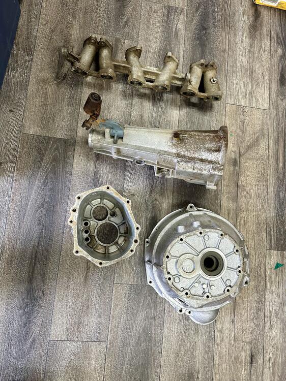
Those 4 pieces were $150 total. I thought the price was so good that I brought a second set for the same treatment. This new set is dirtier, so it may cost a little more to de-grease.
-
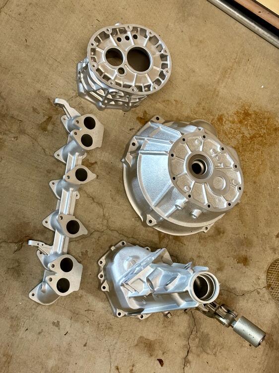
I've got a small vapor honing booth at my shop, which is good enough to clean things like windshield wiper arms and carburetor lids. For the big stuff, I tried out a new local service called Spray Technology in Santa Clara CA, who had heavy-duty equipment, and I was not disappointed. Everything looks better-than-new.
-
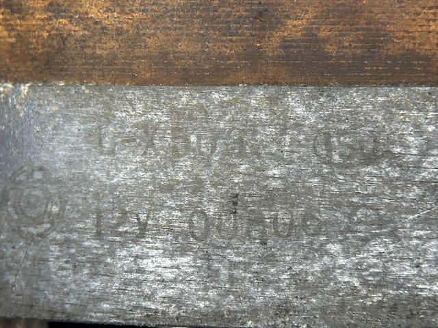
Thank you @HS30-H - I used your pictures to locate some incredibly faint imprints of the Alternator: L-X503 12V 00806. I'm supposing the difference in the last number indicates that these are a run of numbered units?
-
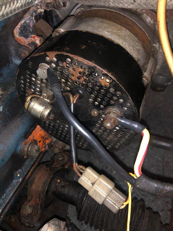
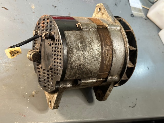
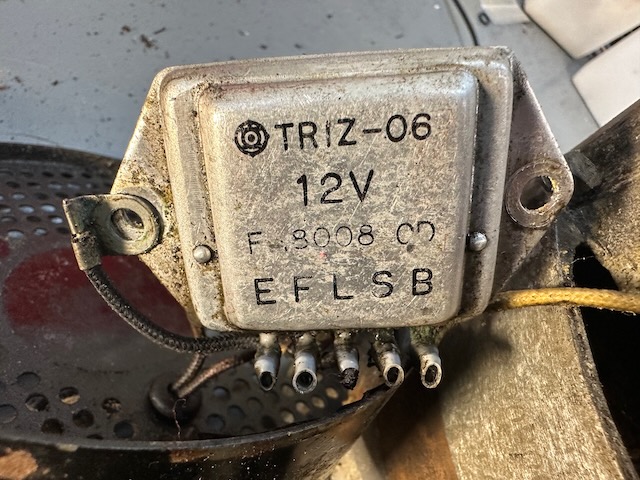
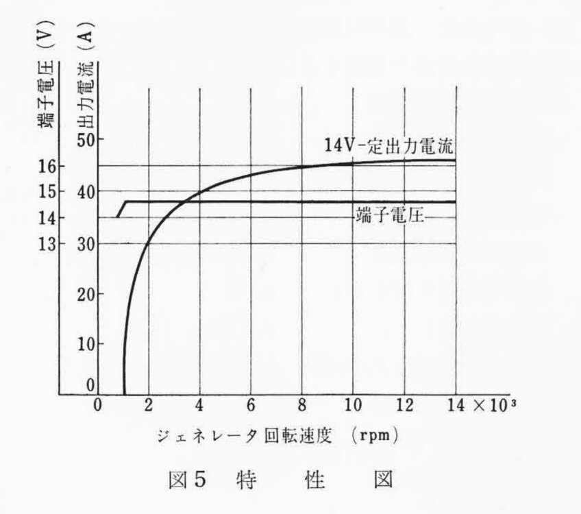
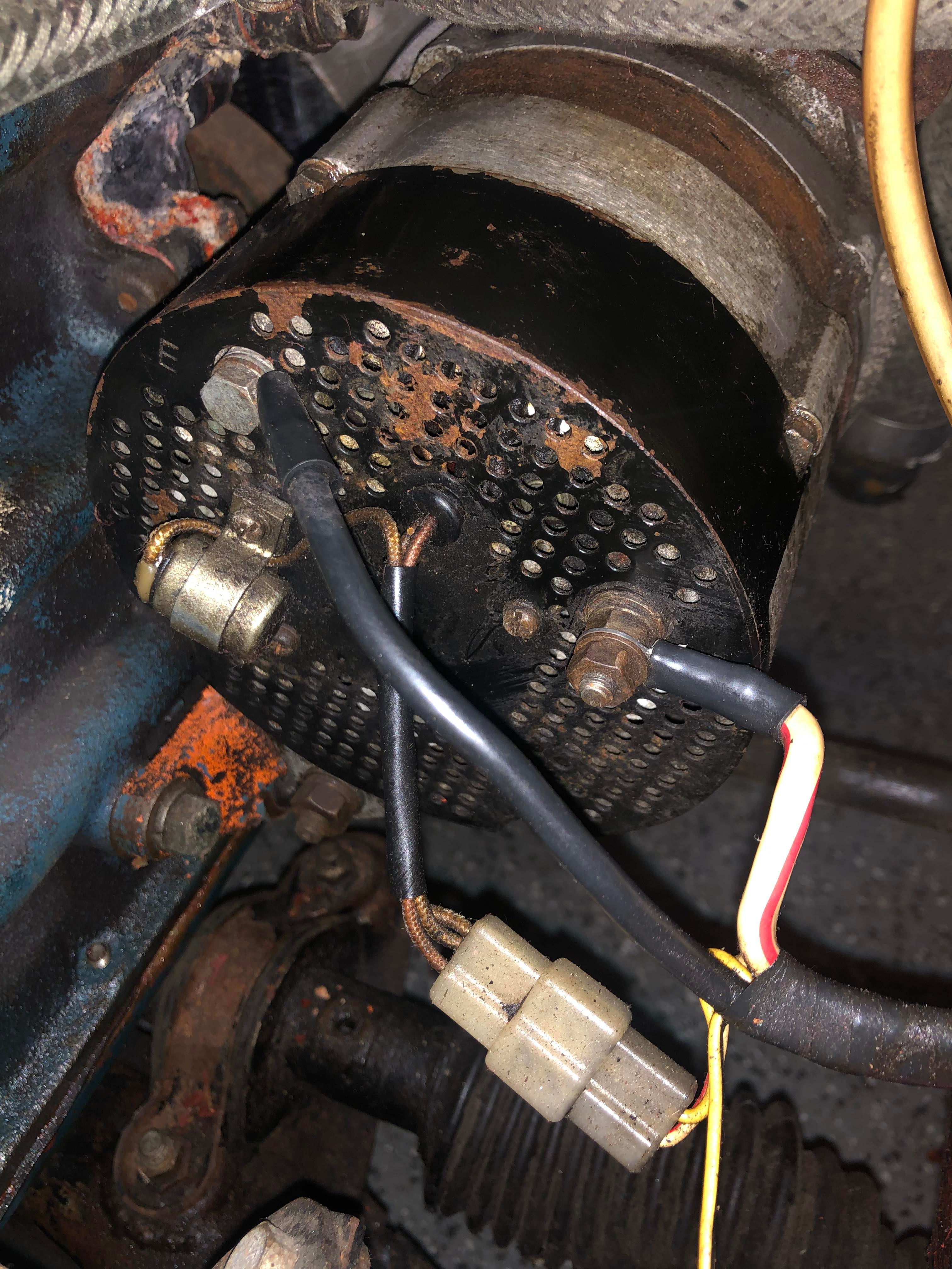
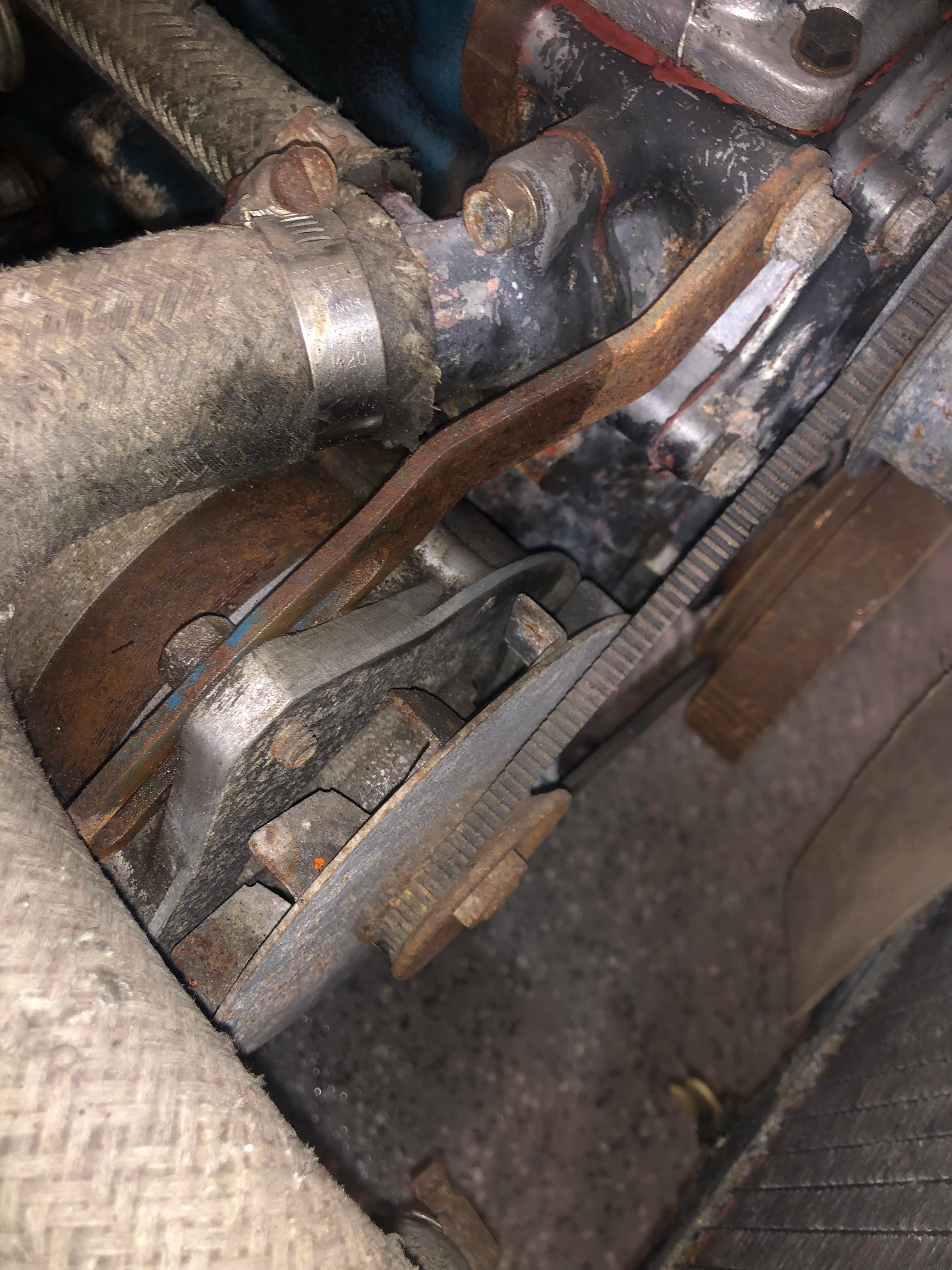
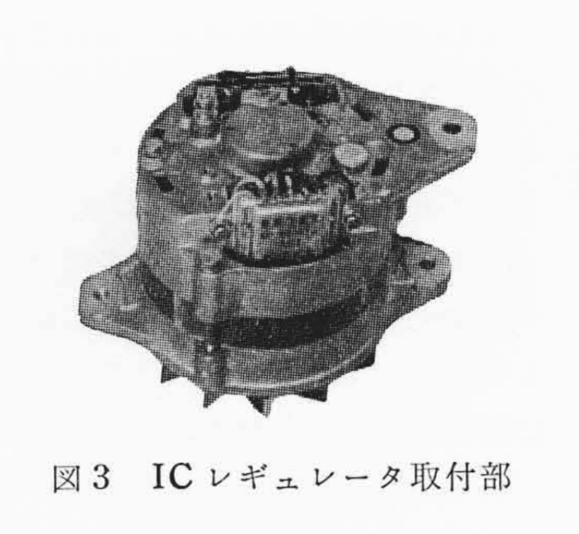
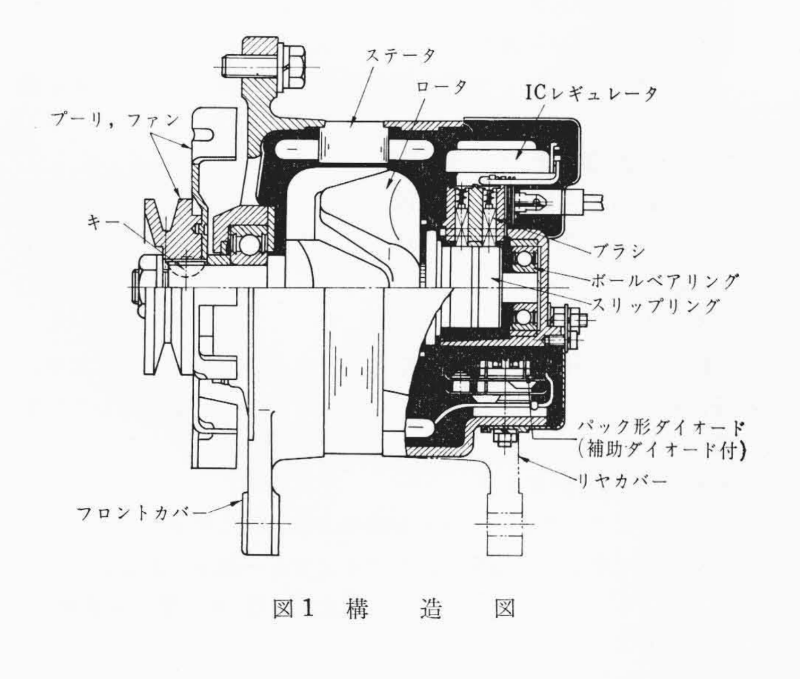
Today I turned my attention to the alternator, to see what I could learn about it, and share some of my early findings. Works cars had up-rated alternators with on-board voltage regulators, which was a departure from the S30 production cars. I've attached a few close-up photos to show how it looks in the car, and from the bench. I've also included a photo of the alternator used in the 1971 Monte Carlo - to my eye, they look similar enough to be considered equivalent, although I don't see any part numbers on the alternator, so there is no real way to be 100% certain. Without having any markings on it that I could see, I elected to disassemble it in anticipation of getting it rebuilt and ready for use. I didn't get very far before I had to quit for the day, but at least I was able to disassemble enough of it to get a picture of the markings on the voltage regulator - it's a Hitachi TR1Z-06. Based on a 1971 document I've downloaded from Hitachi's site, a version of this IC-based alternator was used in the Nissan President and Cedric, and it came in 40, 50, and 60A models. I'll need to bench test this one to determine its actual output. It appears that stock units did not have the protective black rear cover (see picture of a stock example). It was likely added by the Works team to provide additional protection to the voltage regulator.


-
Great stuff! Did you happen to record the inner diameter of one of the inlet-ports? The 73 safari 16mm print could yield some good footage. Hopefully the print survived, and can be brought into the 21st century light.
-
I also own an E-type, and I would never say that the Z had similar characteristic lines to the coupe. The E-type's primary charactristics for me are swoopy, rounded fender lines on both extremes, looooong low hood, and slightly too bulbous roofline, with too abrupt a windscreen rake. Still a classic, no question. [edit] To add, it's not unusual to have fans of American classics and such to come up at the gas station pump and mis-identify a particular car I'm driving, or not know what certain cars are. I've personally never heard "E-type" when I'm driving a Z, or vice-versa, but perhaps others are getting different comments.
-
Some thoughts about Leno's show, based on what I've seen over the years. I do appreciate Leno's role in the public space, where he endeavors to shine a spotlight on both common and uncommon classic cars - the shows he did on steam-powered cars were quite interesting, for example. That said, it's never been a show where accurate information about much of the cars he features is disseminated- it's really done more in the "variety show" style, where conversations are light and subjective, with plenty of personal anecdotes, and seemingly less homework or prep done on Leno's part beforehand. By this standard, Leno's treatment of the S30 is no real exception to the norm. I'm fairly certain they told Mr. Ataka (whom I consider to be quite knowledgeable on the subject) to "dumb it down", "agree with what Jay says", and generally work to make Leno look good. Worth noting that Leno is a bit older than he was when the show started, and perhaps not quite as sharp - not much he can do about that, we're all aging together at this point. I call it an opportunity missed for the whole series, and I also wish a few more accurate facts had found their way in to the video, as I do with most of his videos. But at least neither of the Jays mentioned the word "Goertz" (that I heard), which I consider a small victory. Baby steps.
-
Just to clarify here - based on Alan's data and my inability to find a corroborating period photo of a sleeved-nut wheel on a Works car, I'm now thinking that Works cars likely couldn't have used sleeved nuts and wheels, and that this wheel I pictured may be from some other application. I'll add: the period use of tapered nuts instead of sleeved nuts is corroborated by the images Alan and I have of early Works cars using open wheel nuts. To explain: @HS30-H 's info has resolved a problem in my mind that I could not figure out until now - namely: "is there such a thing as a wheel nut that is both sleeved AND open-ended?" For my prior assertion to be correct, such a part would have to exist. Alan's data suggests the opposite is true - the part that didn't exist in the open marketplace is actually the specialty Works wheels with tapered steel inserts. That doesn't mean that open-ended sleeved wheel nuts don't exist. I've just personally never come across one (although I could make one using a sleeved acorn nut and a grinder.)
-
Good info - I'll have to re-calibrate my own thinking on the evolution of Works wheels and their likely dissimilarity to standard issue. I spent some time looking for wheel pictures yesterday, and I could not find one which looked similar to the one I originally pictured above - entirely possible this is a non-Works Mag, and possibly not even original/authentic Kobe Seiko Mag. As an aside- I've poured over period pictures of my car before, and I have always thought that I could see open wheel nuts in some of them (which i could never understand how that could be, given what I thought I knew at the time), so I went with open nuts for last summer's shows. Pictured are the 2010 replica Mags with steel inserts, and a couple of inexpensive open nuts. Moving forward, there is clearly more investigative work to be done on my part, which is part of the fun.
.jpeg.dcb1696abb13b04e8df09deb1780084a.jpeg)
-
To my eye, just based on the harness, that looks like it could be a ZClocks restoration. I've sent him 4 clocks, and they all came back looking perfect. He typically replaces the entire harness with new wiring (at least it appeared that way). One of the boxes I sent him had a cracked vibrating fork, so he replaced it with a PCB in the original case. A great service - highly recommended. Just as an option, mine appeared to have been mounted using a pair of thru-bolts on the upper-right firewall. I modified the design slightly by running a longer bolt through from the engine bay, and tightening it in place with a locknut. Then I could just slip the oscillator on and off over the remaining protrusion, and tighten using a second nut. JDMjunkies, perhaps this will give you an idea for mounting yours.
-
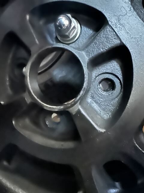
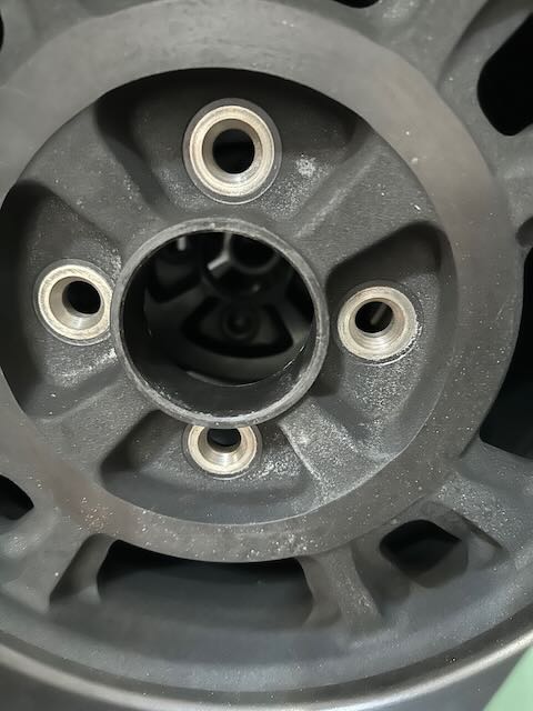
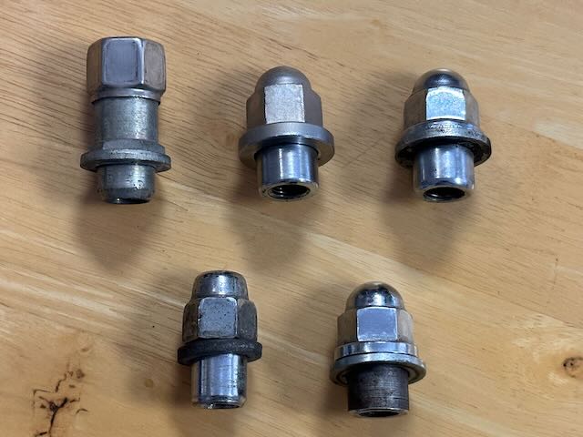
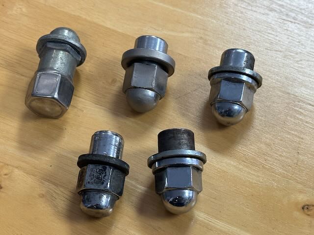
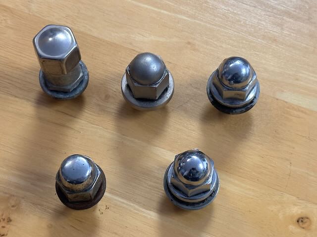
Kats, here's a little more information. For starters: AFAIK, original 7x14 Kobe Seiko wheels are designed to be used with the style of wheel nuts I've shown a few examples of, or the left-most wheel nut in your picture, with the large flat washer. Id imagine that this was designed to help spread the forces over a larger surface area, due to the fragile nature of the magnesium. I can only presume that it was determined that smaller wheel holes would not hold up to the stress of lateral forces by just using standard sized holes with tapered nuts. The 7x14 Kobe Seikos that I have would also use the same wheel nut with flat washer, and could not safely use the tapered nuts, because the holes are too big for the studs, providing minimal contact without the special wheel nuts (picture 1). I believe this wheel would be the correct wheel and (almost correct) wheel nut for the Works cars as well. As to my Works car- I've been using a 2010-era Kobe Seiko Mag replica which employs the tapered nut style, largely thanks to a steel insert in the casting which takes the bulk of the stress, and then distributes it to the magnesium hub (picture 2). It's clearly a safer alternative for actual road use, but I don't know that it's strictly "as-original", though.
-
Here's one for the Mag wheel crowd. Over the years I've managed to collect an assortment of wheel nuts which happen to fit the Kobe Seiko mags. Not all of these are likely to be dead-nuts period "correct" , but they'll all sort-of work. I've selected 5 different kinds for this post, and I wanted to get some feedback to see what others thought they might have been from. I'd venture to say that the top-middle nut is probably the most accurate, but most folks would probably not think twice about seeing the others (apart from the long one, which is probably for a racing application). Somewhat annoyingly, I don't actually have a full set of 16 of any of these, so I'll have to mix-and-match for the time being, and keep my eye out for more wheel nuts. [EDIT: So a friend of mine tells me that the right-most nuts are a close variant of 280ZX nut. And just by inspection, I'd venture to say that the lower left is an aftermarket nut.]
-
That is a beautiful wheel!
-
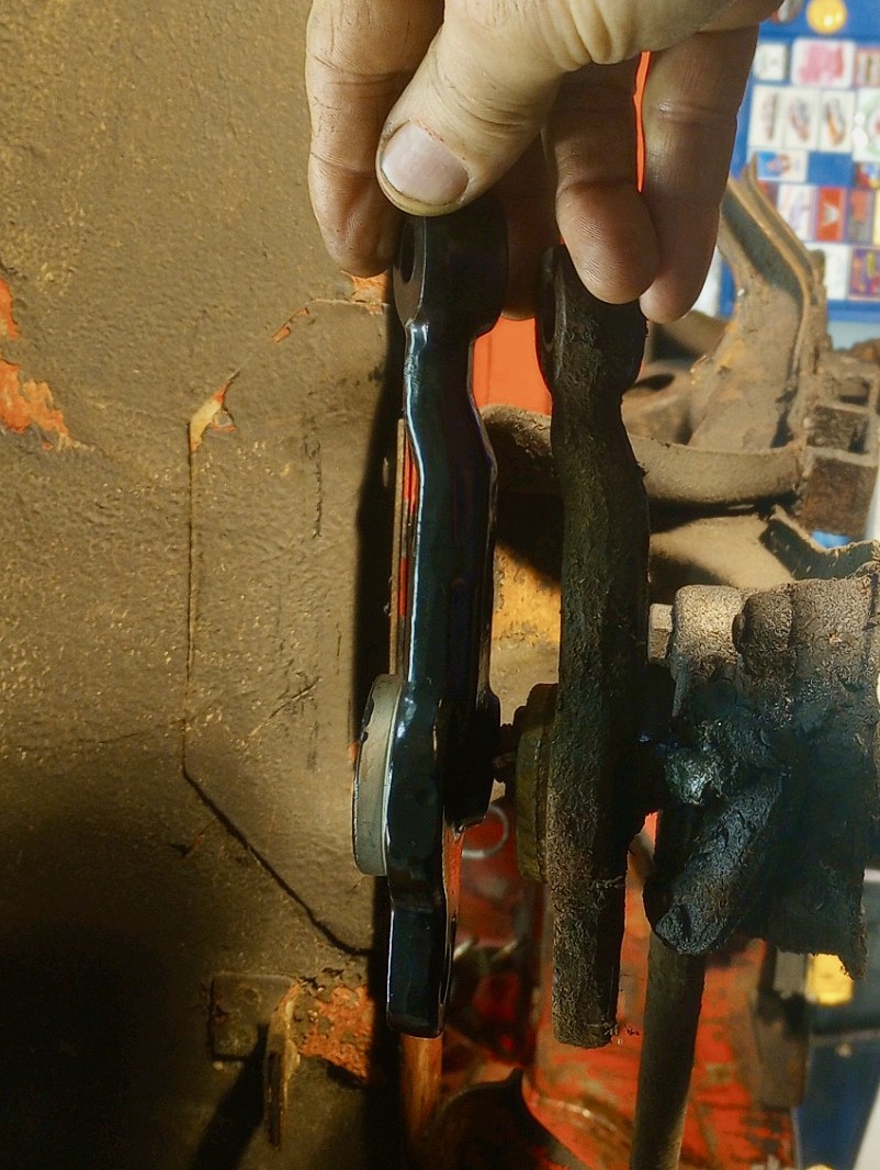
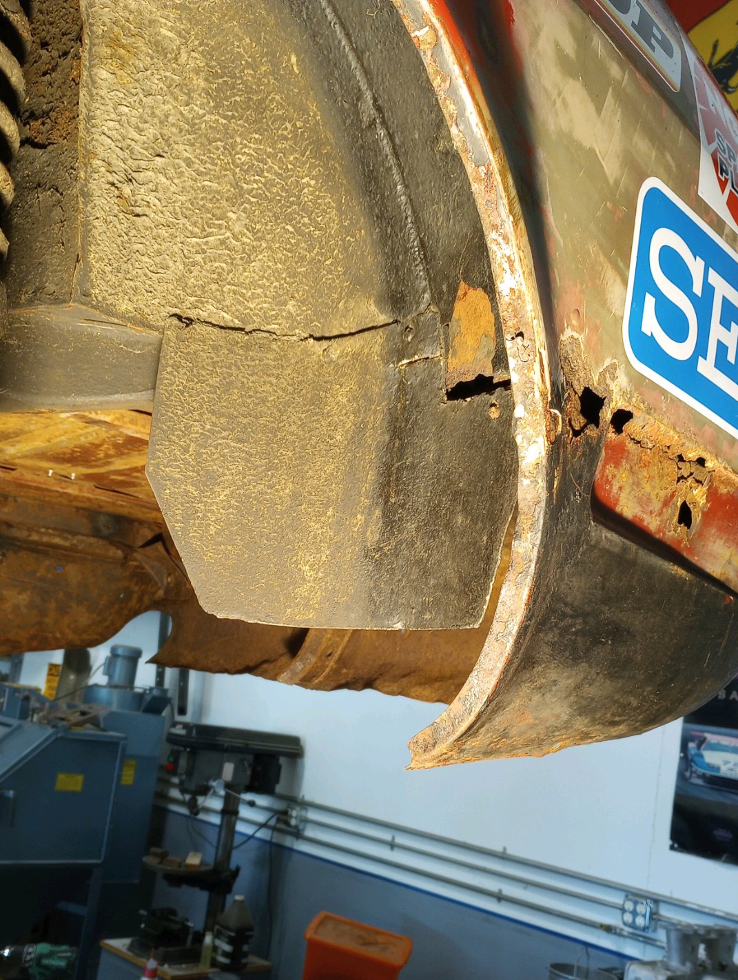
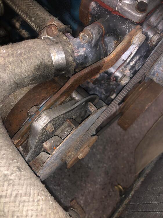
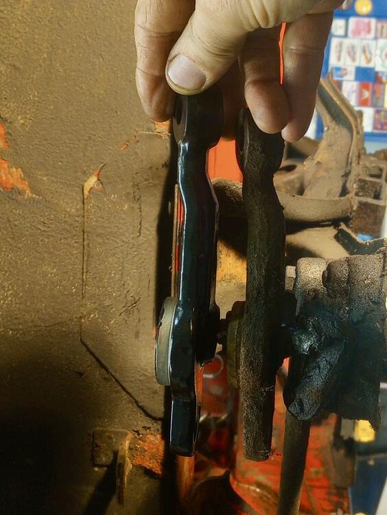
A few of the discoveries during disassembly- strengthened gearshift mount (with stock mount for comparison), shortened steering arms (longer arm on left is stock), and rear left-side splash panel - just some of the little details which escaped us earlier that we're now noticing. These are perhaps easily overlooked features, but for me, its just interesting to see the attention to detail. All these mods serve a specific purpose.
.thumb.jpeg.c9499c5e52601d778622258a0854128e.jpeg)

-
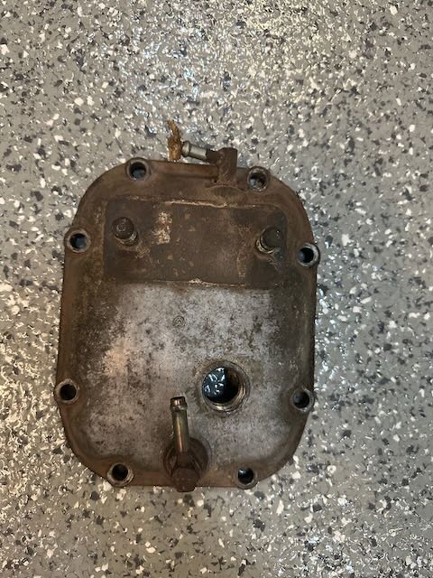
A little more on the R180 4-pinion LSD: mine arrived disassembled with the car in 2014. The mounted ring and pinion is 39:8 (from my reading), which amounts to a 4.88. I don't know yet what ratios are in the gearbox, but my sense is that I'll probably want to change the diff ratio for modern autocross use. The rear plate makes use of existing threaded holes for inlet/outlet for the diff cooler. My understanding is that the Ring/Pinion set is swappable with other early non-LSD R180 rings (but not later ones), so that part will hopefully be straightforward. As to the LSD internals: I've yet to assess the condition of the clutch packs, so I may need to swap out the LSD with something else in the interim, until I've got the parts I need to complete the overhaul. For most uses, I doubt I'll notice the difference.
.jpeg.870b43ed1b5307be6bef857463c38436.jpeg)
-
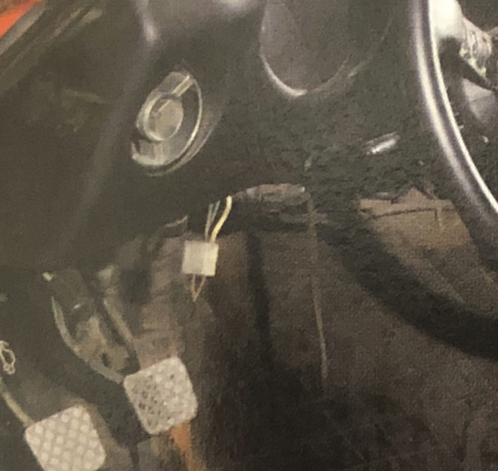
Something else caught my eye in @kats photos, namely this dangling 6-point plug (pictured), presumably taped to the steering column of the '73 car. I'd imagine it's designed to plug into the ignition switch in place of the standard harness, and potentially make the car drivable in "hobble" mode, or at the very least, to bypass some of the wiring in order to debug something engine-related. I also had one of these in my car, taped in the same location, with a bare-bones collection of stand-alone wires leading to the fuel pumps, and I believe the starter and alternator (and perhaps more - I'll have to reconstruct my notes). I was fairly certain at the time I removed it that this was something wired up by a prior owner, and not original Works, based on what appeared to me as haphazard wiring. Seeing this dangling plug in the same spot on the 73 car makes me question my original assessment. I've often heard "dual wiring harness" being used in descriptions of Works cars, but I always assumed that people were referring to the 2 fuse boxes, and not the presence of a "redundant wiring harness". More study will be required- any further thoughts?
-
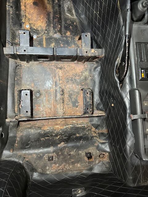
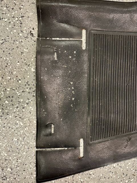
@kats Thanks for the scans. The steel plate on 8D-433 shades our view of the differential area. Without a clearer photo, it would be hard to tell what is in the cavity between the tank and the differential, where the diff cooler is situated on my car. As to the extended seat brackets: that detail is also present on my car (pictured). I don't know if these extensions were also present on LHD Euro delivery s30s, so I can't speak to how uncommon it is. The rubber mats were carefully altered to accommodate them.


.jpeg.08ac945f60af8c179aa5dd50a566c0a4.jpeg)