xs10shl
Free Member
-
Joined
Everything posted by xs10shl
-
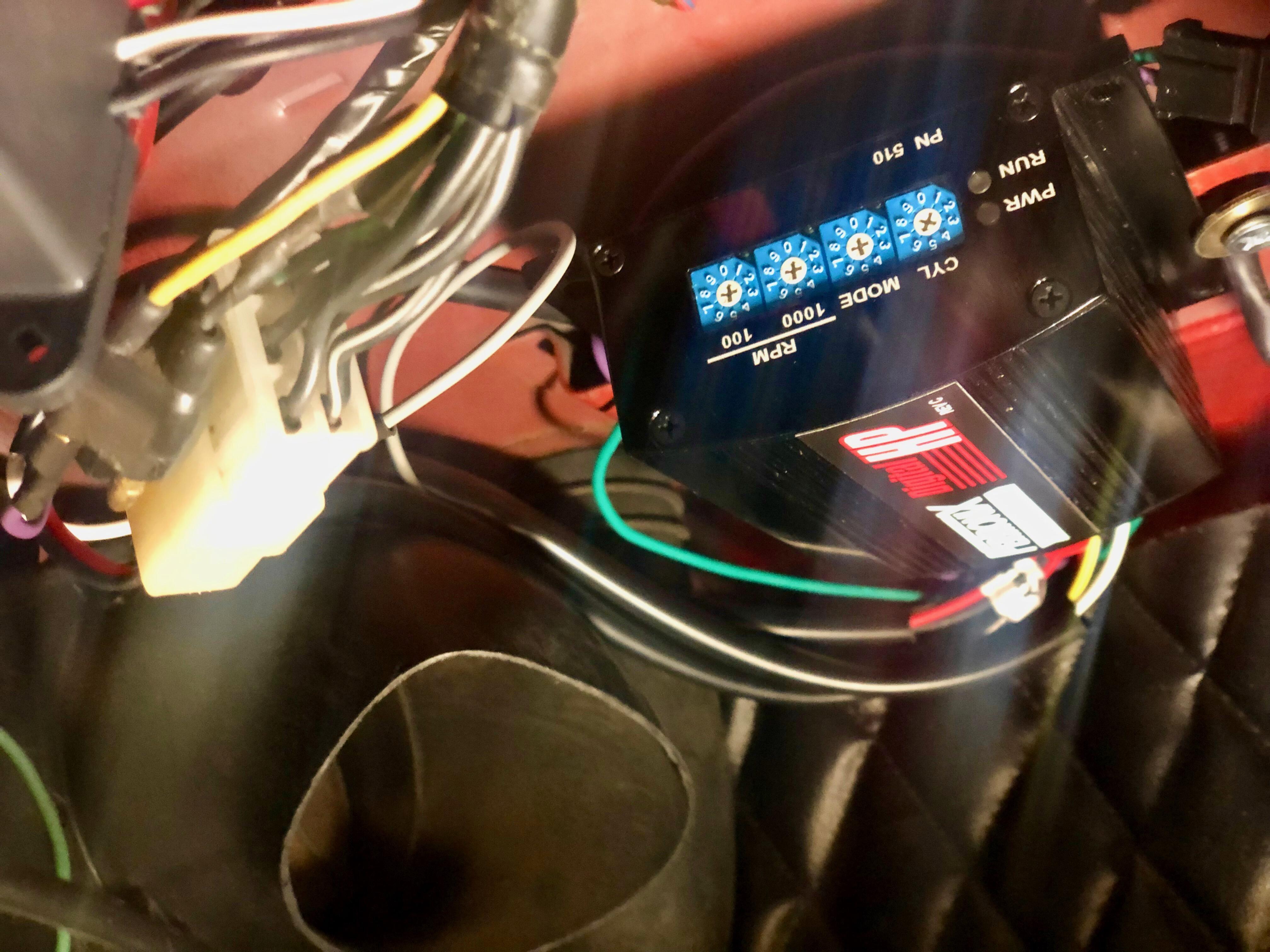
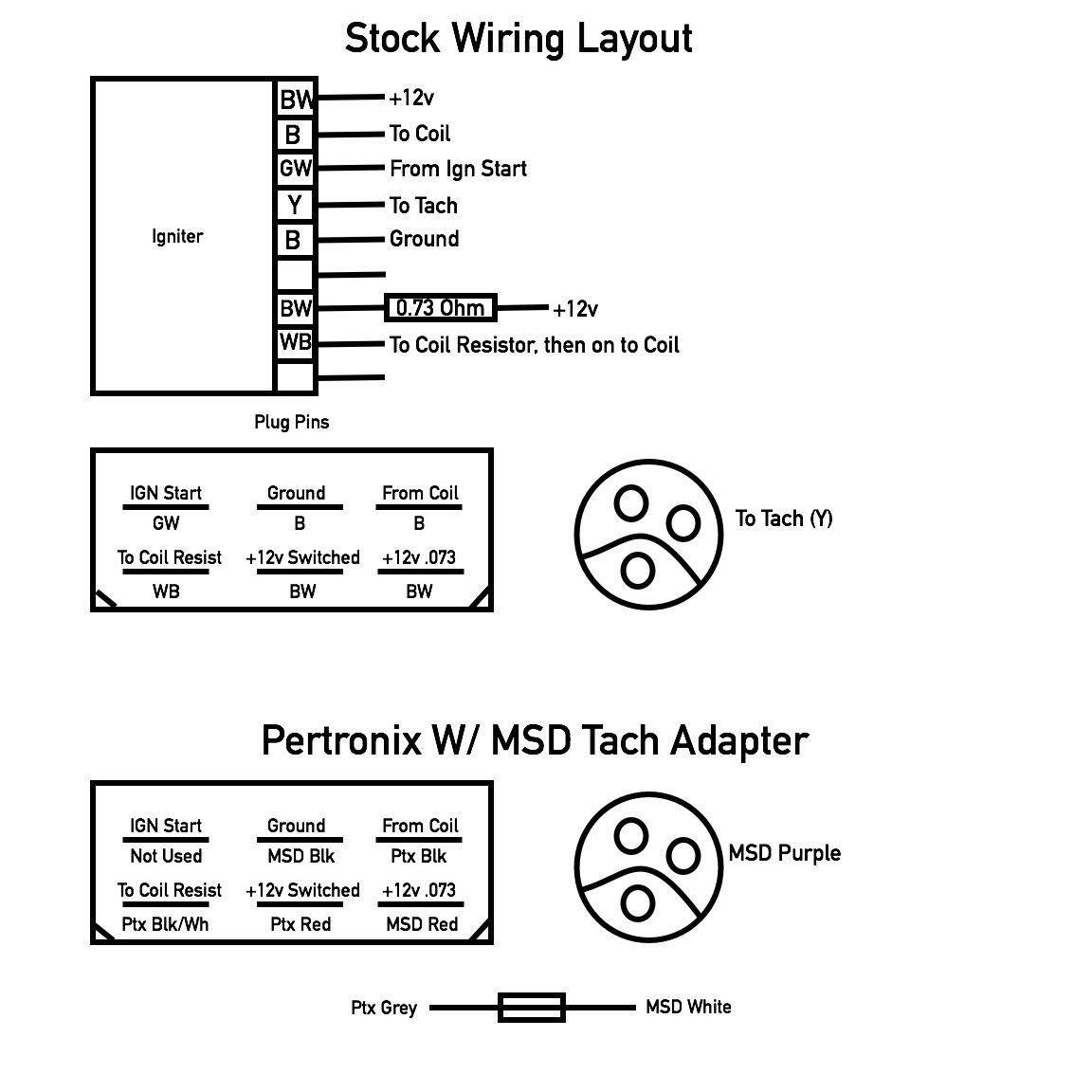
Here's my solution for replacing a PS30 Stock CDI with a Pertronix HP box, using the stock harness hookups. It fit neatly on the existing bracket, with the aid of a pair of "hold-down" fender washers. To get the Tach to work, I used an MSD Tach Adapter, as I could not get the Tach to respond to any alternate configurations using just the Pertronix setup alone. The Tach loses accuracy as the RPMs increase, with a 700 RPM difference at red line (reading 6800 at 7500 RPM actual) but for now, that deficiency will have to suffice. The other change I made is to remove the in-line coil resistor from the circuit, which is a simple matter of removing the electrical tape, removing the 8" wire connecting the resistor and the coil, and storing it for later use if needed. I'll probably just mock-up two dummy wires and re-tape it to the main harness to give a stock appearance. Of note, I think one can hookup the stock distributor trigger wires as well, but a prior owner had removed a good chunk of the wiring already, so I just used modern purple/green wires, bypassing the harness hookups. edit: in thinking a little about this tonight, I may consider adding a jumper to "Ign Start" to the +12v switched input of the Pertronix, and monitor the results. The car starts fine without this feature, but it's a little awkward, as some power is disabled during cranking (by the design of the ignition switch), which causes the Tach to jump twice.


-
I think I recall reading somewhere that one of the early Nissan design/studio teams was numbered 903RTZ. ...I'll see myself out. 😀
-
Thx Alan - all sorted. Resistor was still hiding in plain sight. The drawing made it appear that it was somehow nearby the CDI Igniter, as opposed to clear across the car.
-
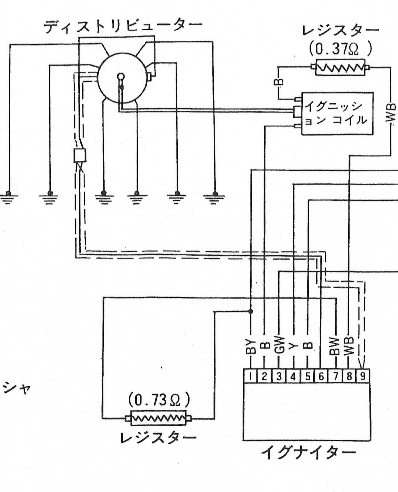
Apologies for the interjection - I'm fiddling with my CDI setup, and in looking at the schematic, I've come across a 0.73 Ohm resistor which I cant find on the car. In addition, my wiring loom doesn't have a Black/Yellow (+12v from ignition) and a Black/White wire (as shown in pin 1 and 7), but rather 2 Black/White wires. Pin 7 is basically powered from the same supply as pin 1, with the addition of a resistor. The car is an early 1970, and this diagram is from 1971. Was there a change introduced, potentially to ease the number of issues with the CDI? These two +12v wires are essentially un-fused (in both cases), and come straight from the amp gauge, through the ignition, and into the CDI unit, so I can see where there would be a "dead short" potential.

-
RE 270: if 240Z was truly inspired by "project 270", it does make one wonder if there was a design on the board for a 450cc capacity per cylinder at one point. or I suppose, even more radically, a 300cc 9-cylinder. Kidding about that last part.
-
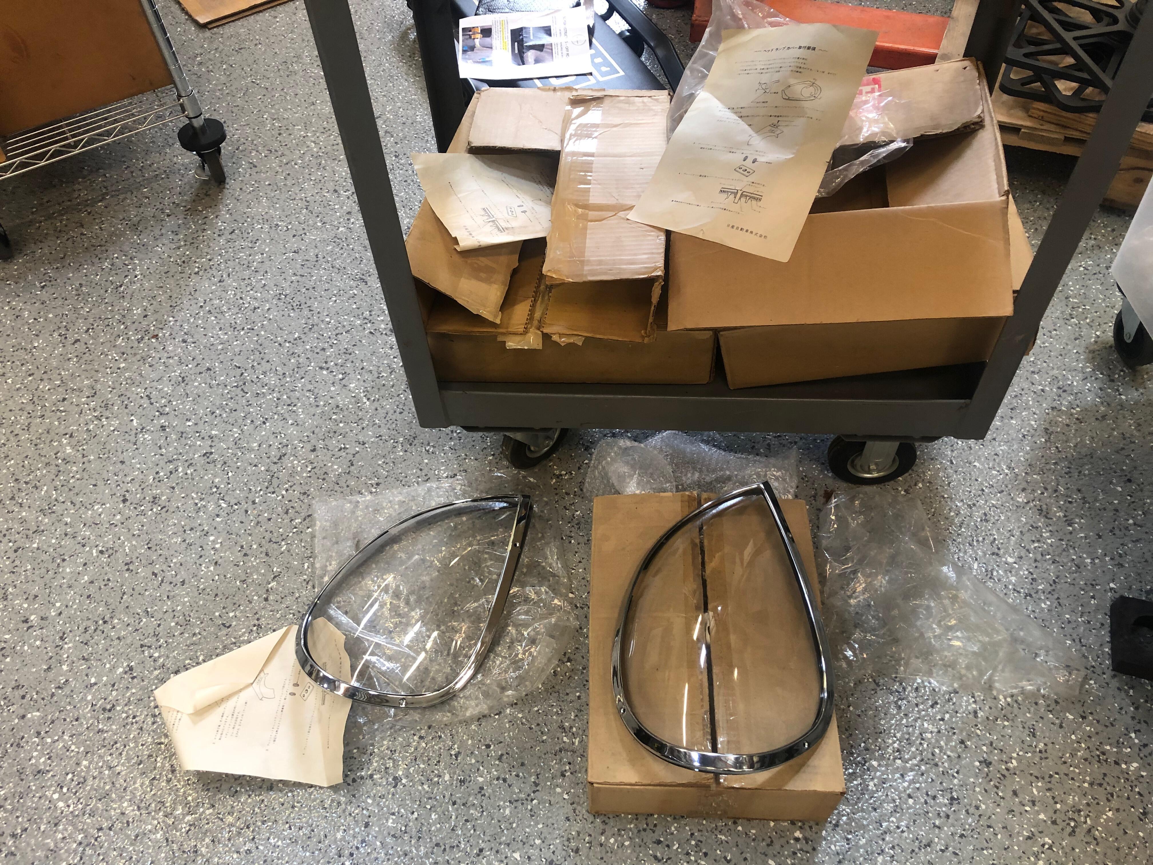
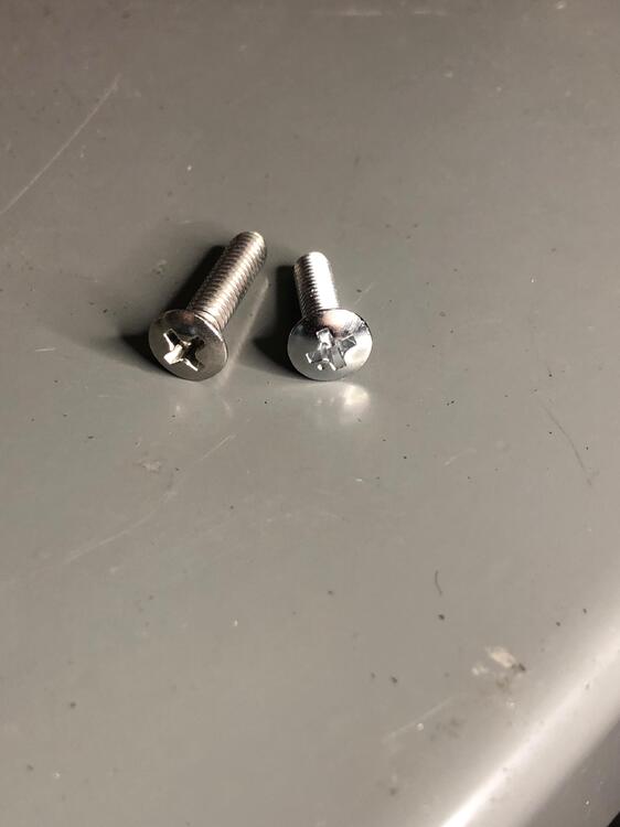
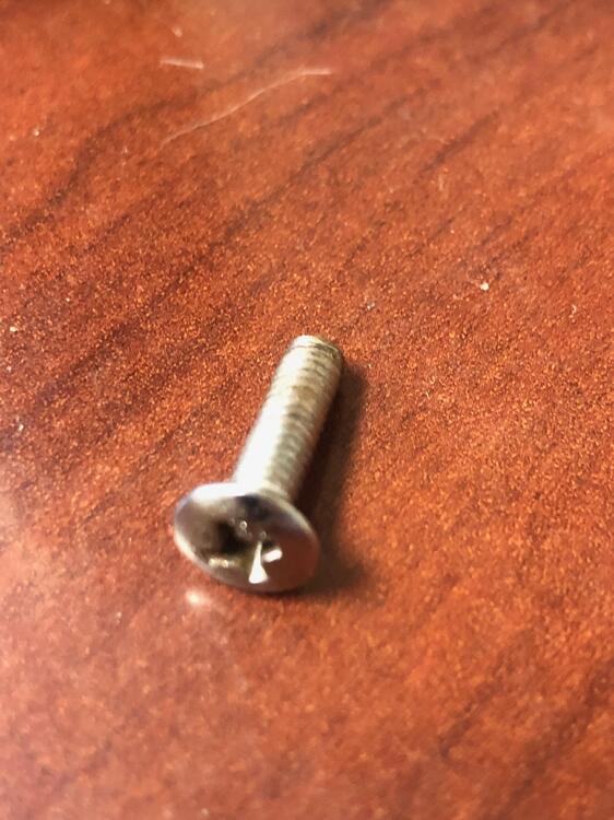
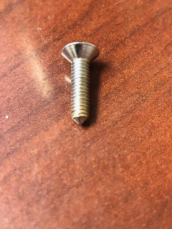
the epoxy trick is a good one that I should have considered. RE screws. I can't say for certain whether my screw bags hadn't been swapped out at some point-- or perhaps even that these covers are simply decent replicas in an original boxes, as opposed to genuine Nissan. Thankfully, they look good enough for my current need. I also could not find chrome oval machine screws that were as broad as the ones I had. I've included a picture of the screw that was in the bag, as well as the longer stainless screw I used. Perhaps you can add your thoughts. As Murphy's Law would have it, I found an Astro 1441 Metric rivet kit this AM which I purchased, a mere 5 days after giving up on finding one, and installing SAE rivets. I think the SAE rivets have a slightly larger diameter, so I wont have to consider tempting fate by attempting a re-install of the metric rivets in place of what I have now. Edit: just for kicks, I examined a screw from another set I had, and it looks to be genuine, when compared to the other hardware I have. It's the only one that has a pointed leading edge. Unfortunately, I only have this single screw.
-
Kats, i was certainly thinking of the time you posted your photo years ago as I was carefully drilling holes! How nice it would have been for sets like these, with captured nuts, to be more widely available. Of note, I remember a thread where we discussed these hole positions as shown on your buckets, and that they may represent an "early" pattern version. Then some time later I recall seeing a photo of a very early car which showed the other, more common style of pattern (similar to what I'm using). Was that ever really fully decided one way or another- one pattern was "early-style", and the other "later-style"?
-
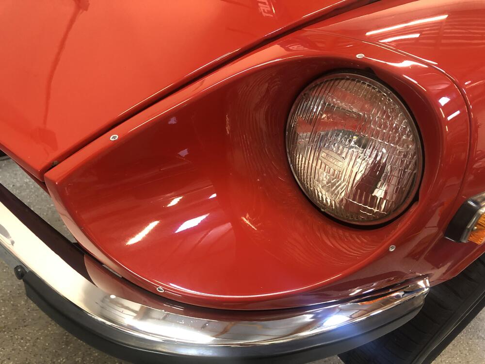
Final initial thoughts: I've heard before that it's best to install these covers with the chrome surround in mind, which is the method that I attempted first. In the end: other than to make sure the chrome piece basically fit and aligned with the cover, I did not find it all that useful to fit everything while trying to hold the metal surround in position, in addition to holding the cover. Since the metal is flexible, I figured that I could more easily massage the chrome to fit around the cover, vs letting it dictate where the cover would be installed. Perhaps I got lucky this time- others may have alternate tips and tricks to share. The end result is, IMHO, a superior and easier-to-implement solution to the "3-hole" mounting tab that Nissan provided. As as I said before, no one will ever know, because I'm not telling anyone!

-
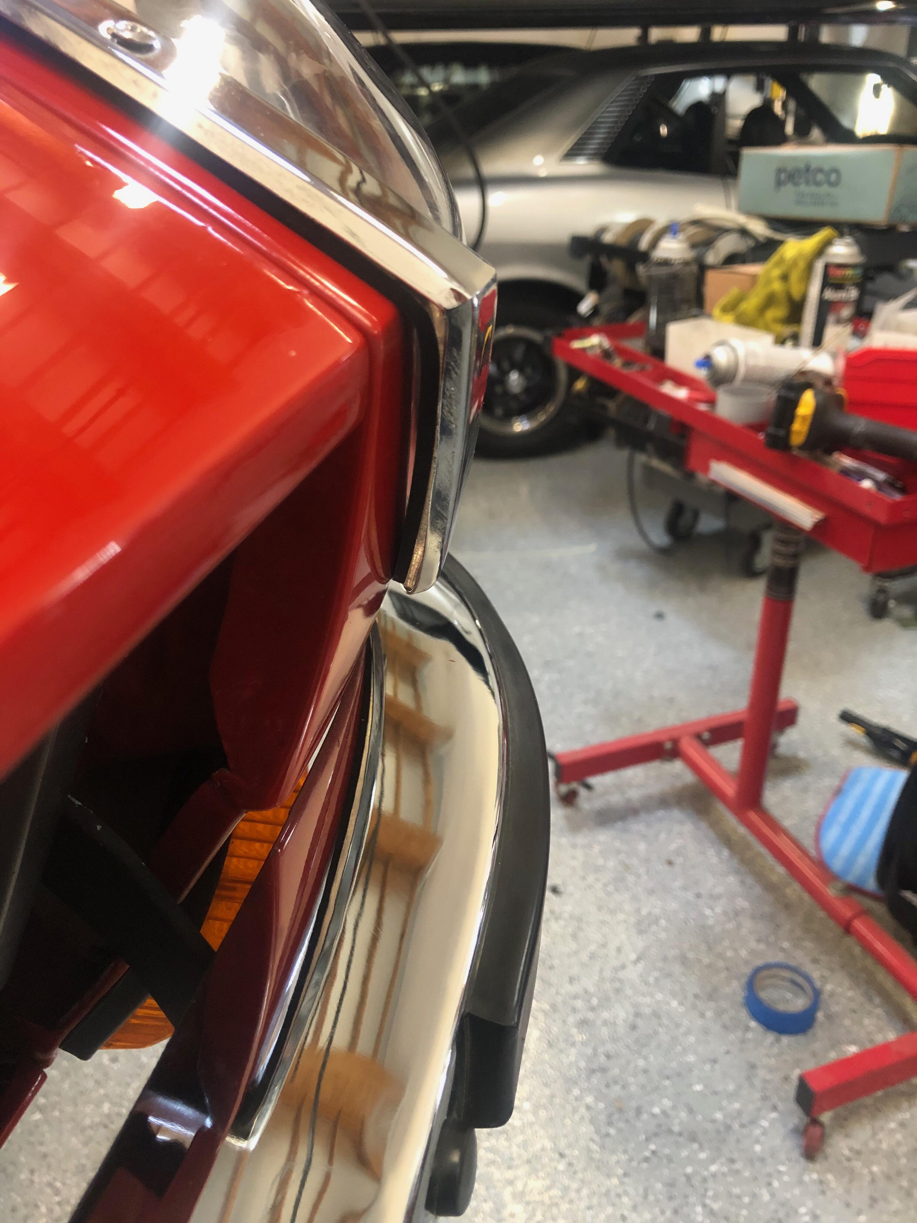
Another side trick which might not be all that helpful to everyone is to have more than one set of headlight covers to choose from prior to installing. I'm fortunate to have a few sets which I've collected over the years, and although they appear to be largely identical, I found that I could get one of the left-side covers to fit more easily than the others, so that's the one i ended up using. After speaking to my mechanic about this, he corroborated that he had the same experience. I'll just hope that the remaining covers will fit well on whichever future cars I hope to use them on!

-
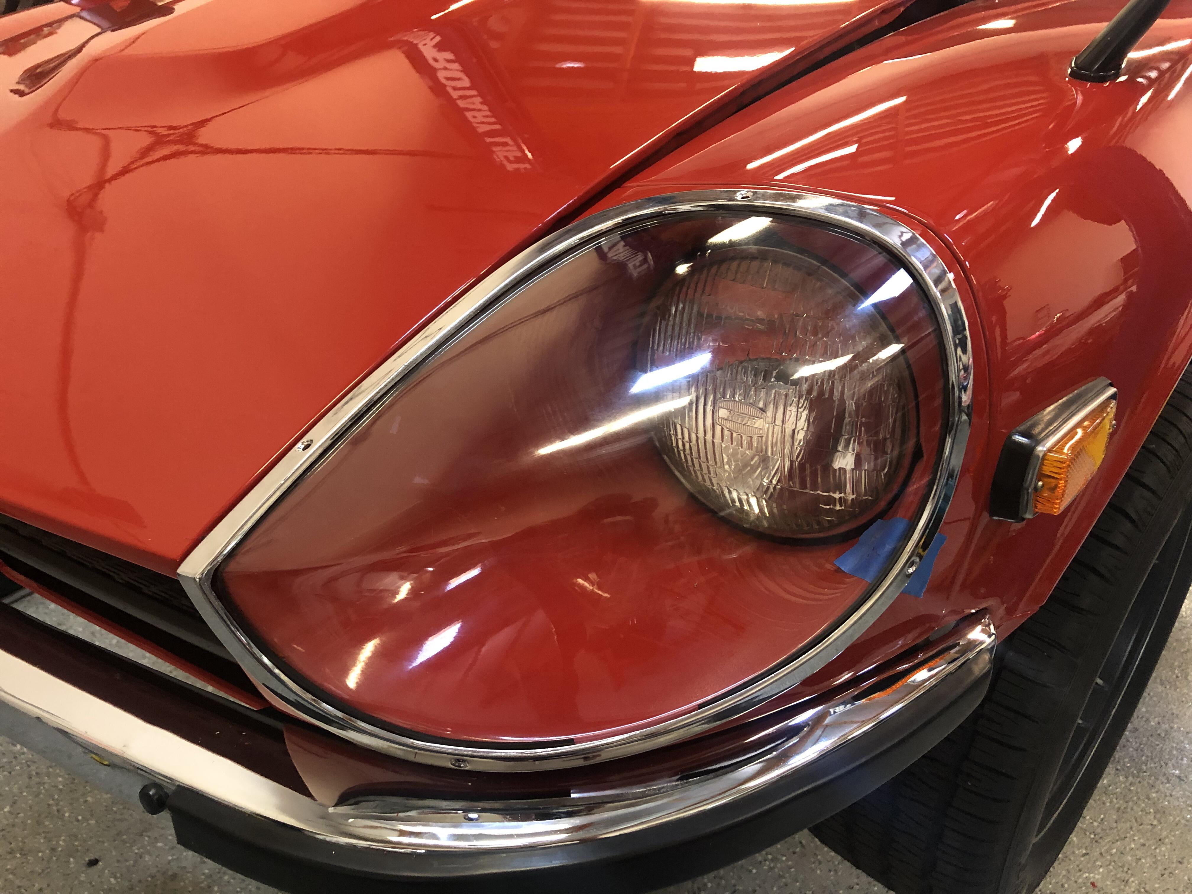
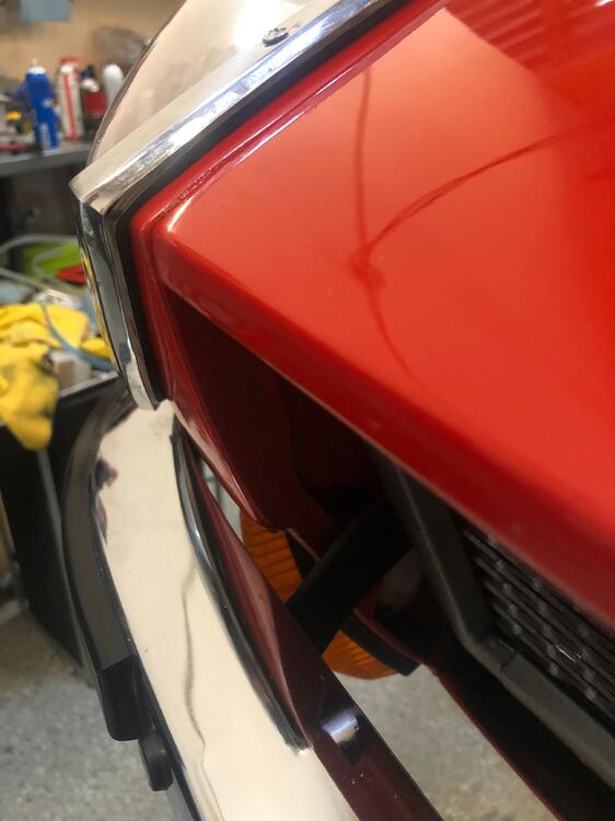
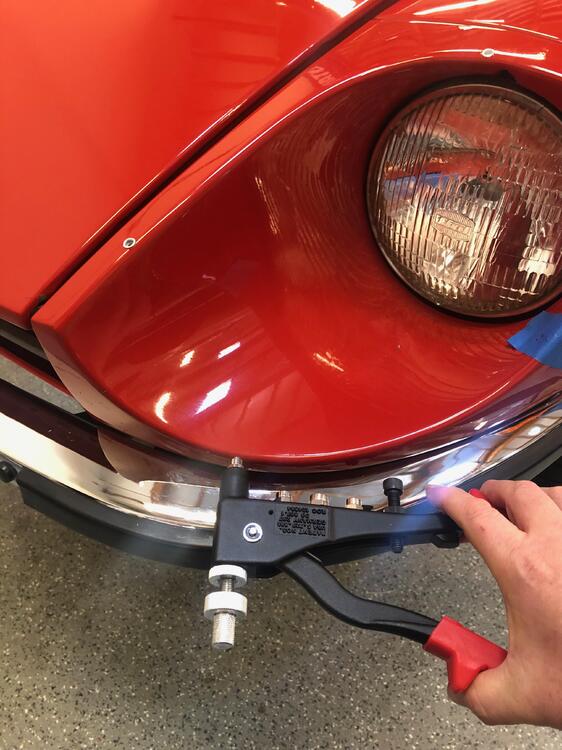
Contrary to what the above photos appear to show, I went around the bucket by drilling one hole at a time, inserting the rivet, and then re-installing the plexi cover, making sure that the remaining holes would still line up. On the right side of the car, i started with the front-most hole, next to the bumper. On the left side, I started with the top-front hole, by the hood. Of the two methods, I found it would be best to always start with the front-most hole by the bumper, as that seemed to do a better job in "sucking the cover" up against the sharp ridge on the nose than the other method did. As a result, the right-side installation is completely tight all around, and the left-side installation is off by perhaps 1/16", which is enough to reveal a tiny gap between the cover and the bucket at the front edge.


-
I'll share some tips and tricks that seemed to work well for me along the way. The first tip is to go REALLY slowly. Measure and mark 3 times, then go do something else non-stressful. Then come back and check again. Only then to you start drilling. I started by laying down a 1" piece of masking tape at the approximate center of each mounting hole. I then placed just the clear cover over bucket and massage it around until it appears that all four mounting holes have zero daylight - that is to say, when you look through the hole opening onto the metal, you see only masking tape. After I was satisfied that all 4 holes would be located as far away as I could get them from each edge. I began to drill one hole - first with a 1/8 bit, followed by a 1/4 bit, which was the right size for the rivet nut I was using. CRITICAL: use brand new metal bits that you just purchased at the hardware store!


-
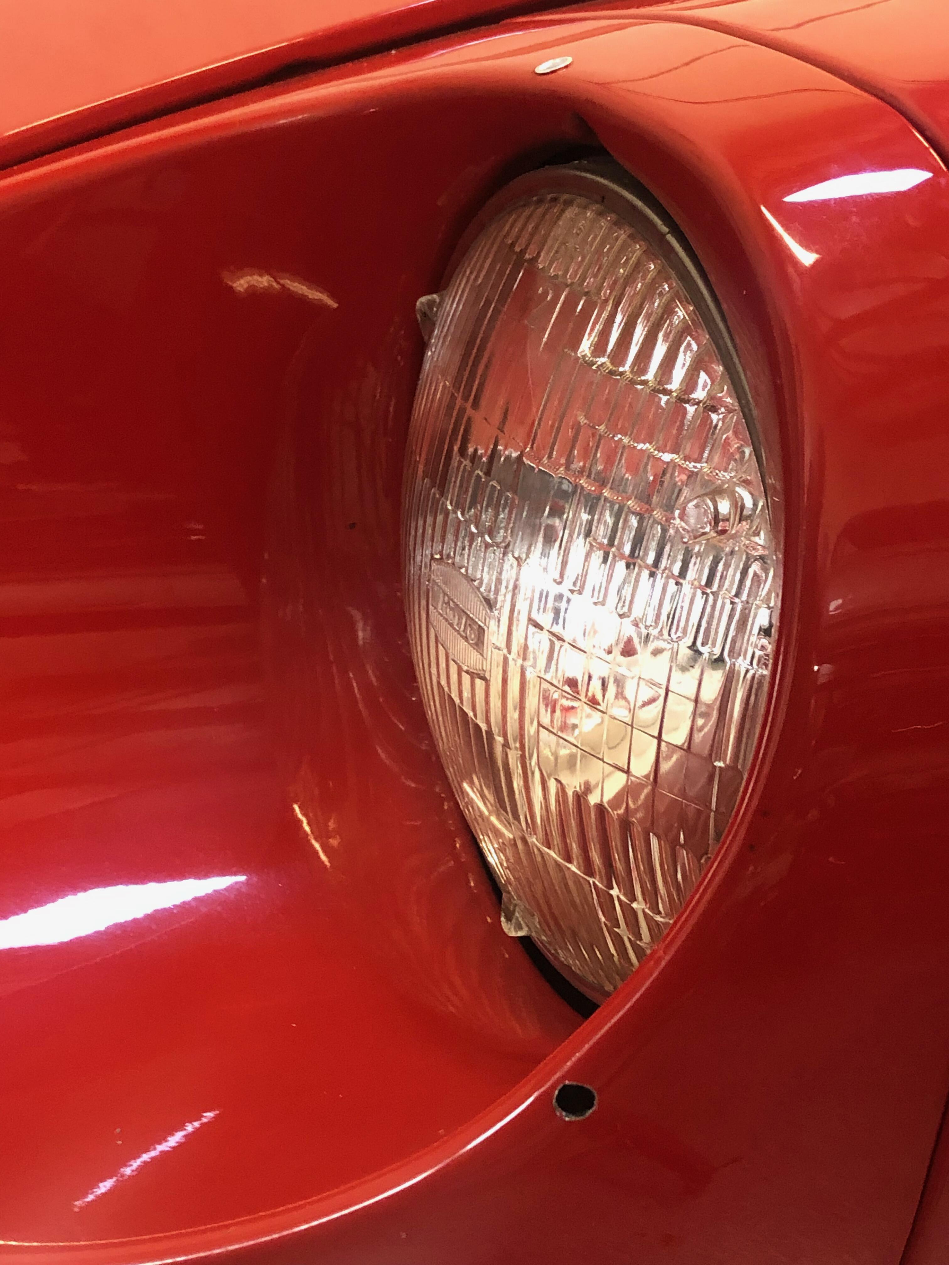
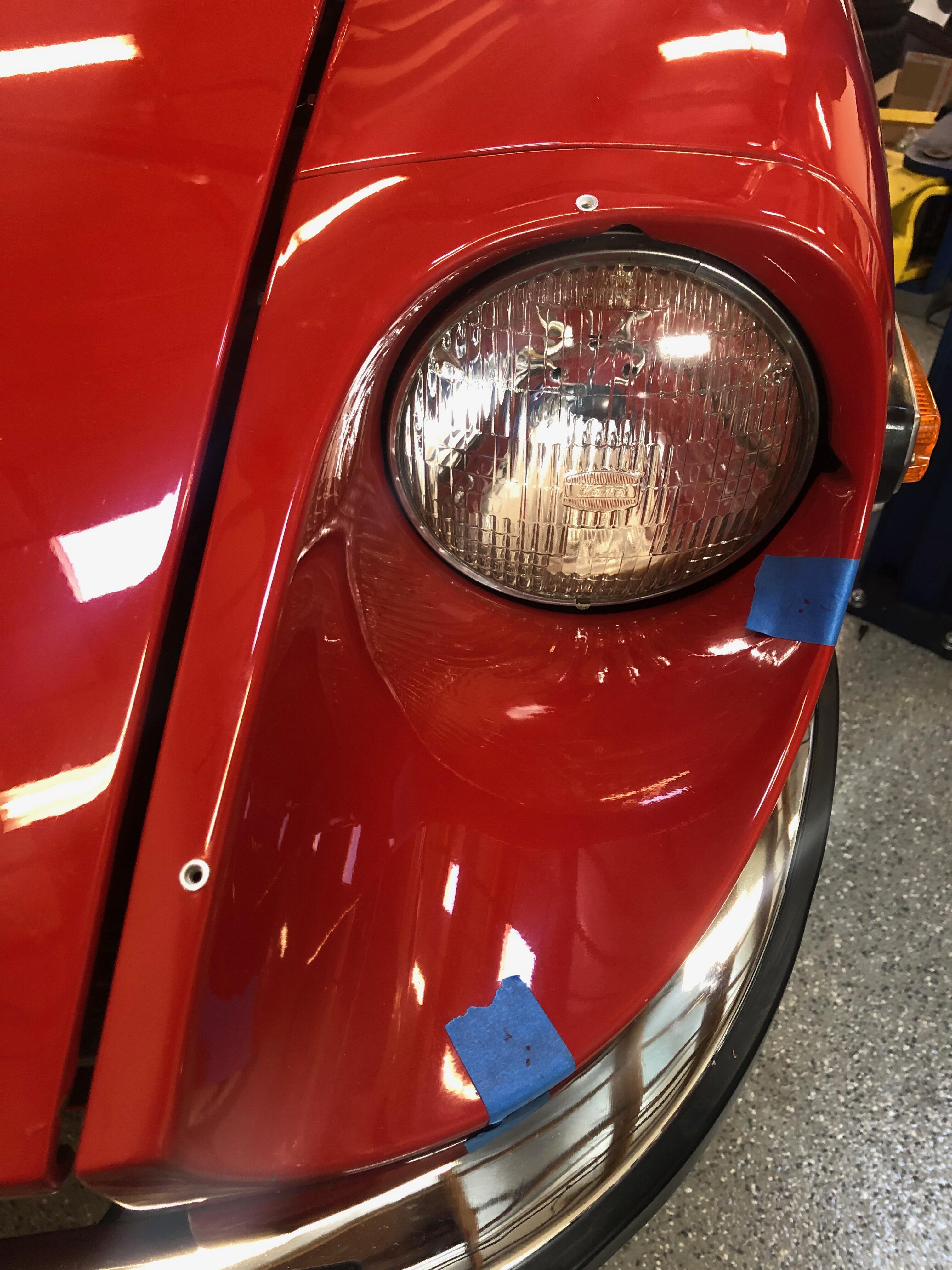
The basic cheat is to discard the dubious supplied mounting hardware (or just put it away for the next sap who wants to "do it the right way"), and go with aluminum rivet nuts. You'll only need to drill a single hole per mounting screw, and although it is a somewhat larger hole, IMHO it is a cleaner install that allows you to use the car without the headlight covers in place without looking too unsightly. I used an old SAE rivet kit from Astro that I had lying around (number Astro 1440). Regrettably, this kit and the metric kit (Astro 1441) has been discontinued, so after weeks of trying to locate a metric version in order to use the supplied finishing screws, I gave up and went with 8/32 stainless hardware and aluminum rivets, which had a nearly identical size and appearance. The car I was installing them on is a January 1970 car, where an earlier owner had replaced the fiberglass buckets with steel ones. Given that this was already "non-stock", I felt that there was little concern about keeping the rest of the headlight install "stock", so long as it LOOKED stock. Thankfully, no one reads my posts, so this little secret will be mine for all eternity. Here's what the finished rivet installation looks like.
-
Those who have attempted installing an s30 headlight cover with chrome trim probably can tell you that it's a bit of a cluster. The moldings are not all that great and/or uniform, and there always seems to be an alternate positioning on the bucket that yields, at first glance, a better fit, but ends up causing problems with either one of the mounting holes, or creates a larger-than-desired air gap elsewhere on the cover. I'm here to tell you that after my first install, I don't have the answer for you. But I do have a cheat which seemed to make the installation a bit easier and cleaner. It yielded one decent fitment, and a supurb fitment. I hope this knowledge will help prevent others from screwing up their headlight buckets during their installation attempts.
-
All the period Works 240ZR pictures that I have of perhaps 6-7 LHD cars show that the LHD Works cars sported consoles with left-side handbrakes. Period pictures I have of RHD cars naturally show the handbrakes remaining on the right side. Perhaps there are exceptions to this protocol, but I am not aware of them personally.
-
just an update on the Z432 Airbox, and my suspicions that it was suffocating the engine at high RPM - I have been driving the car for a few days with the airbox filter connected and dis-connected (by removing the tube between them), and the performance increase for the disconnected setup is profoundly noticeable. There is more research to be done re: filters and jetting, but I was actually quite surprised how much better the car performed above 5000RPM without the air filter connected. The filter is fairly new, so I may try something else in it's place next.
-
Lots of great details in that cutaway. Also a few inaccuracies for car #62: brakes shown are vented disc with single piston calipers. And the period photos that I have of the doors do not show pockets, but that may have changed for race-time. And I'm not sure what that block hanging rear of the gas tank is supposed to be - a skid plate?. I find these changes curious, because so many other exact Works-specific details are shown correctly, which means to me that the drawer had access to accurate photographs, and perhaps the car itself. i wonder if these details are taken from 8D-420 (or similar), and they simply added the Monte Carlo plate for effect?
-
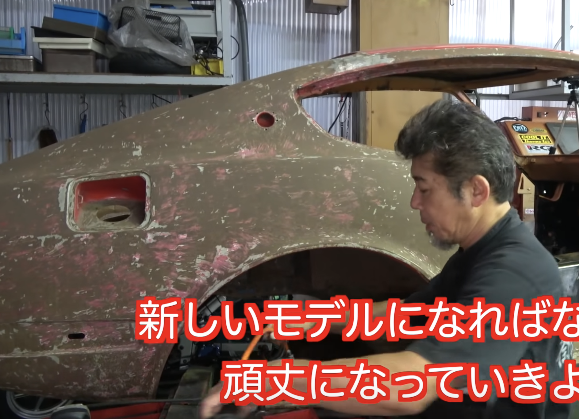
I found the Z432-R restoration video particularly interesting, in that it shows an interesting body panel makeup unique to this Z432-R (and perhaps other PZR shells as well). We see some early-style stampings such as the firewall and perforated trunk-area behind the seats, as well as no cross-floor bracing behind the seat mounts, which I think was a very early feature. And below we see later-style rear 3/4 panels. These PZR shells were truly custom. Lots to absorb!

-
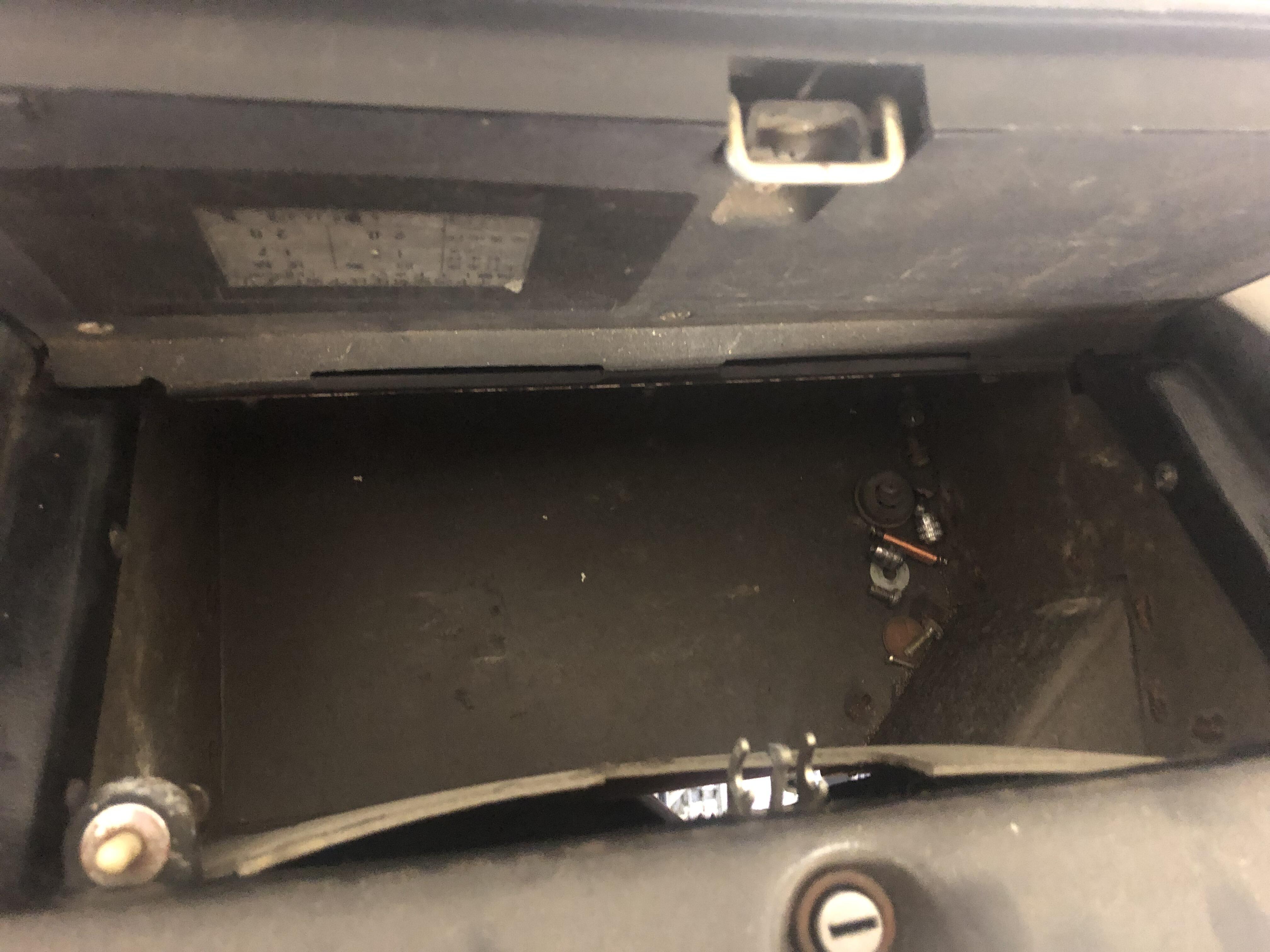
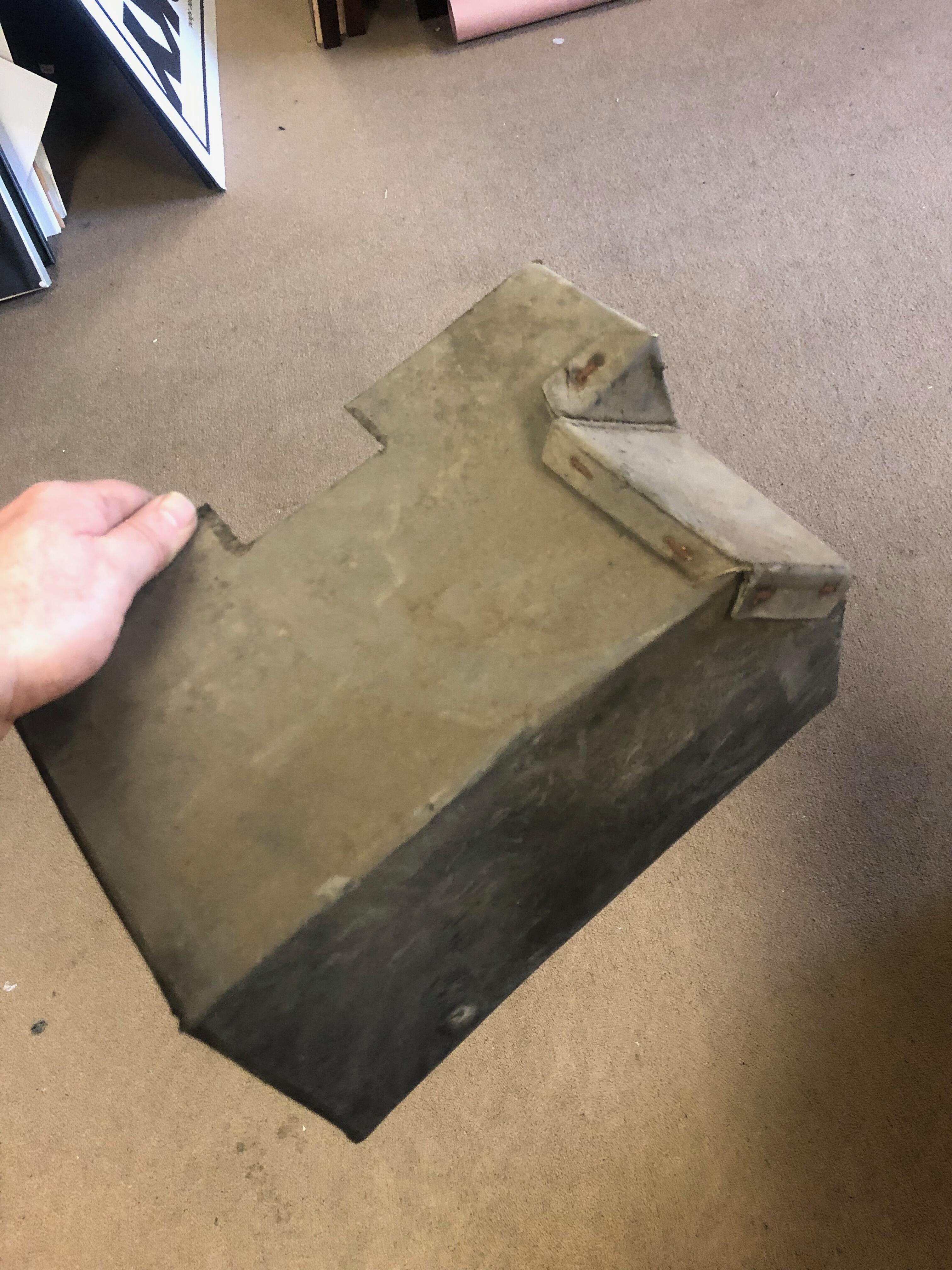
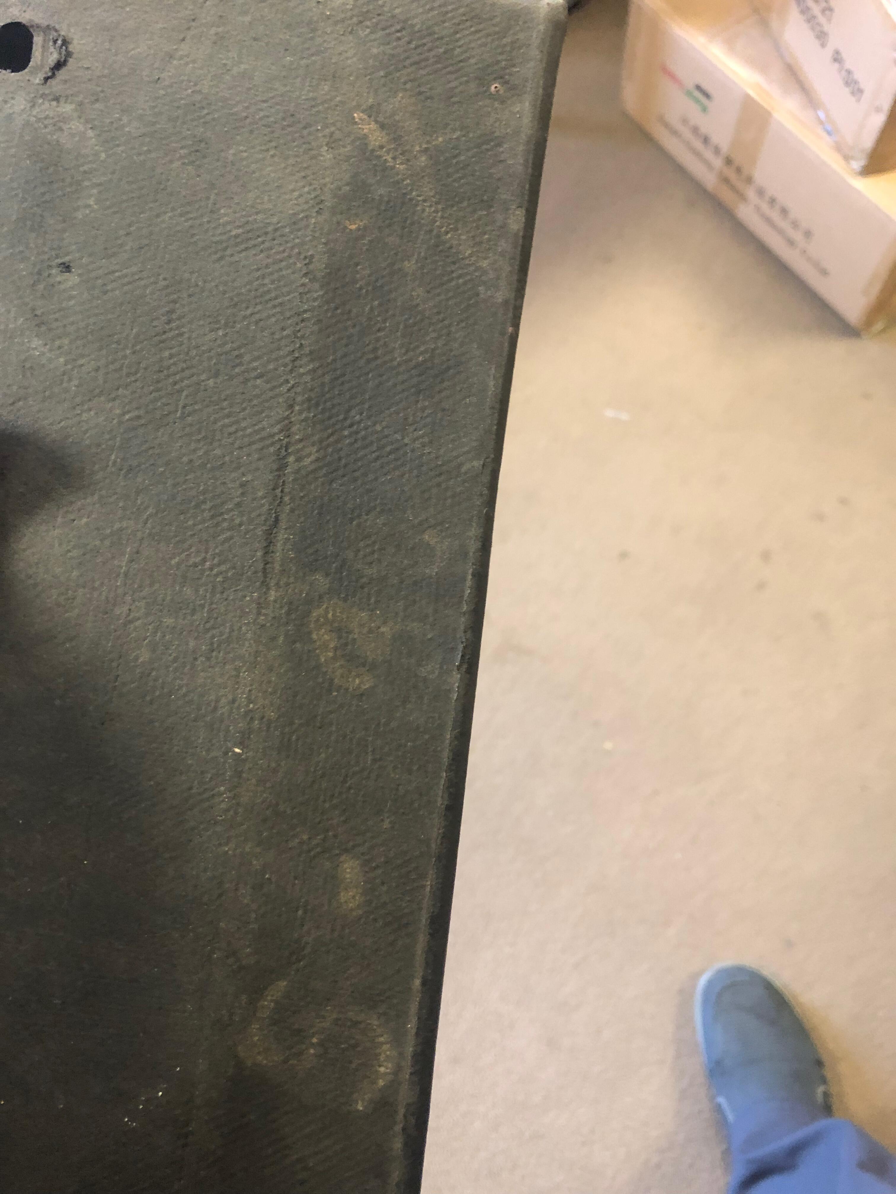
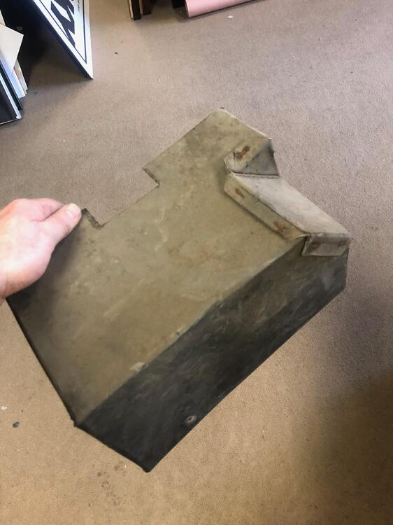
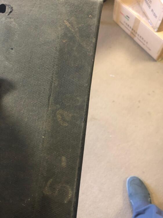
Fortune smiles. I remembered I have a spare S30 dashboard from a car in the 1200's (as I recall), and the original glove box was intact. Seeing the two boxes that I have side-by-side, I feel that it's likely the glove box I mangled was a high-quality replica (staples are black, among other tell-tale signs), and the intact one is authentic. Pics of the faint lettering from the authentic glove box attached.

-
Perhaps someone with an unmolested pre-March 1970 240Z can also chime in with a glove box photo. It appears that Nissan wised up around April 1970, and replaced the "handed" glove boxes with a universal one that fit both dashboards. So the corollary to this is that if you have a concours S30 restoration dated roughly pre-April 1970, looks like you'll need the special "handed" glove box. So I'd better get on with gluing mine back together....
-
CanTechZ - Great! Thank you for sharing! I can certainly use this.
-
We examined my later 1970 S30 Z-L glove box next to a 240Z glove box, and they appeared to be identical, with notches on both sides. I think my Z-L glove box was original, but do not know for sure. It does have factory AC, so the rules you stated would apply. I cant remember the serial # offhand, as the car has been under restoration since I purchased it, but I will look tomorrow. I'd still guess that Nissan switched to a single-style glove box at some point during production, for both LHD and RHD cars, so that they were the same. Bummed to hear that I mangled a rare piece of cardboard. I'll have to get some material and make a replica - shouldn't be hard to do.
-
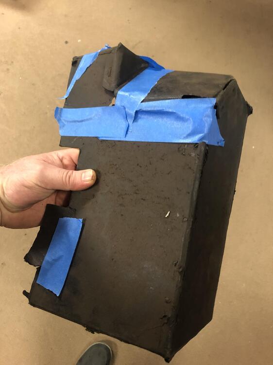
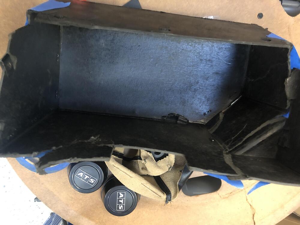
Slight tangent. Here’s a glovebox which I butchered while replacing my rally clock. I noted that it was RHD-only (single left-side notch) whereas later ones I’ve seen are notched on both sides. Not necessarily Z432-specific observation, but I was wondering if that was true with the early cars, or if I’m looking at a cheap repop with only one notch. these seem to be fairly straightforward to replicate, yet I have not seen a source for them.
-
The factory competition cages used "7" bolts to mount? With the blurry pictures I had available, I interpreted the markings as a "9", and spent weeks getting those assembled. There are only four "9" bolts with the right thread pitch per car, so they were a little hard to come by (*Hard* - see what I did there? 😀)
-
This makes good sense - a very straightforward and reasonable explanation.
-
I can't wait to see the end result of your efforts, Alan! Apologies for geeking out: Notice also on the previous photo you posted that the other fender has a "Fairlady Z" badge and no headlight covers originally, and then finally (at the Racing Show) what appears to be a "DATSUN" badge, covered headlight, and if i'm not mistaken, a tiny circle in the front of the scoop, indicating the possible presence of a defogger. And yet at this point, not yet having the front-facing headlight change. Also of note, is what appears to be clear lenses for the running lights. It's great to see how the development progressed. As to the left fender, with possible accident repair vs. intentional omission: I'd venture to say that both are possible. Perhaps the left side marker was omitted intentionally at one point, either before of after a possible fender-bender, just to see what it was like. With the dual-bulb driving light, One could easily rewire it to use one bulb for running light, and the second one for turn signal. (I'll tip my hand here a little bit, and mention the possibility that some Works harnesses may have used the 4-pin connector for the 2-bulb driving lights instead of the 3-pin, even though only one bulb was wired up, leaving the parking light unwired. But perhaps I'm overthinking it.)