JohnnyO
Free Member
-
Joined
-
Last visited
Everything posted by JohnnyO
-
 Thanks Jim. Looks like I'll be dropping the tank, again. I received the evap tank a week or two ago. Sorry I didn't get back to you on that. Looks great and I got it installed without breaking off any of the nipples and no more dents!!!!
 -
Where does the ground wire get bolted to? It is the one that is attached to the fuel sender wiring bundle and goes through the rear of the hatch deck and down by the fuel tank? I've already got my tank installed :stupid: and am having issues figuring out where it goes. No brake or tail lights till I figure this one out. I know I can bolt it to ground anywhere it will reach but I was looking for the correct location for an early 240. Thanks, John
-
That's because your working on it in Phoenix in 120 degree weather.
-
PM Sent...
-
#1366 01/70 - No threaded hole on top support, no indent for hood support. John
-
Mike B to the rescue again! And I thought I was going to be able to use my new found knowledge. John
-
For anyone interested. I don't have the patience or the skill. http://minneapolis.craigslist.org/dak/tag/1829212647.html John Edit: Let me know if you need help brokering the deal. Not sure if they will ship or not.
-
Mike, you never cease to amaze me with the parts you stash away. John
-
Thanks for the advice guys but I am going to keep it stock with the stock ignition. Only plan on driving it a thousand miles or so per year so I dont think it will be an issue. Plus spare points, rotor and condensor take up less space than spare distributor in the toolbox. It did have an electronic ignition in it when I bought it. I just switched back..... John
-
OK, So I solved the problem. There was no continuity from the power source to the points themselves. I removed the wire inside the dizzy and noticed that it was kind of floppy near one connector. I replaced it and immediately got spark. Thanks for all your help Adrian. I guess the best thing that came out of this is that I got a really good refresher on how non-electronic ignitions work. I haven't had a car with points since 1994. John
-
Frank, Just trying to get spark at this point. Pre-setting isn't required to get spark, correct? John
-
This tests good. The lamp did not flicker or light up at all. So I ran a new wire from the contacts straight to the coil and tested for spark. No luck.:disappoin At this point I tested the new wire like you mentioned above and it did not light up. I should mention that I did have continuity with the old black wire but it was frayed so I put in a new temporary one until I can rewire the harness. It is grounded. I verified this by using the bracket for a ground while testing the other connections. At this point I am going to remove and clean the contacts and put in brand new points and condenser. Are there any other dependencies that I might be missing? If I am getting power to the coil is it safe to assume that I have "enough" of the wiring hooked up to start the car? Thanks, John
-
Thanks for the reply. I will test tonight. John
-
I just read on another site about the coil being grounded. They were talking about a ZX but it made me think. They said to have the coil grounded to the mounting bracket. Does this apply to S30's?
-
I have searched and found a few threads that helped me test my problem but I have not been able to resolve it and am looking for help now. I am trying to get my car started for the first time in 18 months. I installed the dash and connected "most" of the wiring. There are a few things that I did not connect because they appear to have been molested by the PO or do not have a matching connector, (i.e., radio wiring, fog lamp, A/C, etc.). I do get door lights, dash lights, head lights, ammeter, etc so I think I have most of the important wiring hooked up. I am not getting spark out of the coil. Things I have done: Tested power to + side of coil - yes Tested power to - side of coil - yes Tested power to to both sides of ballast resistor - yes but both sides were equally bright Installed new coil - same results Have new wires installed Engine cranks good and hard Brand new battery I read somewhere about a wire to the tach so I checked to make sure there was a BW wire to a connector on the tach and there was. This wire goes to the + side of the coil so I guess it is connected or I wouldn't have power there. If I put my test light into the coil to distributor connector should I get an intermittent light on the test light or should it be lit at all times or not at all? Any suggestions? John
-
Carl, The pieces will stick together no matter what adhesive you use. That is just part of the game. Like I said earlier, once you get past the towers the rest goes fairly well. I did not know you were installing new vinyl. I thought you were reinstalling the old. I have read here that the new stuff requires some stretching to get it to fit which is a good thing. Make sure it is warm, use a heat gun or blow dryer if needed and be patient. If you are having problems you could always apply adhesive to one area at a time then apply to the next. It slows the job down but you will get the job done confidently. The wheelhouse trim goes on top of the strut tower edge. My original ones were seamed where they met the strut towers. So, the strut tower vinyl gets stretched down to the deck and slit in various places along the way to keep the vinyl smooth. Then the wheelhouse trim goes on top of that. Do it in the order I said above. Hard to explain, maybe the pictures will help. John

-
He's had 3 months to take better pictures. I still dont see them. Did anybody actually look at this car? John
-
Wick's book is still the best reference out there next to this site and an important PART of any Z owners reference library along with the FSMs, Haynes manuals, club cd, etc. John
-
Carl, the early Series 1 cars did not have the cardboard from what I can tell. I installed mine last weekend. It was pretty easy. Use contact cement. I used the brush on type so I wouldn't have to mask everything off. They seem baggy at first but by the time you stretch it out at bottom it all stays smooth. The towers were probably the most challenging but not really difficult. Start at the top and work your way down the the perforated portion of the tower and then pull at an angle to the bottom while smoothing out the wrinkles. If you do not like how its sitting pull it up carefully and reapply. If you get the seems at the top lined up the rest should just fit. If the contact cement doesn't seem to hold well after pulling it up it reactivates easily by reapplying a light coat to 1 surface. The order I did mine was: Strut tower Wheel house Tranny tunnel Riser You will need about a quart and a half of contact cement depending on how you attached your tunnel padding and firewall insulator. You will also need it if you plan on replacing the padding around the windshield. If you do decide to do this I found a pretty much perfect match to the upholstery. It is called Lexus Black and is available at Joanne Fabrics for $35/yard. (My wife found a 50% off coupon in the Sunday paper) You will need 1 yard. They also sell a foam for underneath. I bought black headliner for $15/yard (half yard needed) and glued 3 strips together for the windshield pad and over the doors and used a single strip for the pillars. Hope that helps Carl. Heading out for the night. PM me and I will reply with my phone if needed. P.S. Wick ws with me during the entire process....
-
Nice to know they sell siphon kits at the "Dollar Store". I would imagine they have the largest customer base that would need them. Back to your question, get a large funnel and a short, squat gas can and drop the bolt from underneath the tank. I know my Ford truck has some type of anti-theft device in it, thank God. Trucks are easy targets for losers....
-
Text from link above posted below. We all know how links die. 1976 280Z FUEL INJECTOR HOSE REPLACEMENT Examination of the fuel injector hoses showed they were of different types and one was cracked enough to be scary, and one hose was oozing gasoline where it connected to the fuel rail. It was motivation enough to change them all. The fuel rail on a 1976 280Z is in two pieces connected by rubber hose that connects each section to the fuel pressure regulator toward the bottom and the fuel supply "T" at the top. This configuration, although it may not look as "clean" as a one piece fuel rail, allows 3 injector hoses to be changed at a time. A much more manageable task, in my opinion than trying to change all six at once. I used two methods to replace each half, the second method derived from things I learned from the first. Method 1: Remove rail. Remove injector and fit a new fuel hose to each injector individually. Remount and secure each injector and finally remount fuel rail mating three hoses to three fuel pipes. Method 2: Remove rail. Remove injectors and fit a new fuel hose to each injector. Attach the injectors to the fuel rail fuel pipes. Remount whole assembly. Tools and supplies: Not everything on this list may be needed and you may need other tools to facilitate the job. I had all these things on hand and used them. Sometime I used them for the purpose they were desined for, sometimes more creatively. Phillips screwdrivers,big and small for injector mounting and various screws. Blade screw driver with long reach for tightening hose clamps. Handicut or something very sharp to cut hoses. Sears Handicut has a razor blade with plier like handles. It has a razor on one side and a plastic anvil opposite. This tool is good because it provides the razor function but because of the handle and the anvil, it is less “dangerous†than a razor blade. Socket set. Channel-lock type pliers Needlenose pliers – handy for retrieving things that drop on the manifold. Large wire cutters 1/4 inch fuel injection hose for connecting fuel injector to fuel rail (about 2 feet to allow for errors that ruin hose) 12 Fuel injector hose clamps to fit the 1/4"hose. Fuel injector hose clamps have a solid band and an external screw rather than the slotted hose clamps with an internal screw that are for low pressure uses. 5/16 inch fuel injection hose for connecting fuel rail to fuel pressure regulator, fuel supply "T" (about 1 foot should handle the four connections) 4 Fuel injector hose clamps to fit the 5/16" hose. Fuel injector hose clamps have a solid band and an external screw rather than the slotted hose clamps with an internal screw that are for low pressure uses. WD-40 for lubricating inside of new hose and metal connections to make them easier to assemble. Duct tape – for anything Utility wire – help hold wires and tubes out of the way while you are working. PREPARATION FOR BOTH METHODS To limit any collateral damage should the unthinkable and improbable happen and you have a fire, the car should be outside (I did this at home and thoughts of the house burning down danced in my head like sugarplums) Let engine cool. Overnight is very good. Remove the battery terminal. (You will be working with gasoline. Remember?) Put rag under injector area and have a roll of paper towels at hand to soak up gasoline when the hoses a cut free from the fuel rail. Also 1/2 paper towel is a good thing to use to cover an exposed injector mounting hole to keep stuff out. METHOD 1: Rear Cylinders I replaced the rear three injector hoses first because they were easier to get to. I used method one. I pre-cut 6 lengths of hose to 1.5 inches (Duh. I ended up using 1 or 2 of this length. At about $4 a foot for the fuel injection hose, pre-cutting was a mistake!). To start I unplugged the injector wires noting which goes where. After removing the injector wire and any other wires from the wire holder that is part of the fuel rail, I moved the injector wires aside. I unscrewed the fuel rail mount. I cut the hose between the fuel rail and the fuel pressure regulator and then the fuel supply "T". I used a Handicut. Have paper towels handy. This is where any pressure left in the system will force gasoline out and it will take a couple of paper towels to soak it up. The first cut yields the most fuel because of the pressure. The other cuts still yield fuel but it drips out. Cut the hoses between the fuel rail and each of the injectors. The fuel rail can now be removed. Leave the old hose fragments on or note where they were for future hose length measurement. Once the fuel rail is removed (take a break and clean up the fuel rail a bit. If it is bent, gently straighten it), I removed each of three injectors that were attached to the rear portion of the fuel rail. For each in turn I did the following: Unscrewed the injector and removed. Covered injector port with part of a paper towel. Removed the old hose from the injector by cutting lengthwise (being careful not to scar the metal underneath). If the injector hose had a collar at the injector end that eliminated the need for a clamp, once the hose is removed it should come off easily. Some of the injectors had them and some did not, so I took them all off. Put the fragment of hose from the injector together with the fragment of old hose from the fuel rail and estimate the length of hose needed and cut it at least 1/2" longer than needed. You can trim it later. Make sure ends of hose are cut square. Lubricate the new hose inside with WD-40 and put the hose on the injector as far as possible. I found I could force the hose all the way to the base of the hose connection on the injector by finding a socket from the socket set that just fit over the end of the hose. Then placing the socket-hose-injector against something (I used a riser on the front stairs, 2nd from the bottom), holding the injector firmly and leaning my weight against it the hose can be forced down all the way. A hose clamp is then placed on the injector. Some care is necessary to position the clamp so that it does not interfere with the injector mounting screws. I found that having the head of the clamp screw about 40 degrees from the injector wire connector on the other side of the top mounting screw puts it in just about the right place. Tighten the clamp. The unconnected end of the fuel injector hose should be prepared for connection to the fuel rail pipe by flexing and stretching (enlarging) it a little bit with some object about 1/4" or slightly bigger. The connection process will be a bit easier if this is done. The injector is replaced in its mounting hole and screwed in snugly. Make sure the injector wire connector at the top, slightly to one side of the mounting screw. Put the second hose clamp on the injector hose now. Orient the screw head so that it can be tightened when everything is assembled. Do this for each of the three injectors. Measure and cut the 5/16" hose to connect the fuel rail to the fuel pressure and fuel supply pipes. Put the hose on the fuel rail, put on and tighten the hose clamp. Put on second hose clamp but do not tighten. Orient the screw head so that it can be tightened when everything is assembled. Now the fun begins. The fuel rail must connect with three injector hoses and the fuel pressure regulator and the fuel supply "T". Put the fuel rail in the general place it will be when connected and using your judgment, trim any injector fuel hose that needs it. Proceed with assembly. Once the hoses are all aligned they must be pushed on far enough for a clamp to fit between the fuel rail tube flair and the end of the hose with about a millimeter of hose protruding beyond the clamp. It is very hard to describe how difficult this is. The five hoses are pointing each their own way. If your lucky you will be able to insert them in an orderly fashion but for me one would align and another one which had been aligned would pop off and point the wrong direction. The fuel rail supply tubes and the injectors generally align. The stickler is that is true only after the connections to the fuel pressure regulator and fuel supply "T" are made and pushed into position. Once the three fuel injection hoses are somewhat connected to the fuel rail gently but firmly press the hose onto the fuel rail tube. The flair near the end of the tube needs to be pushed on far enough for a clamp to fit between the tube flair and the end of the hose with about a millimeter of hose protruding beyond the clamp. This takes a lot of pushing, all the while avoiding any possibility of breaking a $50 injector. Ugh. When the three injector hoses are attached and the fuel rail to fuel pressure regulator and fuel rail to fuel supply "T" is made to your satisfaction the fuel rail mounting bracket hole should be close to the threaded hole for its bolt in the intake manifold. If not, put on gloves to protect your knuckles and gently but firmly align the holes and put the bolt in place and tighten it. You may need to adjust the distance the fuel injector hose is pressed on to the fuel rail to facilitate this alignment. Once the fuel rail has been secured with its mounting bracket, tighten all loose hose clamps. Make sure everything is tight. Wipe off all hose connections so you can easily see if they leak (some did for me the first time). Reconnect injector wires. Reconnect battery. Leave the hood up. With a fire extinguisher handy (its high pressure gasoline, remember?) start the car (don't worry if it doesn't start like normal. Takes a few turns for the fuel rail to pressurize and the WD-40 to dissipate. Let it run for a couple of minutes. Turn the off engine and check for fuel leaks. If there is one tighten that clamp, clean off the gas and start the engine again. Check again for any leaks. If there is still a leak, sit down and take a deep breath. The leaky hose may not be long enough to allow the clamp to make a tight seal or you may have used a clamp that is too large for the hose. When I thought I was all done I had to replace a hose that was about 1/2 an inch too short. Remember- gloves to protect the knuckles and plenty of gentle but firm shoving should allow the change without complete disassembly. But do what you must to make it right. If you lack motivation imagine, an engine fire consuming all your hard work. The above tasks took a good 8 hours and pooped me out. It took a lot longer than necessary because I did not know anything about what I was doing and I wanted to do everything right. I waited a day to do the front three injectors. METHOD 2: Forward Cylinders I replaced the front three injector hoses second using all the tricks and learning from all the mistakes I made from the rear three injectors. Since the engine was run again the fuel rail was pressurized again. To start the process, I disconnected the battery. I unplugged the injector wires noting which goes where. There might be vacuum lines or other wires in the way. Disconnect and move everything out of the way as necessary. I unscrewed the front fuel rail from its mount (the screw on this one was missing so I did not have to unscrew it). I cut the hose between the fuel rail and the fuel pressure regulator and between the fuel rail and the fuel supply "T". Have paper towels handy. This is where any pressure left in the system will force gasoline out and it will take a couple of paper towels to soak it up. The first cut yields the most fuel because the fuel in the fuel rail is under pressure. The other cuts still yield fuel but it drips out. Cut the hoses between the fuel rail and each of the injectors. The fuel rail can now be removed. Once the fuel rail is removed (take a break and clean up the fuel rail a bit. If it is bent, gently straighten it.), I removed each of three injectors that were attached to the front portion of the fuel rail. Measure and cut the 5/16" hose to connect the fuel rail to the fuel pressure and fuel supply “T†pipes. Put the 5/16" hose on the fuel rail, put on and tighten the hose clamps. Put on second hose clamp but do not tighten. Orient the screw head so that it can be tightened when everything is assembled. For each injector in turn I did the following: Unscrewed the injector and removed from the engine injector port. Covered the injector port with part of a paper towel. Removed the old hose from the injector by cutting lengthwise (being careful not to scar the metal underneath). If the injector hose had a collar at the injector end that eliminated the need for a clamp, once the hose is removed it should come off easily. Some of the injectors had them and some did not, so I took them all off. Put the fragment of old hose from the injector together with the fragment of old hose from the fuel rail and estimate the length of hose needed and cut it. A pretty much exact measurement and cut can be made. If a hose appeared too short you can cut it a bit longer. Injectors that had a collar at one end of the hose should be cut 1/8†longer. Make sure all new fuel lines have clean, square cut ends. Lubricate the new hose inside with WD-40 and put the hose on the injector as far as possible. I found I could force the hose all the way to the base of the hose connection on the injector by finding a socket from a socket set that just fit over the end of the hose. Then placing the socket-hose-injector against something (I used a riser on the front stairs, 2nd from the bottom), holding the injector firmly and leaning my weight against it the hose can be forced down all the way. A hose clamp is then placed on the injector. Some care is necessary to position the clamp so that it does not interfere with the injector mounting screws. I found that having the head of the clamp screw about 40 degrees from the injector wire connector on the other side of the top mounting screw puts it in just about the right place. Tighten the clamp. The unconnected end of the fuel injector hose should be prepared for connecting to the fuel rail pipe by flexing and stretching (enlarging) it a little bit with some object about 1/4" or bigger. The connecting process will be a bit easier if this is done. Put the top hose clamp on the injector hose now, paying attention to the ultimate position will be. Press the injector hose onto the fuel rail pipe. Note that it is much easier to get a good fit between the injector hose and the fuel rail using this method than method 1. Do not tighten the hose clamp on the fuel rail yet. Make snug. Orient the screw head so that it can be tightened when everything is assembled. Do this for each of the three injectors. The injector mounting parts have a tendency to fall apart. By fabricating 6 plastic or cardboard "keepers" that fit on the injector mounting screws and can be removed later, the whole assembly can be held together. This is the secret of method 2. Without the "keepers" there is only frustration ahead as things fall apart and have to be dug out of the web of manifold pipes. Assemble all the mounting pieces of the injectors and then insert the mounting screws through them and put the “keepers†on to hold the whole assembly together. The injector is replaced in its mounting hole, the screws are started in the threaded holes. They should screw in smoothly. Some gentle but firm alignment is necessary to align all of the parts. If the injector mounting screws do not turn smoothly, you risk cross-threading the threads in the intake manifold. Back out the screws, realign the injectors and try again. When the screws are properly started, remove the “keepersâ€. Make sure the injector wire connector is at the top, slightly to one side of the mounting screw and screw the injectors in snugly. Using gentle but firm pressure (wear gloves to prevent scraping knuckles or skin) on the whole fuel rail align the fuel rail to pressure regulator hose and the fuel rail to fuel supply “T†hose and connect them. Tighten all hose clamps holding them with gloved fingers or gently with pliers as necessary to keep them from rotating. Fasten fuel rail to support bracket. Dry all hose connections to make it easy to detect leaks. Connect injection wires and reconnect any thing else disconnected to clear the work area. Reconnect the battery. With a fire extinguisher at hand, start the engine. Don’t be surprised if it does not start right away. The fuel rail is empty and needs to be re-pressurized and there is a trace of WD-40 in the hoses as well. Let the engine run for a couple of minutes. Turn off the engine and check for leaks. If none (there we none for me this time) tighten the fuel hose clamps one last time. Reroute all wires and hoses where they were before you started. Tighten the battery terminal. Close the hood clean up your tools. You are done! Not only did you replace your fuel injection hoses but you got real intimate with what is what under your hood. Using method 2, this process took about three hours. It seemed more “in control†than method 1 and connections of the fuel injector hoses to the fuel rail tubes is easier to achieve.
-
In the short term you could put the bulb back in and follow the red wire about six inches away from the lamp and unplug the connector. At least in the dark of night you would be able plug that in vs. having to install the lamp. John
-
I ordered my clips from MSA. They come in packs of 10. You need 6 per side I think, 3 for the upper and 3 for the lower. I got my weatherstrip yesterday. Went through the box. Not one part has the name of where it goes. Guess I have to pull out the catalog and compare part numbers. My kit came with 15 rubber pieces. I thought the kit was 17 pieces. How many did you get?
-
Sorry for the delayed reply but I see Mike B hooked you up. I will be working on mine next week. Let me know if you want pictures of the process.
-
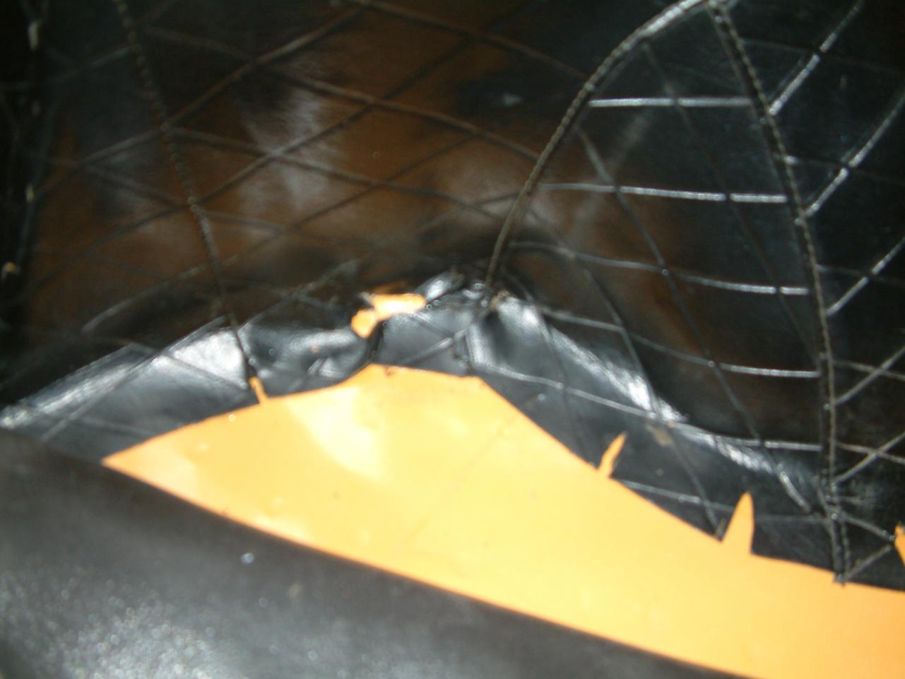
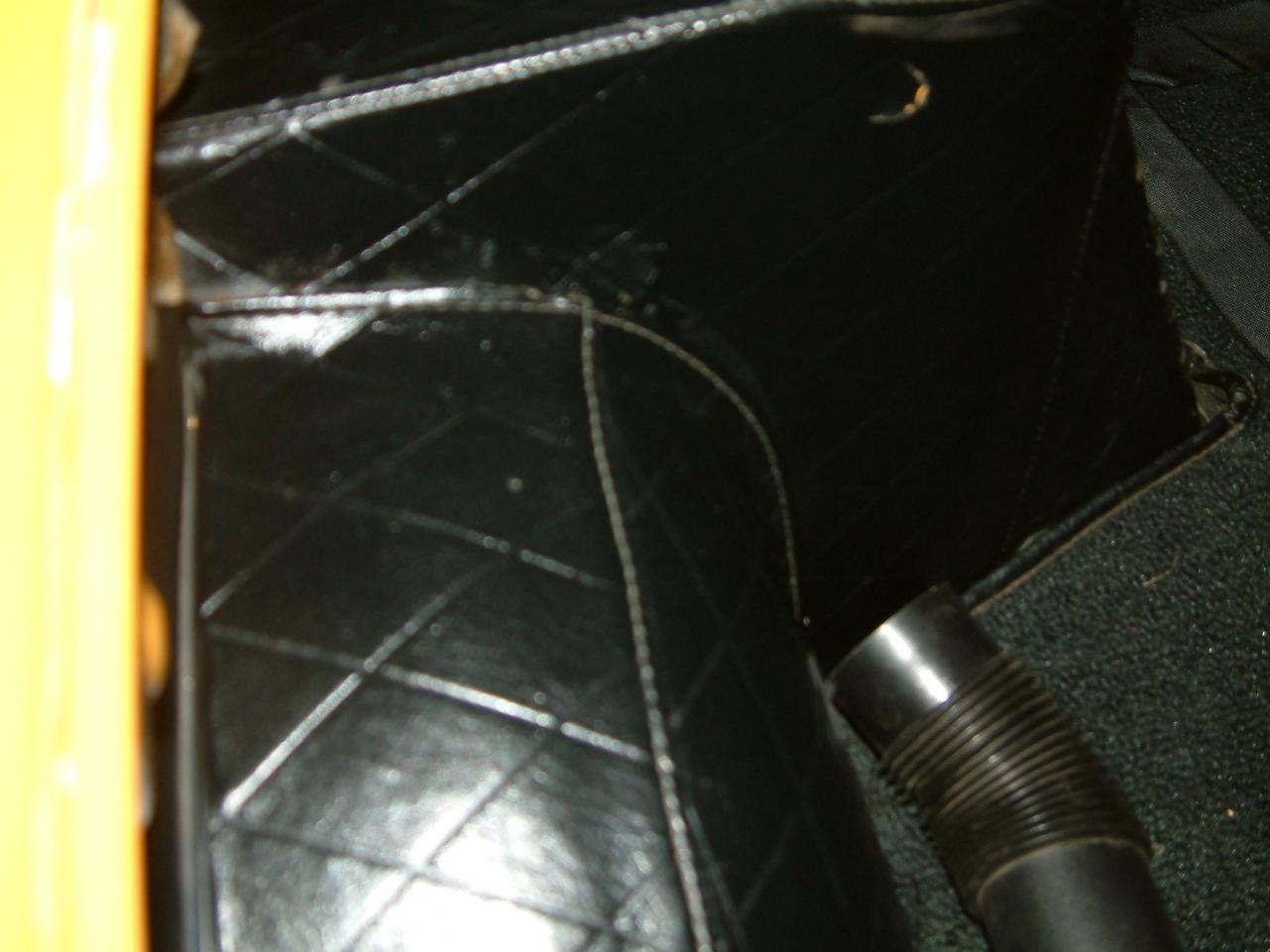
Yeah, that would fit so much better than the metal one. I searched for "evap tank" and didn't get any pictures like that. It looks like my problem will be solved in a week or so. Thanks for the picture and the offer. If the one Jim has gets lost in customs I will let you know. John:beer: