alhbln
Member
-
Joined
-
Last visited
Everything posted by alhbln
-
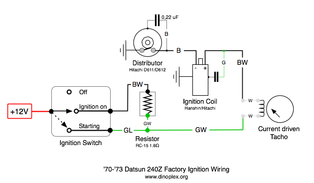
 Could be several problems, lights not working and tach pegged at 8K is clearly wrong, so i would start checking the electrical circuits, then check the advance at idle with a strobe gun and then look for vacuum leaks. From what you describe, i would second Tyler, the timing may be too advanced or retared, probably because the distributor was not set with a timing light after installation. Have added a wiring diagram of the ignition which might be helpful. Does the engine also die when you rev it without the clutch being engaged? When the engine dies, does it switch of instantly or does it die within some seconds and maybe a bit of stumbling?
-
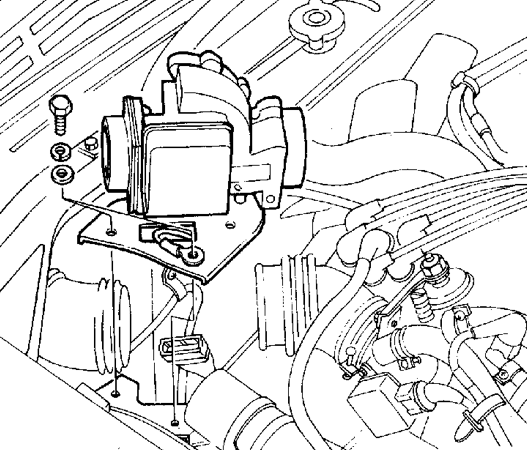
Thats the one, the AFM sits inbetween the air cleaner and the the intake manifold. (See image). When you switch on the ignition, can you measure a voltage at one of the two pins of an injector and ground? If so, then the AFM is most probably the issue, as Tyler posted. If you cannot measure a voltage, then you should check the relays next as described in the fuel injection troubleshooting guide.

-
I would suspect that the HI-6 does not get a trigger impulse from the Unilite distributor, that would explain the LED staying on (it will switch off for each trigger impulse received). You can test the HI-6 by touching ground with the white wire (points), each time you do that the LED will go off and you'll get a spark. Disconnect the Unilite distributor before doing this test. I have no experience with Unilite distributors, so can't recommend a testing procedure for checking it. (Are you Tommy? )
-
rzkas posted that he has no power at the injectors, that would be controlled by the power relay. So the problem might be before the AFM switching the fuel pump via the fuel relay. Checking the AFM is a good idea in any case.
-
Download the excellent 280-Z EFI troubleshooting guide: http://www.atlanticz.ca/zclub/techtips/efisystem/280zfuelinjectionbook.pdf Have a look at page 23-26 for a documentation of the two power relays, then apply the tests listed at 6( on page 33. The tests for the injectors power supply are on page 63-68.
-
A Flamethrower 3Ω coil should be safe. Try out the resistor in line with the Flamethrower II coil before you spend money. With the resistor in line you have a ~2Ω coil, that should be a good test to see if the tach works.
-
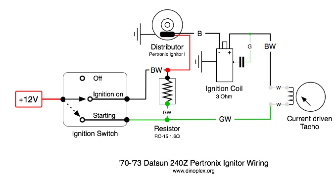
Got it, Lowell was right, you have the four wire tach type. I am still confused as this setup won't have worked without a tach adapter with the MSD, though. In your current setup, the black/white wire coming from the ignition key is directly wired to coil (+), so the tacho is not in line with the coil, which explains why it does not work. You need to wire the tacho inbetween the resistor (block) and coil (+): - The black/white wire and Pertronix red wire currently going to coil (+) must be connected to the resistor (the other side of the resistor is connected to green/white(yellow)). - The black/yellow wire should be black/white and coming from the tacho, connect this wire to coil (+). I've added a chart with the correct wiring below, hope this helps!
-
Thanks, i missed that. Its still interesting to see the result with the ballast resistor added, this mod would lower the kickback voltage send to the tach.
-
I am not sure that the HEI module can manage the 0.6Ω Flame Thrower II coil without a ballast resistor, the switching current would be quite to high for the HEI module to handle. Try introducing the ballast resistor inbetween the +12 wire and coil (+), does the tacho work then? Do you have a three or four wire tach?
-
Correct, you can remove the block and the green and yellow/white wire should be connect to the negative side of the coil. Get well soon!
-
Did you use the Pertronix to trigger the MSD or was the Pertronix Ignitor installed after you removed the MSD? My guess would be that the green/yellow (sure it is green/yellow, not green/white?) wire runs to the tach, the block is the old ballast resistor. If possible, could you take a photo of the back of your tach so we can compare the wire colors? See the post from ZCCOR#109 above describing how to remove the tach. The black/yellow wire was wired to the throttle opener vacuum control solenoid, which has probably been removed on your car. The black wire was the original connection to the distributor points contact.
-
Ignition setups can be quite frustrating at times to setup and debug, as those are the only electric circuits in a car (from the seventies at least) which depend on electric signals which change their state rapidly in a short timeframe. Anything else, including an alternator, can be relatively easy checked and maintainted just using a multimeter or even a test light, but with ignition setups you need to take care of the different signals, voltage/current levels over the time and the timing of signals itself - which is something you can't really see just using an multimeter, so this, IMHO, is the main source of frustration when trying to find a fault in such a setup. In an ideal world where you would have access to a distributor tester, scope and ideally a current clamp, finding a fault in a ignition system is quite straightforward and not that difficult if you have done it before, but most people maintaining their own car understandably don't have access to these tools. Still, with a multimeter, spark tester, a digital timing light and a bit of patience you can find most issues, thats the good news! Happy to post general testing procedures if this is of interest. Points are the simplest solution and the easiest to understand and to fix, if you are comfortable with the maintenance (setting dwell, advance weights etc). The only real limitation is the maximum primary coil current of ~4A and points floating at high RPM (typically starting at 4-5K). As Arne said, not a problem for a weekend GT. But for a high revving sports car this can be a real limitation to get maximum power and full combustion at each cycle. A badly maintained points based ignition setup with undersized wires or the wrong coil type will act as a rev limiter and lead to a sluggish throttle response when accelerating, even if your distributor advance curve is perfect. A good transistor (electronic) ignition can handle up to 8A easily, so no ignition fading at high speed and with the more advanced constant current (e.g. dwell control) electronic ignition you'll have the base for a reliable combustion at any RPM, air temperature and fuel mix (if air, fuel and timing are ok). Transistor ignitions can be driven by points or magnetic/hall/optical triggers, the later setups adds timing precision but also complexity which can make it hard to find and fix faults. The Pertronix Ignitor I conversion is quite handy as it integrates the contactless trigger and the transistor ignition in one small unit. Unfortunately, there is no current and dwell control (the type II and III is reported to have this), and depending on the coil you are using the outcome can be quite mixed. IMHO, the Ignitor I is a great unit for converting a non performance oriented car which revs up to 4-5K, but for a sports performance car (such as the 240Z) you might want to consider a different approach or use the Ignitor I as a trigger for an MSD 6A box. My personal recommendation for a six cylinder engine performance ignition setup is a conversion based on the Lumenition Optronics optical pickup driving a Bosch 0 221 100 137 electronic ignition, this combination has no fading up to 9K RPM and is quite robust. I have installed this setup in quite a lot of cars over the last years, and none failed yet. As the parts are made in Europe they might be difficult to source in the US though. IMHO, electronic ignitions are more complicated but quite worth the effort.
-
Another inconsistency (error?) in all 240Z diagrams seems to be the tach wiring. Starting from late '72, the four wire (current driven) tacho was replaced against the newer three wire (kickback driven) tach, but all 240Z diagrams i have seen just show the four wire tach. Has anyone seen a 240Z diagram actually depictig the three wire tach?
-
Hmm, i got 38º from 800 RPM up to 4000 RPM on the distributor tester. The dwell angle should not change for different RPMs, just the dwell time, at least for points based and simple transistor ignition systems. I wonder if the dwell angle variation you guys have seen with different RPMs would indicate a worn distributor or if the Pertronix Ignitor is somewhat voltage/current sensitive.
-
Lowell, Chris has the newer 'three wire' tach in his '73 240Z, not the 'four wire' current triggered tach with the white loop we have in our '72 model. The adapter could still be mounted behind the tach, good input!
-
If the ballast resistor is broken (normally they rarely break), then your engine would start but switch off when turning the key back to 'ignition', or run quite rough. If you are sure that the stock wiring has been fully restored, the trying to recalibrate the tach would be a good next step. Added: Just another test, if you short cut the resistor by connecting a temporary wire to the two resistor terminals, does the tacho work then? Shortcutting the resistor would increase the primary current and deliver a stronger signal to the tach.
-
The tach adapter would have been connected to the spade plug on the left side of the MSD 6A and the tach input. Could you check what was wired to the spade plug?
-
In the stock points/three wire tach setup, the tach is wired to the negative terminal of the coil. You will also need to remove the tach converter, which was part of the MSD setup to drive the original three wire tach.
-
Have you changed the calibration of the tach after installing the CDI unit? The calibration trimmer (accessible through a hole between the two indicator bulbs on the back) changes the sensivity of the tach, you might want to recalibrate it for the current setup. Use a plastic trimmer screwdriver. While the engine is idling, turm the trimmer pot slowly around (clockwise) until the tach needle is stable around 800 RPM. Then check 4000 RPM, ideally with a digital RPM meter as calibration reference.
-
Correct, the distance between the magnets sets the dwell period, you can't change dwell without modifying the sleeve/magnets. The transistor in the Ignitor I setup just does the current switching, no dwell or current control is supported.
-
-
Stock setup or updated ignition or distributor/pickup? Either a tacho defect in the driver circuit or the tacho input signal. What happens after 4000 RPM, the tacho needle just stops there? Does the engine feels normal at higher RPM, or does it start to run rough? The easiest way for a diagnosis would be to try another, known to work tacho. Ideally you check out the tach trigger signal with a scope to check if the duty cycle of the square wave or the amplitude changes after 4000 RPM.
-
The tacho which was installed until late '72 (also called 'four wire tacho') is current triggered, e.g. it measures the current going to a small wire loop in the +12V feed to the coil. The current is picked up by a small internal coil and then amplified by two germanium transistors (see circuit by zcarnut above). Unfortunately, this setup will only really work with an inductive points triggered ignition setup with less than 4A primary current. With a modern transistor ignition you would need to recalibrate the tacho due to the higher primary coil charge (typically 4-8A). A CDI or EDIS setup wont work at all, as in a CDI setup there is less current but a much higher primary voltage, and EDIS uses a wasted spark setup with multiple coils. After trying out different approaches and adapters, i resorted to build my own adapter, which is triggered by the points signal to the transistor ignition or the square wave signal from a MSD, Mallory or Crane CDI and then injects a 500 mA square wave into the tachs transistor amplification. Its easier to install a modern tach but i wanted to retain the original look after installing a Megajolt mapped ignition. http://www.dinoplex.org/tachoconversion/ Best, Adrian
-
Ok, so we know that the ignition works as expected, the injectors itself are functional and get their +12V supply and the air flow meter is ok. You have measured the resistance of the sensors at the ECU connector so we know that the wiring itself is ok? Are you sure about the air temperature sensor having a 26.8 kOhm resistance (that's -22F), or did you mean 2.68 kOhm (that would be ok). Optional: i would like to make double sure that the coil kickback signal is available at pin 1 of the ECU as the symptoms sound like the ECU does not receive the trigger input. if you have a multimeter with a voltage range up to 400-600 volts, then you can measure ECU pin 1 against battery (+), while starting the multimeter should show peaks up to 400 volts. Assuming now that all sensors are ok and their resistance/signal is available at the ECUs connector as measured, it is quite likely that there is a defect in the ECU. The possible defects sorted after probability: 1. Defect of the output stage transistor. I would guess that this is the large round TO-3 package transistor mounted at the side of the ECU. What is the number/type printed on the outside of the transistor? Could you trace the injector output pins (15, 33, 32, 14, 30, 31) on the PCB to which component they lead? Are the output pins internally connected? The large output stage transistor will have a smaller (probably TO-92 package, half round black plastic) driver transistor in front. This one could also have failed but both are easy to replace. 2. Defect of the incoming signal stage for the coil kickback (pin 1). Please trace the first two or three components after pin 1, it should be a resistor, a capacitor and then a small (TO-92) signal transistor. 3. Defect of the incoming signal stage for the air flow meter pot, air and water temperature. Same procedure as for 2., but we can ignore these for now until we are sure that 1. and 2. are ok. 4. Defect of the internal injector time regulation circuit. Not so likely so we ignore this for now. If you are ok with delving into the ECUs internals, i am happy to guide you here. If not, a replacement of the ECU has a high probability to fix the issues you have encountered. Do you have a multimeter which has a "hFE" setting? This setting is for measuring the function and amplification of a transistor. You would also need a decent soldering iron with a fine tip to replace component. A scope would be quite a time saver, so if you can borrow one it will really help Let me know how you want to proceed.
-
If your thermotime switch is faulty, bridging it for continuing the tests is quite ok - just don't forget to exchange it eventually. There is no real TPS on the 280Z as it seems, you have a an AFS for the air flow (e.g. engine load), and two throttle switches (idle and full throttle). The AFS is important to check (see sensor check in my last post), you might also want to check the two throttle switches while you are at it. Good luck and looking forward to your test results