alhbln
Member
-
Joined
-
Last visited
Everything posted by alhbln
-
 Good, so the +12V supply for the CSV is ok, and the thermotime switch supplies ground when the engine is cold, correct? Just want to be sure as it sounds like you manually applied ground to the thermotime switch for testing. (In post #16 you mentioned that there is no voltage at the CSV, did you change something?) With the amount of fuel supplied by the CSV the engine should nearly be able to start, just cranking sounds like there is no spark present. Quick question, have you pressed the throttle pedal when starting, or did you just turn the starter? The fuel injectors are triggered by the ECU supplying ground to the injectors when a ignition impulse is registered at pin 1 of the ECU. The length of the opening time (ground supply) then depends on the external sensors such as the throttle switch, air & water temperature and air flow. 1. You need to make sure that the injectors get +12V to the resistor pack via relay terminal 88B. A quick check is to switch on the ignition and then manually provide ground to the ground pin of the injector coming from the ECU (pin 15, 33, 32, 14, 30, 31), you should then hear the injector clicking. 2. Next the ignition should be checked, do you get a spark when starting? Is the wire between coil terminal 1 and the ECU pin 1 ok? You should be able to measure +12V on pin 1 of the ECU if the ignition is switched on to check the coil to ecu wiring. 3. If the voltage supply in 1. is ok, and the ignition does work/ignition signal is available at pin 1 of the ECU, we then need to take a look at the sensors, as a faulty sensor can confuse the ECU enough to not activate the injectors. The most important sensor for the ECU is the air flow sensor, if the variable resistor in the air flow meter delivers wrong values, the ECU might not trigger the injectors at all. You can test the air flow meter by measuring the resistance between ECU connector pin 7 and 8, it should vary when you move the flap manually. The next important sensor is the engine temperature (water temperature in your setup). Measure the resistance of ECU connector pin 13 against ground, you should see around 2000-3000Ω at room temperature. Air temperature is the third sensor to check, the principle is the same as with the water temperature sensor, measure the resistance between ECU connector pin 6 and 27, you should also see around 2000-3000Ω.
 -
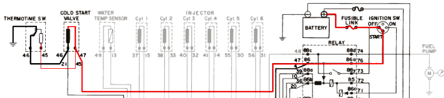
Not necessarily, the CSV is not controlled by the ECU but the thermotime switch, it just reports its state via line 4 to the ECU. There is no indicator yet that the ECU really has a fault Trace and check the wire marked red in the attachment, it connects the fuel relay pin 86 to pin 47 (original CSV connector) of the CSV. I bet this connection is broken, so you need to fix it first. If the thermotime switch itself is ok, we we might be quite close to a running engine.

-
Spend a bit of time with the fuel injection book and found some helpful information: The cold start valve is activated by the ignition key in position start, the opening time is then controlled by the thermotime switch (which acts as a variable timer based on the engine temperature) (page 17). If the engine is hot, the thermotime switch does not activate, e.g. you start with the fuel injectors only. The start signal to pin 4 of the ECU prolongs the opening time of the fuel injectors (page 15), but seems to control nothing else within the ECU So, if the input driver of pin 4 is defective, you should still have standard fuel injector activity. Question, if you start the engine with your current setup, can you measure a voltage on the two connectors of an injector? Regarding the thermotime switch, could you do a quick test: connect a wire to ground and pin 46 of the cold start valve and try to start the engine. The wire will keep the cold start valve open as long as you run the starter. If the engine now starts, your cold start valve is broken.
-
The symbol for the thermotime switch is not complete, it seems to be a temperature activated mechanical switch, not a thermistor. So, if activated (cold temperature?) it switches on the cold start valve by supplying ground and also forwards ground to pin 21. I think your guess is quite correct, pin 21 might have been assigned for checking the status of the thermotime switch by the ECU, or overriding the thermotime switch, but that feature then was never actually implemented. Based on this setup i would guess that in starting mode the ignition and fuel injectors are always active, and a cold engine then activates the cold start valve via the thermotime switch to further enrichen the air/fuel mixture. Regarding the ECU, can you trace where the conducting path after the 24KΩ resistor ends up? I would expect a small signal transistor in a TO-92 package, as 24K sounds like a line resistor to drive the base of a small PNP. Or it might drive one of the two NCC relays next to the connector, but for that setup the 24K resistance is a bit high. Thanks for the ECU photos, quite interesting! The ECU is a discrete circuit without any microcontroller help from what i can see. There are not even any TTL chips. Should be relatively easy to repair.
-
Very helpful documentation, thanks for the link. On page 24 the relay wiring for the start circuit (power relay:ignition on) proves that the starter voltage is indeed forwarded as a start signal to the ECU. The signal input at the ECU seems to be on pin 4 (see page 71), so the first test should be to measure pin 4 at the ECU against ground when starting to make sure the signal is actually present at the ECU. If its not, a quick fix might be to connect a wire to pin 86 of the relay socket to pin 4 of the ECU. There is a good chance that the ECU is not defective but the wiring is faulty. If the signal is present at pin 4 though, you might have lost the input driver stage of the ECU (ttl buffer, transistor), which should be easy to replace in most cases. p.s. could you post a photo of the internals of the ecu? i am naturally (nursely) curious.
-
I dont have experience with your specific ECU but can give some input based on work done with Marelli and Bosch ECUs which might help. A typical fuel injection ECU from the late seventies/early eighties has the following start sequence: 1. ECU listens to input signals indicating a start scenario, e.g. a low frequency pulse from the cam (engine rotation) and crank (ignition phase) sensor (in your case the cam sensor in the distributor for both rotation and phase) and (optional) a positive voltage from the start position of the ignition key. 2. ECU opens the cold start valve for delivering a rich fuel mix and opens the throttly body (typically the cold start throttle body bypass valves) to get air into the engine, then it starts firing the coil via the transistorized ignition. On some ECUs this happens for 1-2 rotations without igniton to prime the engine. Also, some ECUs activate the fuel injectors in combination with the cold starting value (or don't even have a cold start valve and only use the fuel injectors). 3. ECU fires the ignition according to the RPM signal (some ECUs limit the ignition to 10-20 rotations of the engine before stopping the ignition and fuel injection as a safety measure to not flood the engine if the engine did not start in that sequence. You then need to turn the ignition key to start again) 4. ECU listens to the RPM signal via the cam or crank sensor while supplying fuel via the cold start valve and triggering ignition impulses. If the RPM signal reaches idle speed (~600-800 RPM), the cold start valve is deactivated and the fuel injectors take over. The throttle body is opened and the throttle body bypass valves are then closed. If the RPM signal does not reach 600-800 RPM within a predefined number of rotations, fuel supply is deactivated to avoid flooding the engine. 5. Engine runs in idle, ECU manages fuel, air and injection based on RPM signals, air temperature (air density), engine temperature (water, oil), air flow etc. This is only a rough overview, as example some ECUs (Marelli IAW as example) don't have a dedicated cold start valve but enrichen the mixture via the fuel injectors by priming the engine on a cold start. I would assume that in your setup the ECU does not trigger the injection valves as the engine never reaches running RPM (see step 4), because the cold start valve does not open to deliver the air/fuel mix to enable the engine to start. The wiring done by the PO would open the cold start bypass valve while starting, so the engine has the correct air/fuel mixture, the ECU would then trigger the ignition until you reach idle RPMs (600-800 RPM), and only then the ECU would trigger the fuel injectors. Maybe the PO wired it this way because the original ECU failed to initiate the cold start valve via pin 4 & 21? If you have tried another, known to work ECU, then this would indicate that the ECU is missing another signal/sensor input to start the cold start valve. As a next step, you might want to check that the cold start valve is activated as soon as you engage the starter, by measuring the voltage on the ECUs pin 4 & 21 with a multimeter. A 12V LED (or a standard led with a 480Ω in line with one pin) connected to the cold start valve is also a good indicator. If you can't measure a voltage at pin 4 & 21 (e.g. the cold start valve is not activated), then the ECU (if it has no defect) is missing another signal input. I would recommend to then check if the starter activation wire is connected to any pin of the ECU and if that wiring is ok and the ECU receives a signal as soon as the ignition key is turned to the starting position. If there is a signal on Pin 4 & 21, then the wiring to the cold start valve is faulty (probably not the case as you have exchanged the wiring trunk loom already). I wouldnt worry too much about the ignition and the fuel injectors as long as the cold start valve is not activated while starting. good luck and let us know how you proceed, Adrian
-
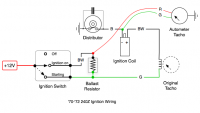
This might be a wiring problem, as the ignition does run with the tacho connected, but not while starting. I've attached a wiring scheme of the ignition circuit and added the Autometer tach, if your wiring is different you might want to try out the one in the attachment.
-
I'm a fan of structured testing to prove the theory but i guess i leave this one out, ouch!
-
3", are you sure? That would be 230KV at room temperature and sea level
-
I am currently finishing my '72 240Z Megajolt conversion, will post a report soon. As the mapping feature of the MegaJolt allows you to fine tune the advance curve in each RPM range (which would not be possible by two advance weights and some springs) on the Dyno, the engine runs much smoother and delivers more PS and torque. It is not unusual to gain up to 10% more PS and 5-10% more torque in lower RPMs by introducing a mapped ignition (they were already there, the distributor based advance curve just didnt care for them ) Checking the air flow and using slightly larger jets can further improve engine performance even with a standard cam timing.
-
Hi Christian, assuming the Pertronix Ignitor has already been installed: 1. The black wire coming from the Pertronix Ignitor goes to the white trigger cable from the Hi-6. 2. The red wire (on the same weathertight connector as the white wire) goes to the +12V coming from the ignition key. (Thats were the red wire of the Pertronix Ignitor is also connected). 3. Black (-) and orange (+) from the HI-6 are wired to the Crane coil. 4. The heavy red wire should be directly connected to the battery (+) terminal. 5. The blue wire of the Hi-6 (cylinder select) goes to ground. 6. The green wire of the Hi-6 (tacho signal) requires an electronic tacho to work, do you have a current driven (connected in line with the coil, up to late '72) or kickback driven (connected to one terminal of the coil) tacho? Have send you the Crane Hi-6 installation manual via mail. Best, Adrian
-
congrats, sounds good!
-
Failure of the green tape is one of the two main sources of defects you can have with the Pertronix setup (the other one is a defect of the power transistor, i just managed to kill one while just checking a distributor on the distributor tester, bizarre). The adjustment screw is for setting the phase correctly (triggering of the magnetic sensor in relation to the position of the distributor axle/cam position), but Pertronix never documented this.
-
Sounds like the voltage regulator. Both water and temp measure the current going through the sensor resistor and are sensitive for varying voltage levels. You might be able to see the same effect in the fuel gauge, although to a lesser extent. If its the original mechanical regulator then you should be able to hear a clicking sound from the buildin relays every time the water and temp gauge vary. Have you tried to measure the cars voltage supply yet? A cheap analog multimeter would be quite helpful as you can see the variance over time better than with a digital one. Voltage should not exceed 14.8V.
-
Your tests prove the theory There should be no difference between the 3.0Ω coil and the 1.5Ω coil + 1.5Ω resistor, as in both setups you limit the maximum current to 4 ampere (A=12V/3Ω). So, if both coils have the same winding ratio, they will create the same spark voltage and spark energy.
-
There is no real standardization of HEI modules except the size and connectors, so the current uptake might vary depending on the product. Some HEI modules feature dwell adaption and current control but most don't. The original GM modules were below 4A, whereas newer high current modules can exceed that easily. 14 AWG should be quite sufficient for most HEI modules, and the relay makes a lot of sense. I am using 13 AWG for high current Bosch 137/139 modules which charge up to 8A to the coil, works great. The inductive charge is relatively slow compared to a CDI ignition, so you don't really need a big capacitor to smooth things out (have a look with your scope, ideally with a current clamp if available). If you add a capacitor, do it as near as possible to the ignition.
-
Bosch red coil (0 221 119 030): - primary (1, 15): measured 1.8Ω, specified 1.2Ω-1.7Ω - secondary (1, 4): measured 12.9Ω, specified 7.2Ω-16.0Ω Bosch resistor (0 2278 900 001): - measured 2.0Ω, specified 1.8Ω So according to the Bosch specifications, we are both within the standards :-)
-
P.s. carbon spark cables can break and then do funny things to the ignition impulse as the gap acts as a capacitor. Would recommend going for NGK resistor spark wires as example, which use an insulated core with a thin wire wrapped around it. MSD and other brands produce the same type of spark wire using different trade names. http://www.ngksparkplugs.com/images/prod_images/display/wireset_illustration.gif
-
(Reviving an old thread) The original scope trace does indeed look like there is a second trigger, ringing would look different. What you see on the primary side of the coil is the inductive kickback of the magnetic field breaking down, in a healthy coil it should look quite identical to the secondary curve. I would suspect one of the primary transistor drivers or a charge timing capacitor being the issue, you might want to compare the input signal to the ignition and the trigger signal to the base of the power transistor using two channels of your scope. The scope picture you have posted last is missing the burn phase, also the initial HV peak does look a bit strange having a voltage breakdown right in the middle. Looks like you might have measured the ignition without a plug and engine compression. You can measure the secondary impulse by creating a simple inductive clamp using a round paper clamp (4 cm width is a good size) which is wired to the shielded wire in an RG-58 coaxial cable, the shield of the coaxial cable then goes to ground via a spring clip. Crimp a BNC barrel connector to the other side for connection to your scope. The coaxial cable should not be longer than 2 meters. 1 Volt is roughly around 10KV, depending on the paper clamps size (If you need to measure the secondary voltage and signal more precisely, a Tektronix P6015/A HV probe does the trick, if you can borrow one). If you are in a hurry, just wire some lead solder 5 times around the spark wire (with a gap of 2-3 mm between windings) some inches before the plug and connect the scopes probe clamp to one side of your homemade inductive lead solder pickup and the probes ground clip to the cars ground.
-
John, if the dizzy turns out to be the issue of the timing problems then unfortunately it is not likely that an upgrade to an Pertronix Ignitor will solve this. Going for a good 280ZX E12-80 instead sounds like a good plan. I don't know if the 280ZXs advance and vacuum curve are identical, but as this seems a common upgrade path for 240Z owners it should be ok. The 280ZX distributor uses a magnetic pickup to trigger a transistor for switching the current, this is the same principle as with the Pertronix Ignitor, and might even be cheaper than buying a new Ignitor. You might want to get the 280ZX coil too (a coil for a transistorized setup has different specs and coil ratio). Good luck, Adrian
-
Just had a look at the circuit, that would work indeed!
-
John, workbench testing of a coil requires an ignition pulse generator or a frequency generator to simulate different RPM ranges from 500 to 7000 RPM and an ignition/transistor module to trigger the coil. Not cost effective if you don't have the tools or know someone who has, borrowing a known good coil which is compatible would then be the best approach. I meant condenser, capacitor is the technical term for the component, sorry for the confusion. You can build your own spark tester with a plastic ruler, some tape and two screws to set the distance but take care not to get zapped. One screw goes to the output of the spark wire end normally connected to the plug, the other screw goes to ground. A distributor tester is a specialized motorized tool to measure dwell, timing and variations at all speeds. A workshop handling cars build before the eighties should have one, a test of your distributor might cost anything between just a tip and $50. The dwell angle does not change with RPM, but the dwell time (how long the points open before they close) does. The dwell angle is based on the shape of the cam and the gap of the points itself, so it remains constant at any speed. The most cost effective approach after testing the coil would be to borrow a know good and compatible distributor and then decide if you have your original one rebuild or buy a rebuild/new one if the borrowed one fixes the symptoms. If the borrowed one does not fix the timing symptoms (which is IMHO somewhat unlikely given the tests you already did) you need to check the engines distributor drive gear or issues with the timing chain. It seems that you have both a problem with the ignition electrics as the spark is weak (it should not, if dwell is set correctly and the supply voltage/wires/points/coil/spark wires/plugs are ok) and a timing problem. I would assume that the timing problem is most probably due to a worn distributor. Best, Adrian
-
Correct, but with a four wire tacho setup ('72 and pre) you would lose the tach output, as the black wire also runs through the induction pickup of the tach. 0,7V is not so bad as a loss, though.
-
The three wire tach measures the inductive kickback from the coil, which is around 100-200 volts, so a different resistor on the primary side should be no problem at all. The resistor is required to limit the current going to the coil for creating the magnetic field. Depending on the coils primary wiring and resistance, an external resistor might be required to limit the current. Some coils (such as the Bosch blue coil) already contain the resistor as part of the coil circuit. In a classic points setup, the resistor is bridged while starting, to still get the full voltage at the coil even when the starter is engaged. As soon as the starter is disengaged and the voltage supply is stable again, the coil is fed via the resistor. A typical coil in a points setup has a maximum primary current of 2-4 Ampere. A higher current will saturate the coils windings, the additional current is then just turned into heat (overheating the coil in the mid to long run). The job of the resistor is to keep the current just below the saturation. As a rule of thumb, if a coil is too hot to touch (e.g. >70C/150F), you are running too much current through the coil. The condenser increases the lifespan of the points by eliminating the high voltage of the coil primary kickback, which would otherwise create a discharge arc between the points when the points open, quickly eroding the points contacts. In a transistorized setup such as with the Pertronix Ignitor, you do not need a condenser as there are no points to protect anymore.
-
jwgarey, the symptoms you describe sound like either a defective ignition (in your setup the coil is the only thing left not yet fully tested on a workbench with different RPMs while measuring primary current and secondary voltage. Measuring the primary/secondary resistance with a multimeter only diagnoses broken wires or severe shorts due to wire isolation issues in the winding, but does not show issues with the inductivity or thermal issues) or timing/phase irregularities induced by the distributor. With a good distributor, in general the timing should not wander more than 1-2 degrees while idling. 3-5 degrees are a lot and point to a worn out distributor/distributor drive. A worn out chain could create similar effects. If the issues are only apparent on specific plugs (you last posted that this is not the case), the distributor, spark cables and plugs need to be checked. The most common issue here is a defect in one of the spark wires, cap issues, or a partially worn down or dirty cam. If your issues are random (spread to all plugs), the full ignition setup must be checked, with a focus on the points, capacitor, coil, ground connection and voltage supply to the ignition. Assuming that air and fuel have been checked and are fully functional, you might want to do the following checks to ensure the ignition components are ok: 1. Measure the resistance from the batteries negative terminal to the engine block to ensure the ground connection is good. The resistance should be not higher than 0,5 ohm. 2. Use a simple variable spark tester to test the available spark energy at the end of each spark cable going to the plugs. The spark should be strong enough to at least jump a gap of 1 cm/0.4 inch. A healthy ignition can manage 1,5 cm/0.6 inch, a CDI such as the Mallory Hyfire or MSD 6A easily does 2 cm/0.8 inch. (example: http://www.thetoolwarehouse.net/p-3156-lisle-50850.aspx) 3. Remove the distributor and do a thorough run on a distributor tester. Even if the distributor axle seems to have no play, a combination of a worn out drive, axle and cam can create critical timing and phase errors. A worn cam can create irregularities in the dwell, ignition timing and phase errors. 4. Test the running engine with a motor tester (ignition oscilloscope, as build by Sun, Bosch, Pico and others) and compare the spark discharge pattern by each cylinder to check for timing and phase errors and correct ignition and burn phase. If used by an experienced person (your local workshop might help), using a motor tester with an oscilloscope is the quickest and easiest way to diagnose ignition and timing problems. I would recommend leaving the vacuum disconnected for testing, add this later on if the core issues have been fixed. Vacuum advance is only relevant for more economic fuel usage in idle (no load condition). Close the vacuum tube coming from the engine while testing without vacuum. As a first quick test, you might want to change the coil against a new one (Bosch red coil with a resistor should be fine for your setup). Check the engine/ground resistance as in step 1 first. You might also want to change the plugs against a set of new ones to be sure. NGK BPR6EIX are a very good choice for the stock points and coil ignition. Let us know how you get on. Good luck, Adrian