Mikes Z car
Member
-
Joined
-
Last visited
Everything posted by Mikes Z car
-
 EuroDat, Your lens looks really great! I'd be proud of that work. Mike
 -
I hadn't thought of the effect of the logging road on... Imagine ripping that gorilla tape off. Arrrgghh...
-
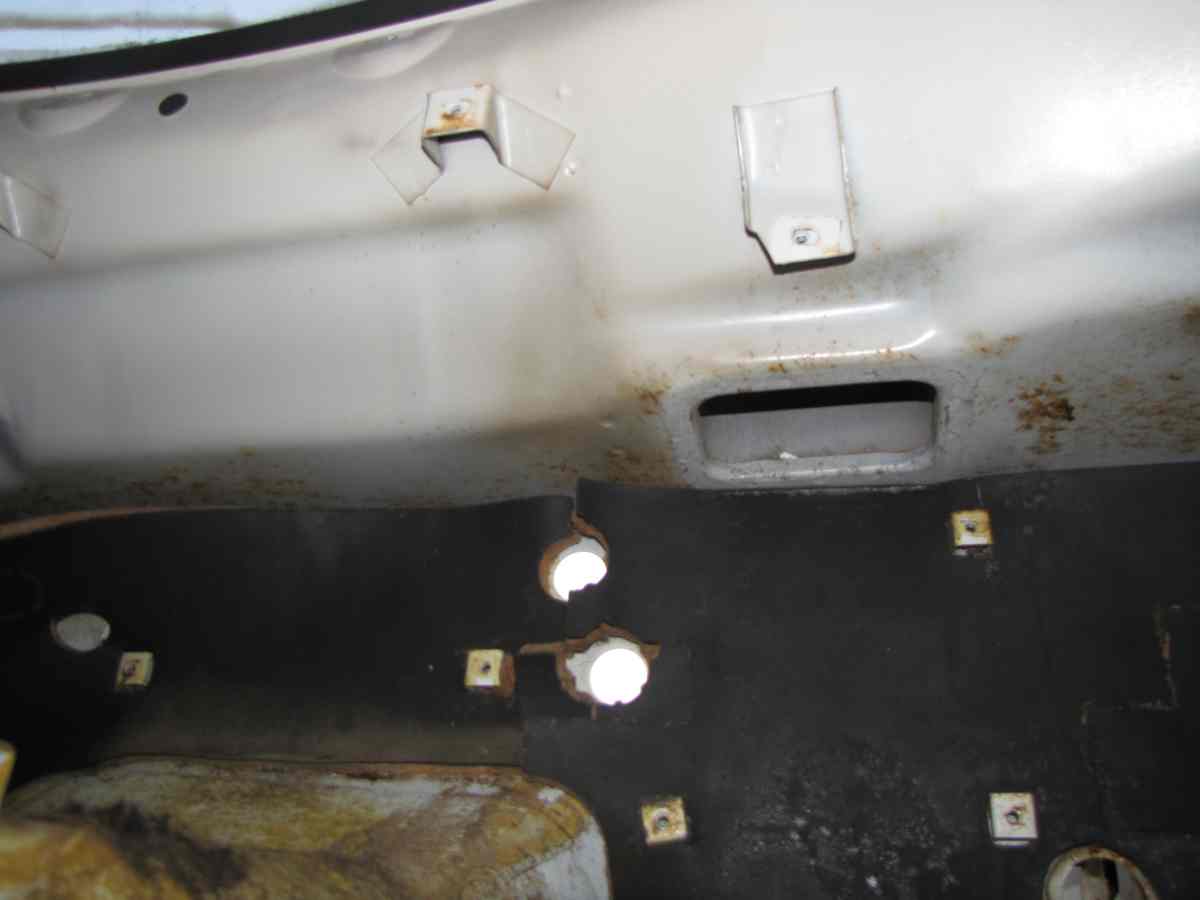
Here are pictures of the firewall insulation of a 1/1972 240Z on a "fabric board" with lines 1 inch apart going both ways to allow duplication if for some reason someone wanted to. Note that the top edge of all three pieces of the insulation are lined up with a blue line on the fabric board. Pictures were taken in full sun and have shadows. To clarify where the black insulation poster board ends and the shadow begins white dashed lines have been drawn. This could be printed out and the blue fabric board lines drawn as white lines with a ruler to extend what is on the fabric board across the black insulation to make duplication easier. Or start with a fabric board (cheap, can get in fabric shops) drawing what you see here on the cardboard fabric board as a pattern. The insulation pieces are from a 1972 January MFR date 240Z they didn't come from the car shown in my signature. Driver's firewall insulation: Passenger's firewall insulation: In car- driver and middle sections: In car- passenger side:
-
Yes the no hair getting in the way was considerate. A better road would have been an old logging road with plenty of ruts but that might have been hard on the Z.
-
Oh okay I understand now. If you do some experimenting with this if you are so inclined I would be curious as to how any of this might turn out. They make a mould release, I don't know if it would be any better than vaseline.
-
As info, Bill Reagan has once again dropped the price of #201, to $3900. His ad is in classiczars.com in the classifieds. I tried to put a link here but the URL kept showing the old price for some reason.
-
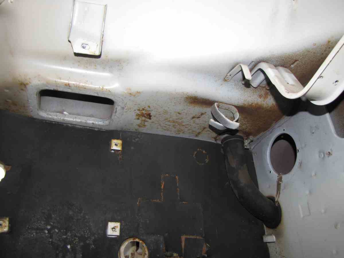
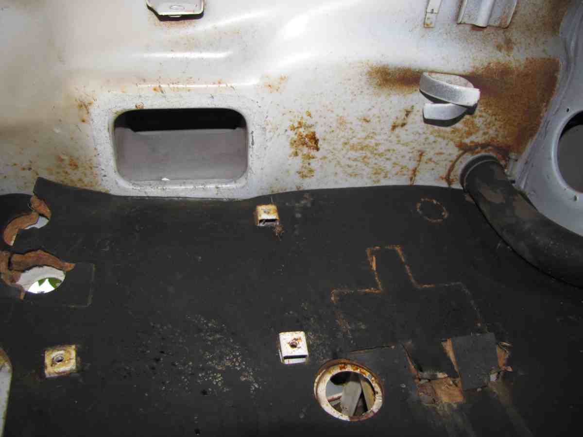
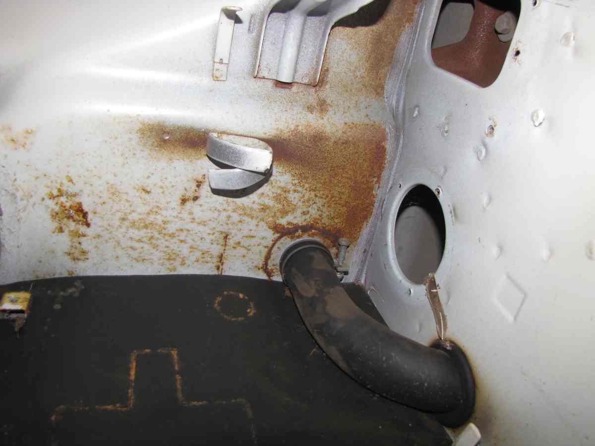
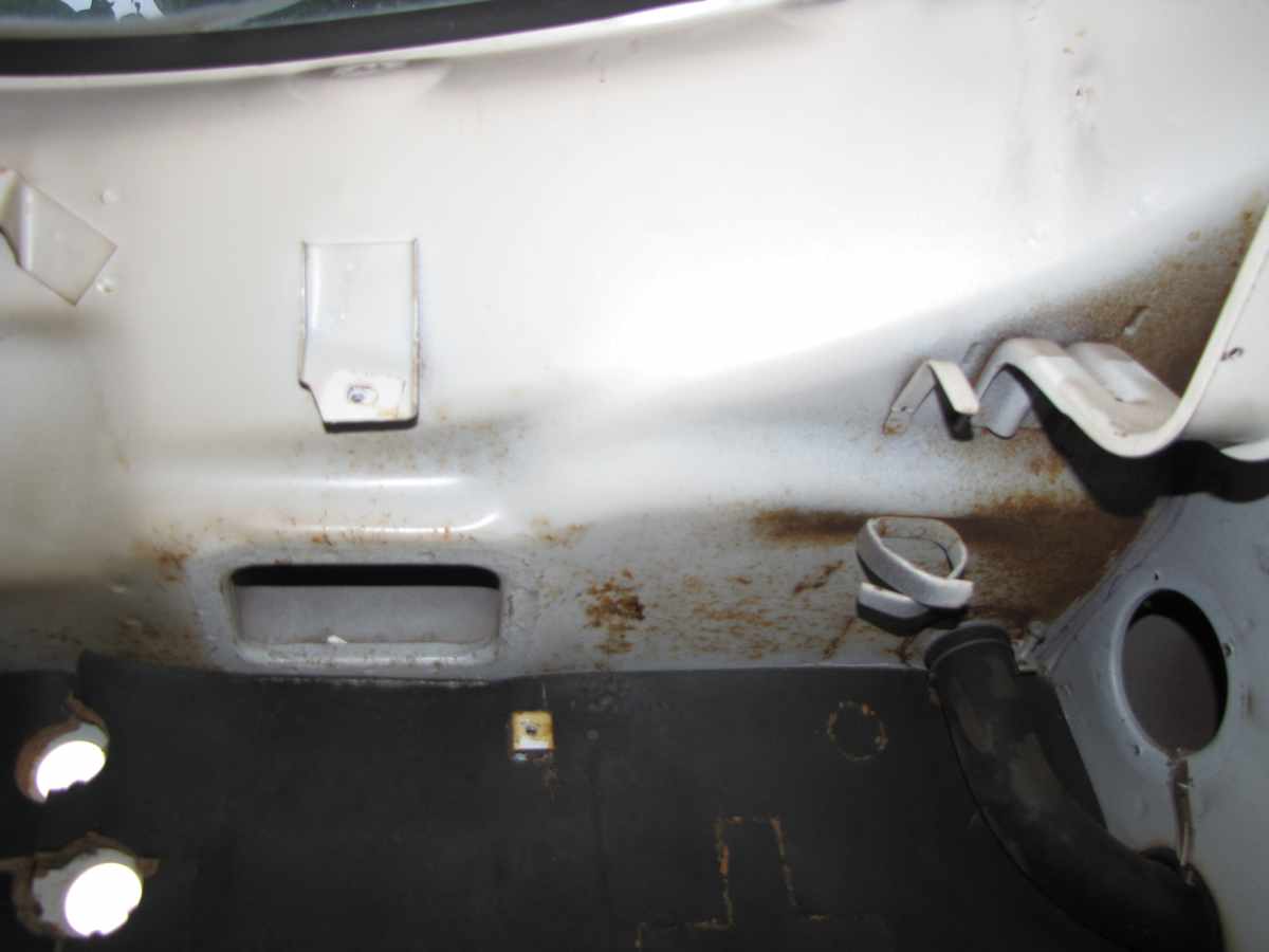
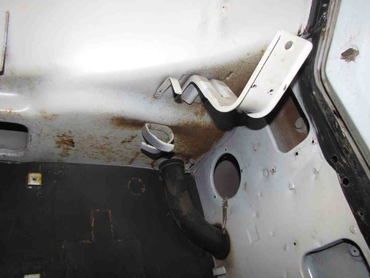
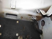
Here are some pictures behind the glove box but the firewall insulator is still there. It might be better for you if I get back further from the firewall (the seat was in the way but it is not bolted down) to include more area in the pictures for better reference. I am willing to pull the firewall insulation off and take more pictures, want to be sure it is easy and isn't thoroughly glued.

-
Is that paint, er...
-
Hah! That is pretty neat. For some reason I get excited about figuring out how to make parts from moulds or other techniques for making parts. I have some mould rubber for making moulds that I haven't used yet. I want to eventually try to duplicate the badge in the middle of the horn button just to see how it might come out. First though, I have to get a horn button to duplicate. I wasn't sure what you meant by pressing other parts into the same mould. Did you mean the first mould can spawn another mould for a different part that has some commonality as far as its shape as compared with the first part?
-
I cut one of out of an old truck inner tube for one I have but recently I noticed in another one that there seemed to be two gaskets, besides the rubber one there seemed to be a brown possibly translucent gasket that was very thin compared to the rubber one and seemed like it was made out of plastic. But for fun how would you use plaster of paris to make one?
-
Sorry, I misunderstood. From my experience using the Ace Home and Garden type sprayer for spraying trees I imagine it will spray phosphoric acid quite a ways inside a rail, maybe a couple of feet past the tip of the sprayer.
-
Blue, I have one of those sprayers to use on my z car for possible anti corrosion work, but would it double for a cheapskate paint job? I wonder if you could put thinned sherwin williams house paint in that. Bruce, I also am amazed at the resourcefulness of car guys. I wonder what pointers if any the Cuban dudes who don't have replacement parts could give? Lawn mower carbs on a Z car? The Transtar Amber spray material for anti corrosion I understand has a limited shelf life too. I did use one can after a year and it still sprayed though I don't know how the age might have altered the effectiveness. It looked okay. Right after using it I always soak the 3 foot long tubing in hot soapy water and force water through it though maybe paint thinner or some other solvent would work better. I seem to kink the tubing making it hard to use before any clogging issue, haven't clogged it yet but I don't know for sure if the hot soapy water is helping much.
-
Blue, I was wondering if dirt in the four butterfly shaft bearings as they go through both sides of both carbs would cause friction that would cause the jerk? Maybe spraying the bearings with carb cleaner would help? I haven't seen a clear picture of what the butterfly bumps into at its top and bottom when it is closed. Maybe wear on the shaft bearings would let the butterfly contact the carb wall in a way it didn't when it was new?
-
Well if you want the fire wall area and the area above that which is normally behind and above the glove box meaning you are drawing a left hand drive car I have 1972 parts car I have the dash out of I will take pictures of much later today though someone else may be able to provide better pictures than me and before I can get to it.
-
I am curious about how well the SK carb does with the cold start circuit in cold weather? Anyone know how it works? granny, I always enjoy seeing Ted your cat, I like cats and he looks like a good one.
-
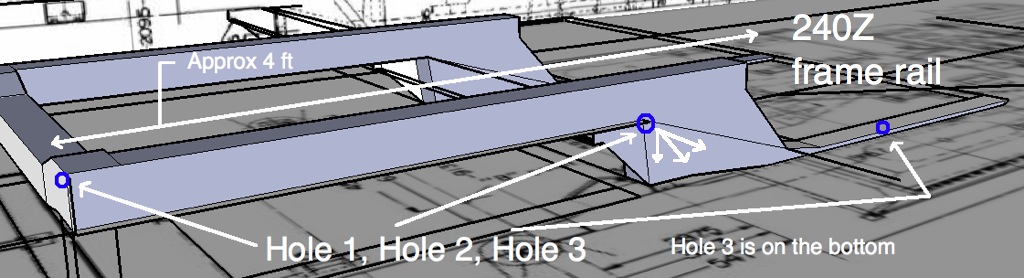
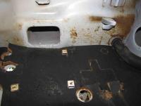
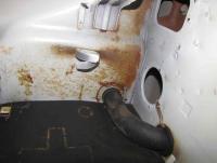
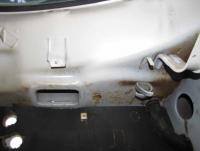
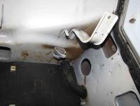
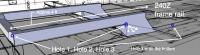
This thread describes what I did: http://www.classiczcars.com/forums/body-paint-s30/40048-two-frame-rails-tc-rod-there-floor-between-them.html Holes I enlarged or existing holes I used to spray anti rust: I also made twin holes 2 inches DIA, one under the gas pedal to get to the rear end of the driver's frame rail closest to the driver and a similar one under the forward foot area of the passenger floor to get to the inside of the passenger side frame rail. I used a Transtar Amber spray can as the nozzle for it (purchased separately) has a 360 degree spray pattern. The Eastwood spray can that Blue points out sprays radially which sounds like a similar pattern.
-
Another one (mentions a cable that does not require grinding off anything on Datsun gas pedal): Throttle cable setup - Lockar & custom bracket - Drivetrain - HybridZ
-
z boy mn. I only have cable on my daily driver which is an old '83 Toyota SR5 wagon though I am also curious about using cable on a Z if anyone has pictures of their setup. For Blue, I'd love to see how linkage modeling might be done with excel. I saw some two dimensional (in a flat plane) linkage modeling using a microsoft office product (might have been excel or powerpoint) a year ago somewhere on the net but couldn't see how to make it work for a Z multiple link setup. It might be possible to do 3D dynamic linkage modeling in sketchup, but is the output desired a graph showing gas pedal linear mm input movement VS rotational degrees of butterfly shaft movement? A goal might be your eccentric idea with a slow take off that gets faster at mid pedal depression and then tapers off at maximum gas pedal depression? I don't know what might be ideal for street driving other than slow or linear butterfly movement as the pedal is pushed off of idle.
-
Thanks beermanpete, Since the PO upgraded my car to a 60A alternator it gives more reason to upgrade those connectors.
-
Blue, I just figured if we could get you dragged into this discussion we would get another valuable point of view. heh heh
-
I notice my DD uses a cable that feeds to a round "pulley" on the butterfly shaft so the mechanical advantage is very close to the same throughout gas pedal depression meaning the rate of rotation of the butterfly shaft is linear. Pedal action is very smooth and the car uses a carburetor. I don't know if linear action matters for racing. Does vacuum pull on the butterfly to make it stick? Maybe unhooking the return springs and the linkage to the pedal when the car is running would answer that. Maybe compare that linkage friction to the friction when it is not running. Just ideas.
-
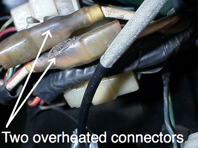
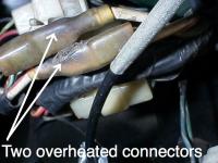
I noticed these two overheated connectors to the right of the glove box (above passenger's right knee in the U.S.) on my 240z when I got it: To fix them I soldered the four crimped connections between the wires and the two connectors to eliminate further overheating. I also slightly squeezed the gripping side edges of the two female connectors to grip harder on the connection and sprayed the connectors with deoxit, following up with dielectric grease. I understand that one of these two white wires goes to the battery and the other one goes to the alternator and between them they carry all of the current that goes through the fuse box. I have three questions: 1. Are there other ways to fix these two overheating wires such as bypassing the connectors by soldering (or crimping) the wires together to get rid of the two connectors entirely? 2. Is there any impact from having these connections overheat such as does increased resistance and voltage drop affect battery state of charge? Could impact take the form of dim lights or fluctuating gauges? 3. Or is the battery voltage sensed at the battery by a separate wire so the voltage regulator accurately sees the battery voltage allowing the alternator to accurately charge? I notice my parts car shows overheating at these same two connectors. Thanks for any ideas. Mike
-
The PO for my car bent the arm on the linkage to help with throttle jerk but it doesn't get rid of the prblem completely. I sure remember my other 240Z from 30 years ago taking off fast from every start. A passenger mentioned it to me once. (Is that why you like these little cars?) More info here: Throttle jerk fix - Blogs - Classic Zcar Club
-
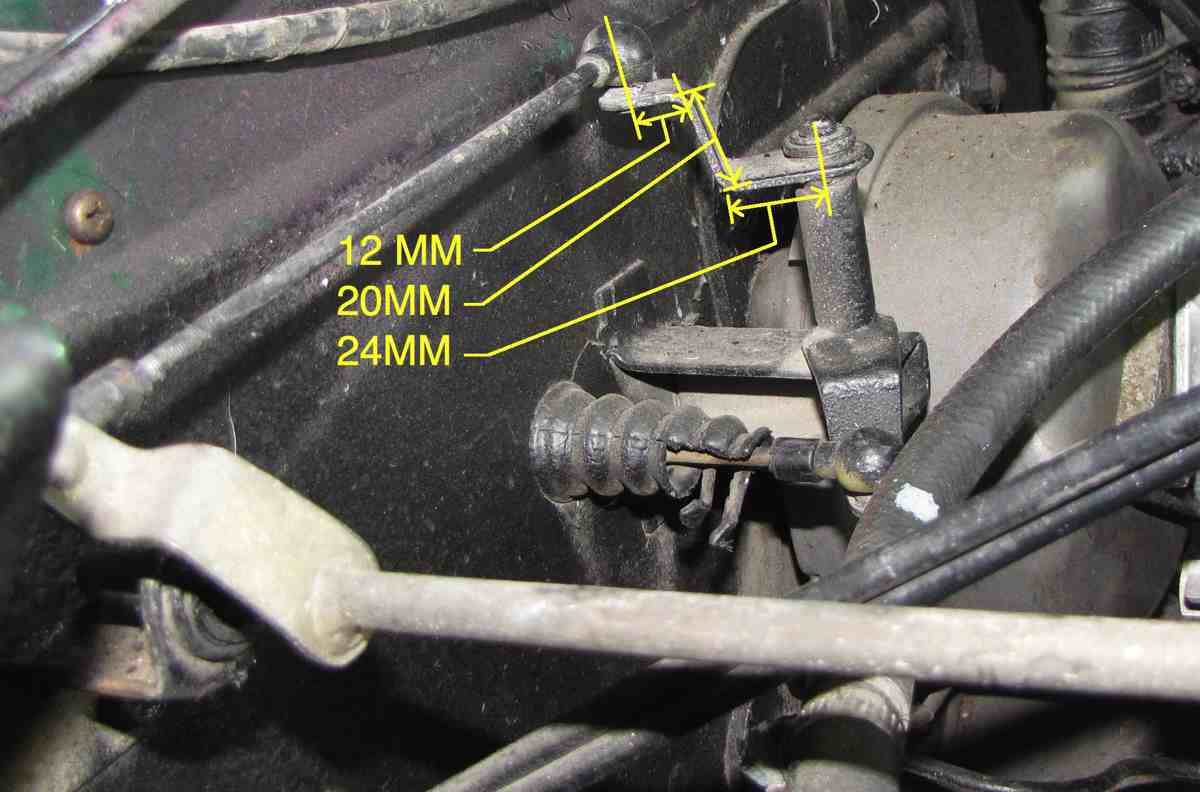
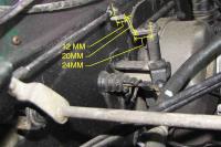
Hi all, This mod eliminates MOST of the throttle jerk but not ALL of it. I owned the car for 4 years before I noticed it still has a small amount of throttle jerk. The previous owner of my 240Z reduced throttle jerk from idle to take off by bending the upper arm of the "turnstyle" as seen in the attached pictures to a stair step shape effectively shortening it. This mod is no cost, possibly reversible and requires no welding, drilling or adding parts. The connecting rod with a nylon ball on both ends connecting between the turnstyle and the carb control shaft arm may not need adjusting or modifying as the new turnstyle connecting point for the nylon ball is both closer in one plane and further away in another which appear to cancel each other out. The PO for my car did this mod however the connecting rod on my car does not appear to have been modified. The first picture shows measurements of the bend in the upper turnstyle arm. The measurements on the ends of the arm are from the center of the pivot to the first bend and from the other end it is from the center of the nylon ball to the first bend from that end. This mod eases the throttle jerk by reducing "mechanical advantage". The carb butterfly opening is slower as the gas pedal is first depressed off idle compared to the stock arrangement. To the PO who did this throttle fix a tip of the hat and a moment of silence as I am aware he has passed on. Mike Measurements: Side view: Overhead view:
-
You got me thinking TomoHawk about restoring old car capacitors by drilling out the guts (sounds drastic doesn't it?) of the old capacitor and replacing the insides with a new radial lead capacitor (connecting wires stick out of both ends of a cylinder shape) as people who restore old radios sometimes do to maintain original look. You would have to drill a small hole in the sealed off end of the metal can to get the wire on the ground end of the capacitor to feed through or possibly use an existing hole after clearing the hole of any solder if there is any. If drilling, the hole would need to be drilled on a side not normally viewable for originality appearance. That ground wire would have to be soldered to the metal can. I THINK I remember seeing a soldered point on one of those cans where the ground wire is soldered. Using the existing soldered area if there is one would make soldering a new capacitor in much easier. The can would have to be wire wheeled or otherwise made very clean for the solder to stick. I think the can is steel which I believe will solder but not as easily as copper. Not everyone would want to solder the wire though a small spade lug could be crimped on both ends I imagine with some loss of originality on the ground end. The can and the new crimped on wire could both go under the original mounting screw. The open end could be packed with (black?) silicone or anything that wouldn't melt easily. The wire coming out the open end might need insulation (what they call spaghetti insulation, looks like small heat shrink tubing) Anyone interested in writing an article on this? Maybe a new thread on this would be in order.