Mikes Z car
Member
-
Joined
-
Last visited
Everything posted by Mikes Z car
-
 JLPurcell, Yes you could build a regulator, the Shack sells an adjustable voltage regulator that would be suitable for dropping 12V down to 1.5V. The package has the schematic for wiring it however (edited later) the LM317T they sell as their part number 276-1778 has a minimum load requirement which the Shack schematic does not address. To make this regulator work with a minimal load like a quartz clock, add a 320 ohm resistor across the output. The LM317T part number would be recognized by Digi-Key, Mouser (I see it on eBay now) or similar electronics supply. I thought I might want to do as you suggest so I extended the wires from the existing 12 V power for the 240Z clock down to the AA battery holder that will go next to the fuse box in case I want to connect a voltage regulator later and get rid of the AA battery. I like the idea of keeping vendors for the Z happy, they are important. Mike There are two resistors shown on the Shack schematic, 240 ohms connects between the adj and Vout leads and a 5K variable between the left (adj) lead and ground to set the voltage output. The input lead of the LM317T connects to a 12 volt source that is always on such as the 12 volt source for the original clock, the ground lead would go to any ground on the car and the output would connect to the +battery connection for the quartz clock after the variable resistor was adjusted for 1.5 volts output. The -battery lead of the quartz clock would go to any car ground. The 320 ohm minimum load resistor not shown on the Shack schematic but required goes from the + battery connection to the - battery connection on the quartz clock. This regulator will fit inside the clock case as the quartz clock does not take up as much room as the original mechanical movement however it might be better to mount it outside the case to avoid blocking light from the instrument bulb. If the regulator is mounted inside the metal clock case it needs to be insulated from the clock case and would need to be glued to the case to prevent it from brushing against the time set knob on the back of the quartz movement which could cause the clock to stop.
 -
Hi all, I got a quartz clock from Michael's (arts and craft store in USA) and replaced the mechanical clock mechanism in my 1970 240Z (my clock face says JECO). There is a thread where someone else used this same clock for their Z, the following is my experience. The easiest way to do this IMO is to use the hands from the new clock and to wrap wires onto the new clock battery connections to remote the battery location to perhaps the fuse box. I didn't install that way as I wanted the clock hands to look stock and I prefer soldered connections. Materials needed: A Quartz clock from Michael's ($18), see pictures of clock card for model B Battery holder for AA (or AAA) battery from Radio Shack C Small wire to run from clock to battery holder D Epoxy glue E Glue gun to put a dab of glue on inside of set time knob F Optional tape to cover three bolt holes in back to keep light in G Bench grinder, dremel or possibly sand paper (to remove raised edges on back of clock face and hour hand) H Soldering gun if soldering connections 1. I ran the new clock for 24 hours verifying accuracy. Michael's clock front bezel and final result: Bezel (not used):___Final result: Clock card from Michael's: The existing clock can be taken out through the heater fascia panel or glove box. Thread on removal: http://www.classiczcars.com/forums/help-me/46462-new-clock.html?highlight=liner Also see clock threads listed below. I went through the heater panel as it was already open for other work. Per these clock threads some 240Z clocks have a bracket for mounting, mine doesn't seem to have a bracket. My clock was held on with an 8MM bolt that is also a phillips head. I had to use a nut driver for more leverage. 2. On back of the clock I removed the three small nuts. I also removed the 2 screws that hold the two clock halves together. I cut the wires for the motor off the back of the clock. 3. I pulled off the Z clock hands but had to gently use a small screwdriver from the side to persuade them to come off. Screwdrivers can be covered with tape to prevent scratches. Inadvertent scratches can be marked out with a black marks a lot. 4. I covered the 240Z clock face with a ziploc bag I cut a slit in to go around the center hole by taping it on both sides of the thin aluminum face to protect it though thin cardboard might have been better protection however I didn't damage anything. I did not tape directly to the front of the clock face to avoid marks. After removing the hour hand from the 240Z clock to prepare it for re-use I taped the front of it to a piece of cardboard to expose the raised edge to discourage it from taking off while using the bench grinder on it. I ground the raised edge flush on the back of the face and the back of the hour hand. The minute hand didn't need modification. Front view:............................Raised edges on back to be ground off: 5. I epoxied the new clock movement around its edges onto the back of the face making sure to get the post for the hands centered in the hole on the face. Epoxy wanted to let the new movement slide out of position so I re-centered it a few times as it dried. 6. I wanted to re-use the 240Z hands but they have mounting holes that are too big to fit tightly on the new movement so I epoxied the 240Z clock hands on top of the hands on the new movement from Michael's. To make that possible I cut off about 1/4 inch of the minute hand on the new movement as it was too long and would have been been seen sticking out from under the end of the stock 240Z minute hand. On both hands on the new movement I ground off part of the sides of the arrow on the ends of the hands as they were wider than the width of the 240Z hands and again would have been visible once the clock was placed into operation. I had to be careful here as the new hands are thin aluminum. 7. For the battery connection I could have wrapped wires onto the existing battery holder which would have been much easier than what I did. An idea here would be to wedge the wires in the battery compartment with a wooden dowel cut to the size of an AAA battery and maybe glued in. Another idea might be to solder the wires to a small piece of flat copper with the flat copper wedged in between the battery connections and the wooden dowel. See * below for how I did the connection to the circuit board. 8. I pressed on the hour hand from the new movement that had been prepared to be physically smaller so it would hide under the 240Z hour hand. Next I epoxied the 240Z hour hand that had had the raised edge removed on top of it. The edge would have raised the hour hand to a height to where it would not have cleared the minute hand I was about to install. The 240Z hour hand wanted to slide off center so I had to recheck it periodically as the glue dried. Five minute epoxy might have worked better. 9. To install the minute hand from the new movement I put it over the already glued on hour hand to check for clearance, I needed to bend the minute hand up and over the hour hand assembly using tweezers for the bending. I applied epoxy to the 240Z minute hand with a toothpick to make sure I didn't get too much that might flow into the second hand mount point (not used) in the center of the new clock post to avoid having it bind. After gluing the stock 240Z minute hand I had to recheck it periodically as the epoxy was setting to check for centering and to make sure it was sitting flat with respect to the face. I put a toothpick across and on top of the minute hand at the post it was on with a small weight on the toothpick with a spoon to hold up one end of the toothpick with the idea of keeping the minute hand flat and centered on the post so it would look right. 10. For the time setting function I put a small dab of glue gun glue on the end of the set knob next to the minute hand (a thread mentions using a glue gun). This was to make the set knob reach further when pushed in to contact the 240Z minute hand that was glued on top of the new movement minute hand. I made sure to get the glue down in the slot at the end of the setting knob to secure the glue better. Too much glue can be trimmed with an ordinary finger nail clipper. I think the end of the glue dab needs to be fairly flat. Not enough glue and the set knob when pushed in won't contact the minute hand making setting the time impossible, too much glue and the knob will bind the minute hand possibly stopping operation of the clock. One other thing I did to further secure the glue dab was to take a toothpick and apply a very tiny amount of epoxy to the junction between the dab and the set knob. I used jeweler's magnifying glasses to make sure I didn't glue the set knob so it wouldn't push in. 11. The end result is that the clock looks great installed in the car and is keeping good time. Here are threads on fixing Z clocks: Zclocks good quality: http://www.classiczcars.com/forums/thread5093.html Keep hands from new clock: http://www.classiczcars.com/forums/open-zcar-discussion/48910-clock-redo.html Getting clock out thru glove box (tends to destroy glove box) or heater panel: http://www.classiczcars.com/forums/thread9492.html Different kinds of clocks described-motor type-pendulum type: http://www.classiczcars.com/forums/thread18442.html Fixing electric circuit type clocks: http://www.classiczcars.com/forums/thread22795.html Replace with desktop auto car parts store clock -orange face: http://www.classiczcars.com/forums/thread36393.html Replacing capacitors on clocks that use them sometimes helps: http://www.classiczcars.com/forums/thread18851.html Zclocks and Auto Meter clocks discussed: http://www.classiczcars.com/forums/thread13723.html Clock runs when car runs but then quits a few days after car is parked: http://www.classiczcars.com/forums/thread12992.html Changing out mechanical movement to quartz discussed, radio shack 12 volt to 1.5 volt regulator mentioned: http://www.classiczcars.com/forums/thread10767.html Oiling original mechanical clock sometimes works sometimes doesn't: http://www.classiczcars.com/forums/thread7817.html * I tried to solder to the connections in the battery holder but the solder would not stick. To solder directly to the circuit board I took the movement apart by unscrewing a screw and unsnapping the two plastic latches on the sides. I soldered the new battery wires directly to the circuit board where the existing battery holder connects VIA a spring like action by two prongs (The prongs aren't soldered). I scraped off the two circuit board "pads" with a pocket knife where the two springlike prongs connected and got down to a copper colored metal which my solder gun could solder to. The wires I used are very small 30 gauge, they need to be to make for easy soldering to the small pads and to make it easy to get them to pass out of the movement though a small hole could be drilled in the plastic case of the movement for the wires. I personally feel taking the movement apart and getting it back together properly was not particularly easy as there were several very small plastic gears that kept falling off and I had to remember where they went. Clock innards: 12. **** How to get rid of the AA battery: **** Schematics below include the 320 ohm resistor needed for quartz clock per spec sheet for minimum load of 4 mA. Be sure to adjust the 5K pot for 1.5V out before connecting clock.
-
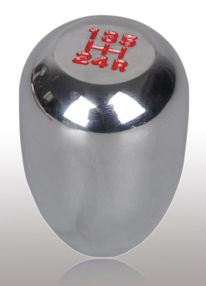
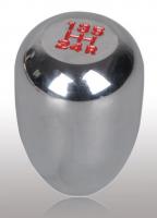
Captain Obvious that looks terrific! What did you use to make the insert out of? Geezer, this should be the shift knob you mentioned:
-
BE SURE TO SAVE THE FOLLOWING ZIP FILE PICTURE FOR PRINTING NOT THE ONE VISIBLE ON THE SCREEN (keeps DPI correct to print to original size): clock face 240Z series 1 scan cleaned.jpg.zip For viewing but not for printing: The attached .ZIP file clock face is a scan of a 240Z series 1 clock. The original clock face was removed from the clock and placed on a scanner so there should be no perspective distortion. It could be printed out for a creative project if someone were so inclined and placed on a desk top clock face (might need white hands?) to make the clock look like a 240Z series 1 clock. To do this you could pull the hands off or possibly point all the hands in the same direction and feed the printed face over the desk top clock hands through a hole cut in the middle if one of the hands doesn't stick out in both directions from the post for the hands. Another option is to use a razor blade to cut a slit from the middle to one edge and make a small hole in the middle for the post the desk top clock hands are on. Usually it will look better if printed on photo paper. To print this the same size as the original clock face select 100% scale in print preview and don't change the resolution from the 600 DPI the .ZIP file image is currently set to. Note that the scan here includes the four curved slots that allowed light through from inside the clock for the night time light for the clock, these curved slots would not normally be seen when the clock is installed in the vehicle and may be cut off. To change the printout size change the DPI or resolution as it is also called in your print preview. To make the printed face half as big as the original clock face change the DPI to 1200, to double the size change it to 300 DPI.
-
The PO for my car put in a Facet pump, I have SUs. I hear it on startup and a minute after sometimes, I think it gets loud when it is delivering a lot of gas as once leaving a parking lot it was quite loud but other than that one time experience I never hear it when I am driving. I don't know what pressure it delivers but it overflowed the SUs this summer before I replaced the pressure regulator.
-
Great work Captain Obvious. Dare I say it? We need some more stinking badges
-
bhermes, I put my tank back on this summer and had the same problem but I had a new flexible filler hose which let me stick it on the tank with the radiator clamp looking thing loose at the tank. Then I pushed it up through the filler hose hole folding it over to go through however if yours is stiff I would say heat is the only thing that would have worked for me anyway in that situation if I had used the old stiff filler hose. Odd thing about the heat that I experienced, when used on my old stiff rock hard filler hose to remove it after the heat was applied the filler hose stayed flexible for quite some time even after it cooled off. Meaning you could take the time to heat a fair sized area and not lose flexibility for hours giving you time to work with it. I used a heat gun for use with heat shrink tubing. I know it gets a lot hotter (400 degrees F I think?) than a hair dryer, I don't know if that matters but if you get flexibility with a hair dryer that should be hot enough. Anyone else use a hair dryer? Mike
-
I believe I read that the gross-jets are no longer available.
-
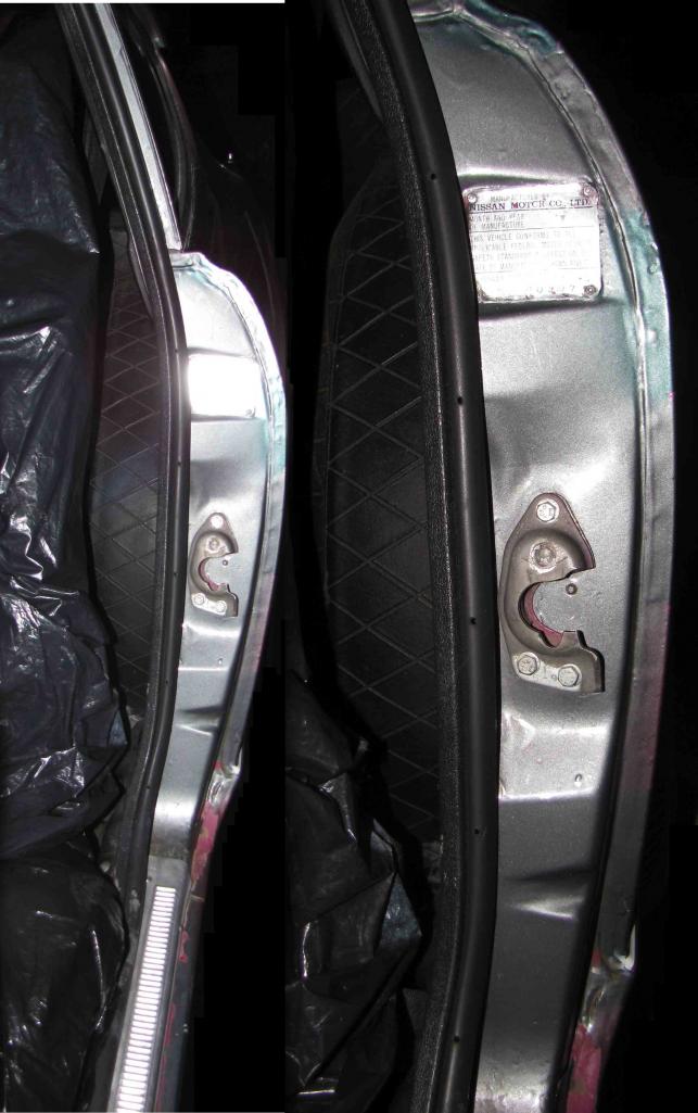
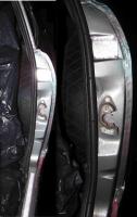
INST3D, Here are a couple of pictures of the door jamb (early 240Z)

-
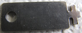
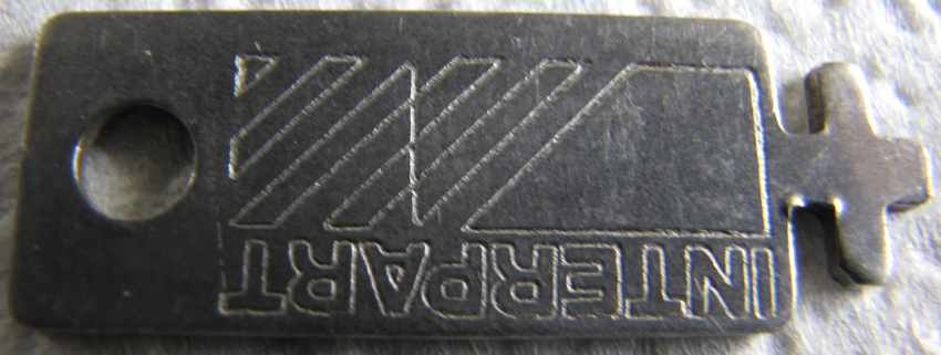
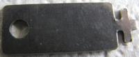
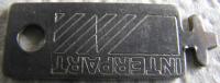
Up for grabs here is a truly rare item, a key with the word "Interpart" on it that I believe to be a louvre key. I put a Chastain shadow louvre on my car but this ket won't fit it. If this is something I need for my 1970 240Z someone please enlighten me to so I don't give it away but I can't imagine that I need the key. Yours free, I will even pay postage though I imagine it will be quite a bit for such a large, heavy unwieldy item. Front: Back:
-
Did the gauge get stuck as the tank went from full towards empty so the gauge would read full okay but not go lower than a half tank reading as the tank emptied? If you get wires with alligator clips from radio shack you can then set the sending unit on the ground, set it for 90 ohms, connect it to the wires it normally connects to without disturbing the sending unit, turn on the ignition to see if your gauge reads empty as it should if the sending unit is showing 90 ohms (might double check to see if the sending unit is still showing 90 ohms as an open circuit will also give a reading of an empty tank). I used long enough wires that I could sit in the car to do that test. Give the gauge time to respond that thing takes forever it seems to get to a reading. Inconsistent reading with the ohmmeter is an indication of needing replacement IMO unless you want to try fixing the one you have. There are other postings on fixing it.
-
Assuming the small diodes you have are for powering the voltage regulator (not the larger ones for powering the car) then I believe you need all three diodes instead of just one because the voltage out of the alternator is three phase and by using one diode you would have the voltage regulator turning on and off causing the alternator output to be turning on and off. Using three diodes lets you take advantage of the overlapping three phase current to give a much smoother voltage for the voltage regulator to work with. Hope that makes sense. With one diode you would get wild voltage swings coming out of the alternator because the voltage regulator would be responding to the wild voltage swings fed to it.
-
Did your car always do those things or are they all new behavior? My personal favorite is to go berserk.
-
Zed Head, In reading on the net it looks like the banded ends (cathode) of the diodes all go the same way whether the diodes are used for the alternator rectification to power the car or whether they are used just to power the voltage regulator as apparently some alternators use two different sizes. The diodes that power just the voltage regulator are smaller. Just orient the new one like the other two diodes as far as where the banded end is connected and you should be good.
-
Captain Obvious, I admire that kind of resourcefulness, making a part from something else. How did you make the brass insert?
-
Nice work, I have wondered what could be done in making a wood knob. I wonder if something that nice looking could be done with a drill being used as a lathe instead of an actual lathe?
-
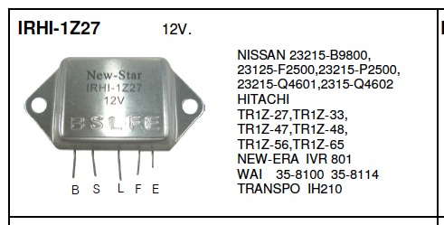
Can you read any numbers at all on the diode with a strong magnifying glass or jewelers' loupe? Try typing in the numbers on the black part, I typed in 35-8100 and it came up as an automotive voltage regulator made in China though the website listed below has a minimum order of 10,000 of those gems. http://www.enginesworld.com/alternator-regulator/4.html Probably need a voltage rating of at least 20 volts, maybe a few amps. Need to know which end of the diode went to which wire, usually there is a band or other mark on one end.

-
Captain Obvious, Thanks for the offer for the damper stalk, turns out they are different though I got lucky and found a round top carb damper locally I didn't know at first was available. I was able to put the brass cylinder end of the bad damper in a drill chuck (took a few tries, the chuck just barely could grab the end of the damper stalk) and managed to spin it to check for bends, none found. I installed the new damper stalk today and now both damper stalks pull up smoothly with the same force as I gather they are supposed to. Nice feeling to see that after chasing this around with everyone's help. The car runs great now though I also synchronized the carbs, adjusted the mixture nuts under the carbs using the pull up opposite piston procedure and set the idle speed with help from the forums here all of which no doubt helped. Mike
-
That link wanted me to install software. Your post reminds me of when I first turned the key to start my 71 240 I had back in the 70s after putting new rings/ bearings in it. I also replaced the timing chain. I was afraid of monstrous backfires or other anomalies but all it did was run very slow because the timing was retarded due either to the timing chain replacement or how I put the distributor in.
-
I had a 73 240Z for a few years that had been kept in a garage and covered. The car cover that it came with looked like solid vinyl with a different soft material on the underside and apparently did not breathe. The cover worked okay while the car was garaged but when I used it outside not knowing about breathability it fogged the paint on the hood. (anyone have that car?- it was in Northern Calif)
-
bhermes, In looking at the pictures of your tank, your float appears to be turned 90 degrees to the way mine was laying on the bottom of my tank assuming your two pictures showing the float are upside down as I am perceiving them to be. Your tank looks different than mine so maybe your sending unit is supposed to look that way. Anyone know if some Z car tank floats rest an end on the bottom of the tank as bhermes' gas tank pictures in post #44 seems to be showing?
-
On my sending unit I checked the continuity between the two posts with an old analog multimeter on the resistance range with a needle instead of a digital display. That way as I slowly swung the tank sender through its range I could more easily see if the resistance smoothly varied between extremes of resistance (I measured 11 (full) to 80 (empty) ohms, others have measured closer to 8 on full). If the meter needle went to infinity frequently indicating an open circuit then I knew the connection between either the coil and the wiper arm or between the wiper arm and the post it connects to was not as good as it should be. I did the resistance checks using alligator clips to keep everything connected. My unit needed help, so after I sanded the coil of the sending unit (and soldered a wire from the wiper arm to the post it connects to) I tested it in the car by connecting it with alligator clips to the wires it normally connects to and then swung the float slowly through extremes of motion remembering my pertronix (back then) so as not to leave the key on too long for testing. Here is another post on adding a wire: http://www.classiczcars.com/forums/showthread.php?t=35258&p=318623&viewfull=1#post318623
-
INST3D, That drawing is really looking good. Mike
-
I couldn't get the filler tube off the tank of my 1970 car this summer either, eventually it fell off with my wrestling with the tank in violation of murphy's law. Learning from retrospect I wonder if I had heated the part of the filler tube that is on the tank with a hair dryer or heat gun would have helped? I noticed when I heated my filler hose with a heat gun at the top where the gas goes in so I could push it through that area that it went from rock hard (probably was the original filler hose) to extremely pliable. I did get carried away and managed to push a hole in it with a screwdriver but the hose was being replaced anyway.
-
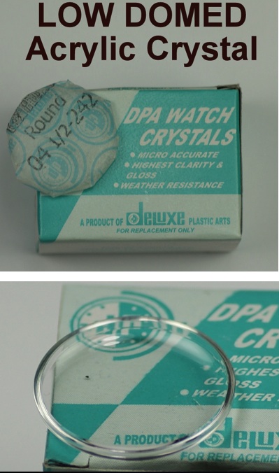
GongZ, Here is a snapshot of the eBay listing for the acrylic watch dome to make this thread longer lasting. Great idea on using a router! Nice graphic showing the process of making a map. Mike