Mikes Z car
Free Member
-
Joined
-
Last visited
Everything posted by Mikes Z car
-
 For car cover protection I thought of sewing on patches to make it look like it was repaired. I like the wrap idea with the phony rust. Ha!
 -
I didn't think of this until after I saw grannyknot's eBay picture of the clamp showing what appears to me that the rubber block on the clamp is supposed to be in contact the crossmember but I am aware that the parts car in the pictures I posted got hit on the right front wheel good enough to require new front wheels. It also was enough to bend the front frame rails. I guess it is possible that the impact turned the clamp and changed the rubber clearance. The clamp shows no sign of damage and the steering rack looks okay.
-
Crhis, You are welcome. It would be interesting if someone would look at the clamp on their car to see how close the rubber is to the crossmember. Good observation, maybe to be effective it should be closer to the crossmember because it would kick in sooner that way.
-
I had removing the rotator cap work once. They ran the battery all the way down trying to start it but I got to keep the car. I have crazy ideas like a recording that makes the car sound like it is turning over when it isn't. Specifics might not want to be shared. There are immobilizers that come with alarms. New cars use immobilizers but the complicated electronics running the engine makes them hard to defeat.
-
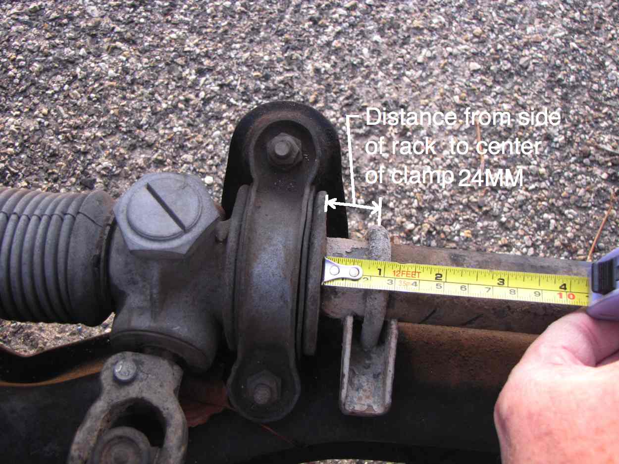
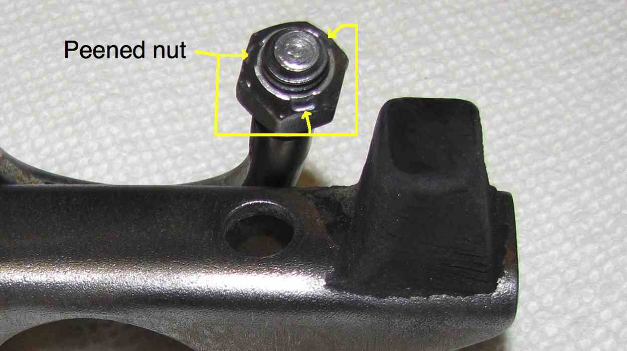
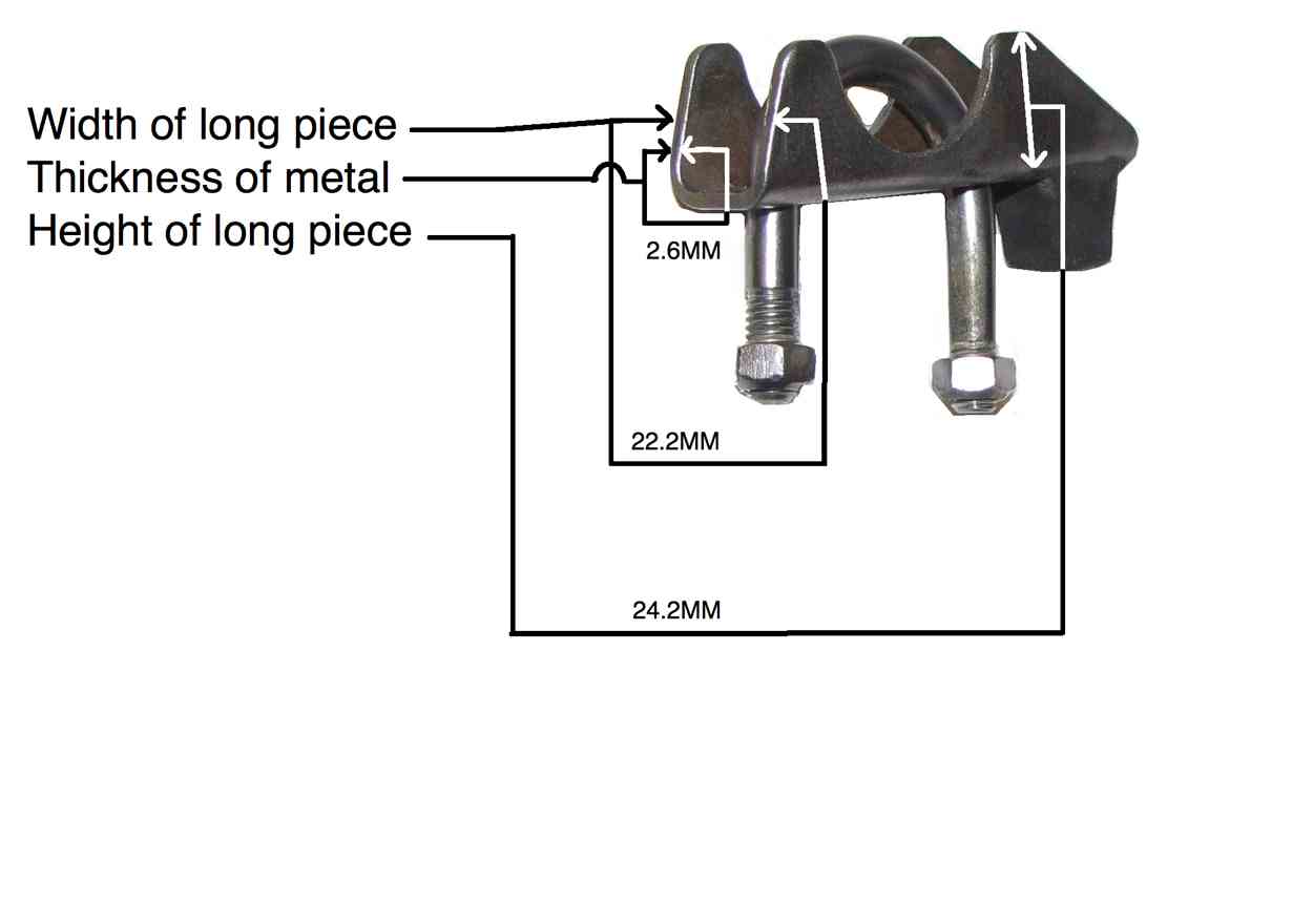
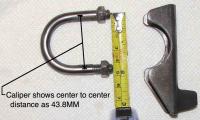
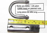
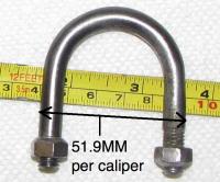
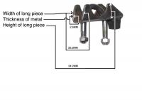
grannyknot, These are all the measurements I could think of, let me know if there are other measurements that might help. I noticed one of the bolts has more threads than the other but as far as I can tell there is no significance associated with that. I wirewheeled the part to make it easier to see. Distance from rack mount to clamp 24MM: Rubber clearance to crossmember: Bolt size, length of long piece: Bolt center to center distance 43.8MM by eyeballing caliper: I am no expert on hardware but the nuts on the clamp appear to be peened. I noticed they took a little force to get off: Outside measurement bolt to bolt 51.9MM: Width, length and height of long piece:


-
grannyknot, I will post some measurements and pics. I will need to be able to duplicate where it is on my parts car anyway to be sure I get it on my driver car properly. If I post info and you see that you need additional info guide me on what would be helpful. I hope I can get it off okay. Mike
-
Good advice I will move that clamp on my parts car over to my car. I didn't know the clamp was for safety.
-
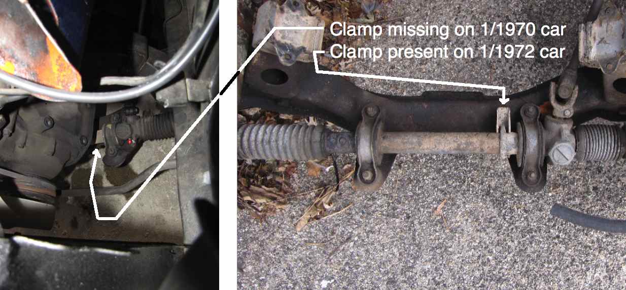
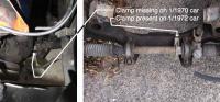
Interesting. I just took pictures of my car and a par ts car. The 1/70 model is missing the clamp and the 1/72 model has it: I know the 1/70 car was raced, don't know if they had any problems with it though even if they did they might not have known the corrective action.
-
I spotted a 71 Z for sale in 1977 at a used car lot. I bought it and liked it so much I would drive out to a parking lot next to the main drag and watch cars go by because I just liked sitting in it. It seemed like a magical place being in that car. Never felt that way about any other car except for the Z I have now.
-
Thanks for posting! Those articles are really interesting to me.
-
Thanks Chris, I had heard about the 24V idea for cars being looked at and then it never materialized. I wonder if the box was made in anticipation of selling 24 volt headlights? The 6024 bulbs I see on the net are rated for 12 volts. The LH after the 6024 just means low beam high beam I assume.
-
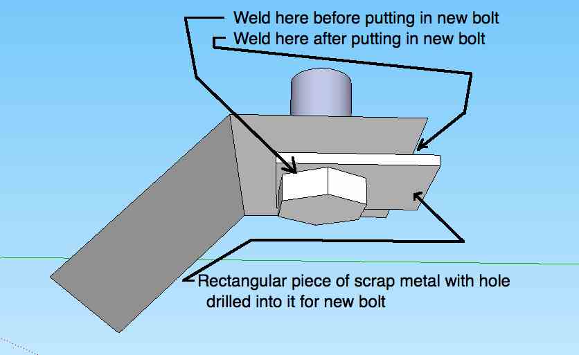
Drilling out the bolts would be a lot of work but if that were done it might be possible to do a repair as shown in the drawing if a new bolt is chosen so as to be long enough to compensate for the thickness of the scrap metal used for repair. Maybe someone else could weigh in with their ideas. If the bolt doesn't want to come out when drilling keep making the hole bigger until it does. The straps those broken bolts go through could possibly be bent upwards somewhat for easier access to the back side or even the end cut off and welded back on with a new bolt. I have used a dremel on my car and have had good results in tight places for cutting/grinding though I did have to replace the drive belt once. Some of them might be direct drive. I have used an ordinary drill with a grinding stone also with some results. FWIW.

-
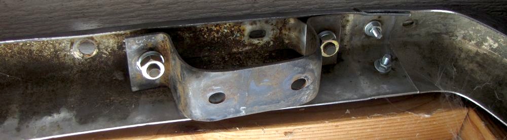
I won't be able to help though this picture of a bracket on a 240Z re ar bumper may be a reference for someone else. I had a struggle replacing the nuts and bolts on this bumper.

-
Hi all, I added relays to the turn switch to take the current load off the switch by copying the idea on the website below. The mod is reversible and by doing so will leave only hidden soldered wires inside the clamshell as the only evidence it was done unless holes were drilled to mount the relays. With this setup the heavy current still flows through the fusebox but only a small current flows through the turn switch itself. I followed this website posting but I used a different brand of relays and added a connector strip; I am grateful for the information: 240Z Turn Signal Switch Circuit Modification The link above is to the article contributed by: Peter Paraska As in the article I took the switch apart to scrape clean the contacts though I also sprayed all contacts with deoxit contact preserver. IMO an easy alternative to relays is to clean the contacts only and not install relays; the switch with cleaned contacts should last quite a while. I went with relays because my DD uses them, it is an 83 model and has never had a light switch problem. Inside the turn switch I soldered the rivet where it makes electrical connection as the fuse box uses similar rivets. This was done in case I return the circuit to stock, this soldered connection isn't used with relays: Turn signal switch in action, ball bearing not shown (click for animation): I have read that newer cars have one contact on each side of the "see saw" where my switch has two. I ran fine sandpaper through the two upright springy contacts being careful not to bend them back too far so I wouldn't permanently bend them however these two contacts are not used for heavy current with the relays installed. I had read that others had taken the similarly constructed headlight switch apart more than once and sometimes the tabs that hold the switch circuit board in place break off if they are bent too many times. To avoid that I bent the two corners of the smaller curved metal side of the turn switch cover out as the corners only have to bend at a small angle before the tab releases the switch circuit board thereby reducing metal fatigue. I used channel locks to squeeze the switch cover back together during reassembly as a parallel force in line with each side prevented twisting of the cover. Note that IMO it is easier to get the bearing back in if the switch is taken apart by bending the tabs rather than what I did as the reassembling parts approach each other straight on then. Ball bearing: I added a Radio Shack white strip connector to make it easy to troubleshoot/correct any wiring errors if needed. Schematic and picture of my adaption of Peter's circuit: Note that on the back of my turn switch circuit board I soldered together the white Red and Green Black wires to improve reliability as this puts two contacts in parallel. If one contact should fail the other will likely still do the job. I did the same with the White Black and Green Red wires on the turn switch for the right turn relay. Newer turn signal switches have one wire where mine has these two I understand. Relay mounting- works, but I may not leave it like this: The relays I used are the same kind described in the article, two triple pole double throw relays, but they are a different brand. Peter used a radio shack relay, part number 702012. Note that a relay rated for 15A at 240VAC isn't the same as a relay rated for 15A at DC. The DC current rating is what is important here as generally relays can handle more AC current than DC. To make sure I don't forget how to revert to stock wiring I printed a copy of the schematic and the picture of the wiring layout above and taped them to the inside of the clamshell. Mike **************************************************** This may or may not be obvious but triple pole relays are not the only option for this mod. Other relay configurations will work depending on your creativity. One possibility would be to use 6 single pole double throw relays. Each triple pole relay could be replaced by three single pole double throw relays with the three coils wired in parallel. My feeling is that triple pole relays are easier to wire because of how I think about the wiring process but someone else might work fine with another relay configuration.
-
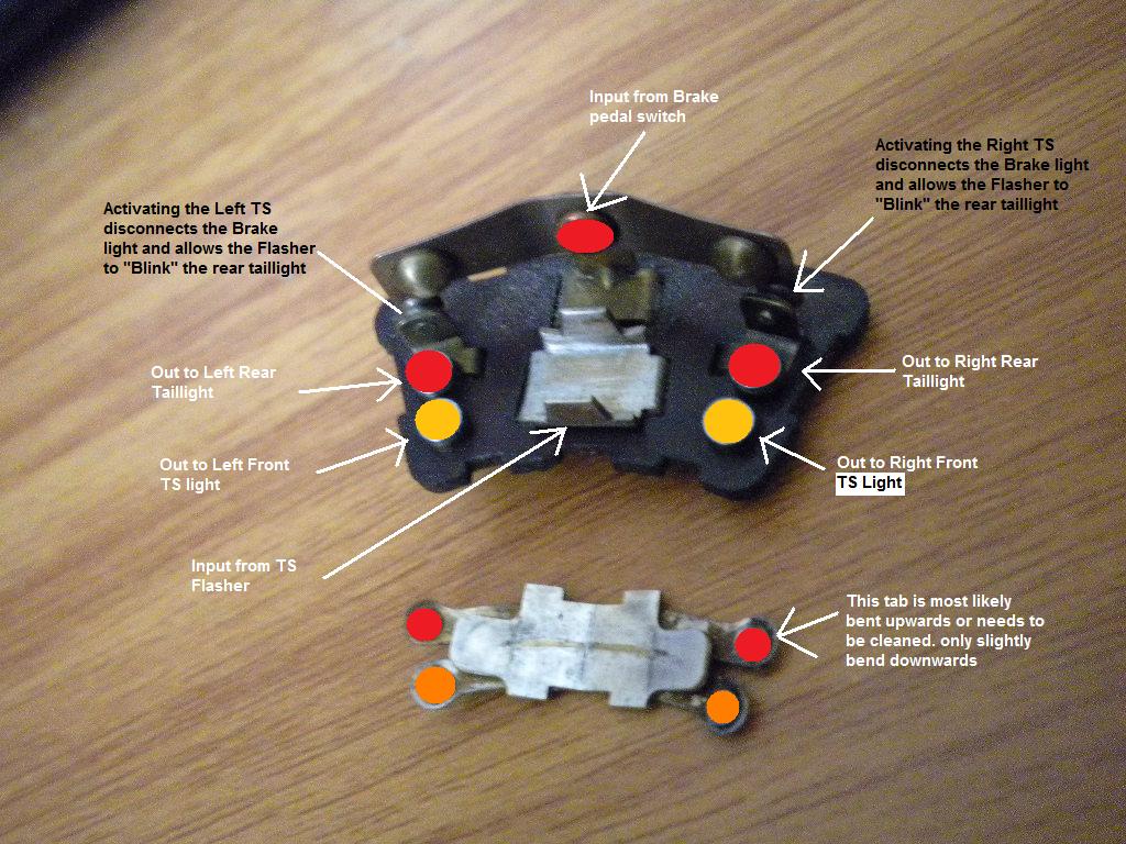
I purloined this drawing from a nice gentleman who made it. It is for the earlier 240z switch. I believe I read that later (1972) 240Zs have one contact on either side where this earlier switch has two adjacent contacts. If the driver brake light and a turn signal don't work I am thinking each problem is being caused by a different contact so that there are two problem contacts. Does that seem reasonable?

-
It is possible to lubricate both blower motor bearings without taking the motor out of the car to stop squeals or other noises related to motor bearings. I realized this after I had taken the motor out to lubricate the bearings. Many have opted to replace the existing blower motor and fan with a Honda civic heater fan. I like to fix things so I oiled the old motor because it was turning slowly and was squealing. Oiling both bearings with the fan in place in the car can be done by taking the end cover plate off of the motor keeping an eye out for the 4 washers that may be on the motor shaft. There were four on my 1/1970 car with one of the middle ones being a red fiber washer I imagine to reduce mechanical noise transmitted to the motor housing. The washers can stick to the end plate when it is removed and then drop off if they aren't noticed. The rear bearing is easy to lubricate with a light lithium grease or other suitable lubricant as it is a part of the end plate. The front bearing is easily accessed for lubrication with an old fashioned oiler that squirts oil or possibly by using WD-40 with its spray straw. WD-40 is explosive so if it is used a good airing out of the motor before reassembly might be a good idea. There are two magnets in the motor with a gap near the top of the motor between them of maybe 1/2 inch. An oil can with a long nozzle that squirts can be inserted in this gap to squirt oil up to the front bearing. WD 40 could also be used by inserting the straw that comes taped to the can in the same gap between the magnets that an oiler would use. The top gap would be preferred for the oiling as the oil can flow down to the bearing though the bottom gap can be used. When replacing the motor end cap be sure the tang gets aligned with the rubber grommet for the wires. If this isn't done the motor end cap can be installed 180 degrees out from the proper position resulting in it being slightly cocked over at an angle due to the tang sticking out which would not be good for bearing alignment with the motor shaft. Rear bearing can be seen here: Since I had already taken the motor out of the car to oil the front bearing I sat it on a workbench with the fan side down and poured motor oil into the gap between the magnets knowing it would flow down to the front bearing. I could not get the fan off and remember reading a thread where someone else ran into the same thing though your situation might be different.
-
-
-
I hadn't thought of the rattle idea. How did you bend the metal so neatly? I don't think I have good enough metal working skills to duplicate what you did.
-
The 1970 car I have has a tee at the top of the filler hose and no ex pansion tank. One hose from that tee goes down through the floor a few inches in front of the filler hose to act as an overflow drain to the ground. The other hose from the tee goes towards the back of the car, through the floor at the right ta il lig ht assembly to the top of the ga s tank.
-
madkaw, Thanks for looking it up! What did you cover the aluminum with? Mike
-
Took the heater blower motor apart to relube it to stop the squeak.
-
Thank you Blue for raising my awareness. This may explain some of the low prices of Chinese goods something I have wondered about.
-
Dan, Thanks for the pictures and nicely detailed explanation. What glue did you use to get the jute to stick to the firewall?
-
I responded to the other post now see the listing you posted here that describes marks on the car. Hope they find it.