Mikes Z car
Free Member
-
Joined
-
Last visited
Everything posted by Mikes Z car
-
 I like all those sounds but also the sound of the key turning in the ignition though that could be a part of the starter sound.
 -
Lee, Do you have any other pictures of the underside of your car with the tank out? I have been studying the frame in that area for spraying the inside of it. They can't be sent by PM I don't think. Maybe you could put them on your blog so they don't wind up on this thread? Thanks, Mike
-
That tank looks really good!
-
There was an adjustable wing on the back of my 240 when I got it. That was the first thing I took off.
-
Is there a radio?
-
Thanks psdenno, I think I can make that work using a flat wire like what I find in the street from street sweepers. I have used those seemingly worthless wire brush parts from street sweepers to fix other things already.
-
The resistance is too high. You will need a total resistance of about 1 ohm for the whole grid. That material has 250 ohms per square. If a line of that material on the glass was 1 mm wide and 1 mm long you get 250 ohms already without making it any longer. With it that short the resistance is too high already.
-
Is there a way to fix the thin part at the very bottom of the console that goes under the radio? It has broken off on my console.
-
I left a couple of things out from my previous post. I have had a couple of enthusiastic thumbs up from a neighbor and a visitor of anther neighbor. Ten minues after I bought my car a few years ago driving it home I stopped at a gas station and the driver in the next car said he'd wished he had put cartoon characters on a car he had had. Last year I had it parked to go in a hardware store and came out to see a group of folks looking at it as they walked back from a fast food place for lunch.
-
Thanks Mike hope someone else can benefit from it. Mike
-
You can view the page at http://www.classiczcars.com/forums/content.php?178-Hatch-anti-corrosion-interior-passageways
-
You can view the page at http://www.classiczcars.com/forums/content.php?177-Map-light-stuck-fix
-
Any interest in my car would be easier to analyze if the PO hadn't painted Pebbles and Bam Bam on it complete with the painter's signature. Still, with the cartoon characters I love owning it. In my signature picture you can just make out Pebbles on the left rear quarter panel just aft of the antenna mount.
-
I hope this is related enough that it isn't threadjacking but I have wondered about the possibility of cutting an access holein the metal under the finisher to access the area behind the door striker plate to clean that rust prone area towards the wheel well out and maybe periodically spray it with anti corrosion material. I take it that area must be partly structural? Is there a way to cut a hole and weld in a removable door there? Mike
-
Blue, When you saw the breaking loose, what broke? Did the hook or towing eye straighten out or did it pull out of the threads they were screwed into? I always thought I wanted a tow eye in case I needed to get pulled out of a ditch. I did put my previous 240 in a ditch once on an icy road. Didn't hurt it though.
-
Is it that it isn't watertight? I have that latch in a bag here due to some work I have been doing on the hatch, sorta like cheating but I can't figure it out anyway.
-
Hi all, I went to spray the interior metal passageways of my 240Z hatch with a Transtar Amber anti corrosion spray can and noticed there is a reinforcement plate on both sides and top of the hatch. To spray the two passageways created by this plate on the sides was easy as I just had to guide with my hand the 3 foot long spray wand above and then below the reinforcement plate as you can feel the end of the plate with your hand. See drawings. After I did this on both sides I drilled a couple of holes at the top middle of the hatch to give access to the top and bottom of the reinforcement plate in that area. Access to that area can also be had without removing the hatch as I did by drilling in the corner, see last drawing. Be sure the two corner holes line up with the two passageways at the top of the hatch especially if you use the Transtar spray wand as it isn't flexible enough to go around tight turns. I plugged the holes later with plugs I got at an auto parts store and sealed them with silicone. The animated .GIF drawing shows the location of the reinforcement plate. The end of it can be seen by looking up in the bottom inside area of the hatch with the interior finisher removed. Mike Where I ran the spray wand on sides of hatch: Black U shaped area is reinforcement plate (click for animation): Drill two holes for spraying top of hatch: Transtar Amber Spray can (spray can on left): Wand used was 3 ft long, sprays 360 degree pattern: (I found mine in a local automotive paint shop, can also perhaps find with google) #4471 Transtar Rustproofing Wand (includes three 3 ft wands and shorter red wands):
-
Hi all, The map light in my 240Z got stuck so that when the switch was pushed in to make it turn on or off it would push in and wouldn't pop back out. This was largely due to the top and bottom of the assembly pushing in on the clear plastic switch cover causing the clear plastic to drag. To cure this I glued in a sawed off ordinary lead pencil to bow out the top and bottom of the assembly reducing the friction on the clear plastic switch. The pencil length that worked well for me was approximately 26/32 of an inch and was epoxied in place when it was working right. I painted the yellow pencil gray to hide it behind the clear plastic better. A small bolt with a series of nuts would likely also work and would be adjustable but use lockwashers if you do this. Final result: Light off Light on I also put a small amount of light machine oil on the switch itself on the white plastic post that sticks out of it and used a pocket knife to scrape smooth the plastic adjacent to the moving end of the clear plastic switch to make it more slippery. The plastic seemed to have dirt on it that was causing friction. Note that the clear plastic switch cover on my car would come out of the white housing on either end once the heater fascia cover was unscrewed for access to the map light. Mike Modification notes: Bottom View of post location: After modification before installing in car:
-
Would you pay 5$ for that car for parts? Sure you would!
-
Is there a possibility if it is a digital meter that it might be reacting to the voltage pulses from the coil and an analog meter might give a different (lower) reading? If so would the digital meter give a different measurement at the battery due to the battery absorbing the pulses?
-
This will describe the lock latch modification only and will not address the door warping issue further. I noticed the glove box door on my 240Z would not always stay latched. The first thing I tried was to slide the lock mechanism fore and aft after loosening the two screws that hold it on as they are in long slots. I had previously modified the latch on the door to stay in position better using a cotter pin (see part 1 of 2 blog post on this) but the half with the locking mechanism needed work so that the latch would hit at the right angle. I did this in two steps. To do the first bending operation I pushed in the lock with the key so the vise grips wouldn't hit where the key goes in and used an aluminum rod 3/16" in diameter as a fulcrum. Step 1: (click for animation) Step 2: (click for animation) The second bending operation used vise grips on both sides of the very end of the tang to slightly turn the tang so the latch would hit at a better angle: The door closes every time now with a firm click and stays closed. Be sure to click on the last two pictures below to see the short movies showing the latch before/after action. Jan 2012 Latch tang result from step 1 and step 2: Closing action before: ________Closing action after modification (click either for animation):
-
zKars, Thank you for the information and reminding me about the lube. I imagine the threads are basically good otherwise I would not have been able to get the bolts screwed in as far as I did. While previous owners have caused me some work I am grateful for their efforts at preserving the car as it must have spent most of its life in a garage based on its current rust free condition.
-
Hi all, I am trying to find out the diameter and pitch of the small machine bolts that hold on the glove box lock mechanism and the center console. Both appear to be 4MM but I have tried 4MM at .7 pitch available at Home depot and Ace hardware (thrifty now) (both in the U.S.) but they seem awfully hard to turn after I get them screwed in very far. Both of these places only sell 4MM in .7 pitch but I notice my die set has both .7 and .75 pitches. A P.O. had wood screws in place of some of the screws so the threads are chewed up a bit. I tried to put a metric 4MM die in the holes, both a .7 and a .75 pitch but neither turn by hand easily. Anyone know if there is a typical pitch used in the interior of an early Z or what they actually are? Thanks! Mike
-
My first 71 Z had an issue where I believe one of the butterflies in one of the carbs would stick on the side of the carb if floored (or something in the linkage). I had to be careful never to floor it. I wouldn't have known how to fix that then, not sure I know now either but the car I have now doesn't do that.
-
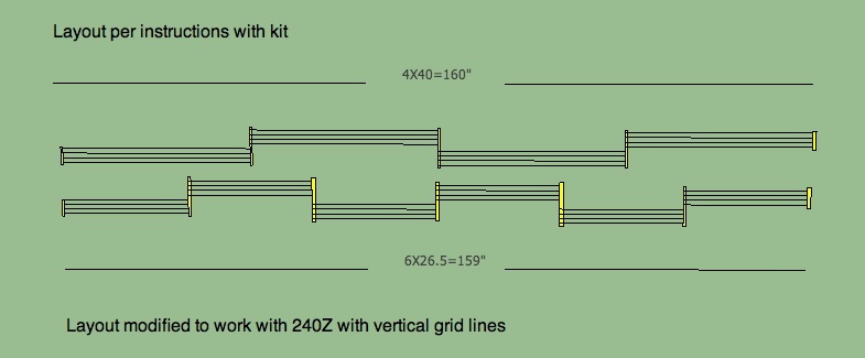
SteveJ, you are welcome for the write up. The attached drawing shows the minimum kit grid line length next to the modified layout I did to achieve that with the runs straightened out to make them easier to see. The bars at the end of each run represent the bus bars. Since the 240Z window vertical grid lines are approximately 26.5" each run you need 6 of them. If you use 4 runs the total grid line length is too short and you will have more current flow than the kit was designed for as shorter total length lowers resistance with resulting increase in current. The easiest way to reduce current if that is desired is to use 6 runs of 3 grid lines each run instead of the 4 grid lines that I used. Using three lines instead of 4 calculates to give 11.8 A. Note that the 15.7A with my setup is what you would get using the kit as designed on a 40" width hatch window so it should not be a problem. The total grid length has to be in the range of 160" to 246" whether you use 4 or 3 grid lines in parallel for all of the runs. Shorter than 160" and the grid will be hotter than the manufacturer designed, longer than 246" and the grid will be cooler than the manufacturer intended. Hope this helps. Mike