monkeyman
Free Member
-
Joined
-
Last visited
Everything posted by monkeyman
-
 It's a nice feeling when you manage to get something working! 220nF polyester capacitors should be easy to find to replace the 0.22uF electrolytic. I would certainly do that while you have the clock apart. And as far as the transistor goes, it might be ok, but I wouldn't trust it. It's a basic npn silicon transistor. I have fixed a few of these clocks now, and I have seen the transistor fail.
 -
Ron, Thanks for posting all those photos with the labelling. You didn't have to do any of that, so it is much appreciated. It helps with making sure the connection to the loom is done right. It's fine to have a working oscillator, but as you have said, the clocks can have a number of other problems that will keep them from working despite a functioning oscillator (I have seen the main motor gear cracked and missing a tooth as you have said, and the gear crumbles as soon as you touch it!).
-
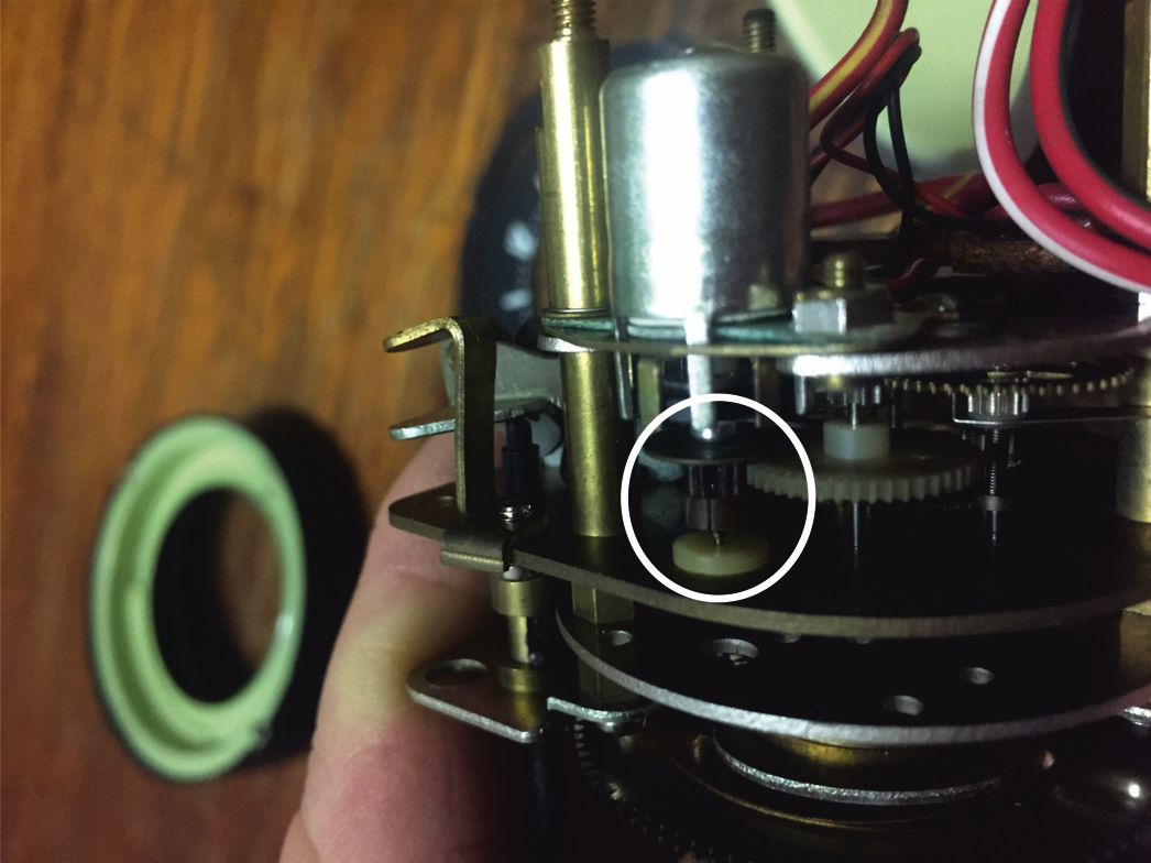
Blue = power supply, Black = earth. That sounds good. B and L are just the colour codes. Greg, If you look at your previous post with your hand-drawn sketch of the plug and wire colours, the drawing from the manual you include in that same post also shows the colours. The letters used in the manual match the letters you uses in your sketch to designate the colours. Only that B is used for Black, and L is used for Blue (as B is already gone). The motor won't go backwards, it can't. It has a 'pawl' to prevent it (remember, you were the one who told me about pawls). I'll put a photo in of the pawl. It is a kind of Spring-loaded arm. When the clock goes the wrong way, the pawl moves until the spring catches and it bounces back in the right direction. I will try to include a video of it working. When power is applied to the clock, there is a 50% chance it will start going in the wrong direction, and that’s when the pawl does its work. Applying power in reverse to our circuit won't do anything. The circuit is protected by a diode, it just won't work until the supply is swapped. I tested this a few times. d3c0y has said his circuit has protection against a reversed supply too. I think either would connect with a dedicated plug (in place of the oscillator box) to the clock harness without trouble. Just making sure the incoming +12V and GND go to the right place on the PCB and don’t need reversing. Our clock could be installed into an oscillator box with no changes to wiring either. Our oscillator uses +12V as the ‘common’ signal to the clock, and I believe the original oscillator wiring connects the clock ’common’ to the +12V coming from the car (where the Red and the Green wires join at what looks like the feedthrough capacitor at the oscillator). I was unsure of this but the more I read here the more convinced I am that that is how it was done. This matches our oscillator operation. I think d3c0y’s oscillator uses ground as the clock ‘common’. No big deal, but I think the green wire at the oscillator would have to be disconnected from the red wire at the feedthrough capacitor and connected to the ‘common’ pad on the PCB or possibly to the black wire somehow. That’s only if you wanted to install it in an oscillator box. I’m not sure how likely that is. rally clock pawl.MOV

-
Yep, a feedthrough capacitor makes a lot of sense. I’ve never seen one, but this looks like a good place for it. If it is a feedthrough cap then the wires going to it could be the +12V after all, and things start making sense. (Everything the Captain has written makes sense… and no, we aren’t reversed down here, but I think those left-hand drive Zs in the U.S. could be ;-) Greg, the wiring diagram you translated doesn’t look right. The colours you have indicated are reversed to the wiring loom I have. The wire you indicate as being blue (+) connects to the loom socket that has two wires coming from it on the diagram, one to the oscillator and one to the clock (to its case?). The other plug (you have indicated as being black) just goes to the oscillator. I have the colour of these two reversed on the loom I have here. The plug with two wires coming from it and connecting to the clock case is black, not blue. Could you have got the colours reversed in your translation? Gav, where do you store all this info? … must have a big head….;-)
-
From what I can tell from photos I have seen on the internet, I agree with the wire colours to the oscillator plug pins have on your diagram (though I don’t have an oscillator to verify it). From the wiring harness I have, the way the oscillator/clock harness wire colours match at the plug/socket are like this (using your pin numbering) Pin OSC PLUG CLOCK SKT 1 White Red/Yellow 2 Green Red/Green 3 Yellow Red/White 4 Black Black 5 Red Blue But although the harness I have looks original, a new socket was spliced onto it. I have assumed it was done right, but it’s possible it wasn’t. It’s interesting to note that both you and I have the White wire going to the Red/Yellow, and the Yellow wire going to the Red/White. It doesn’t matter at all as these two wires are interchangeable. Where we see things differently is where the black and blue wires from the clock go. The questions marks on your chart suggest you are not 100% sure, and the fact that the harness I have has been spliced means I can’t be 100% sure either. I think one thing that is certain is that the black on the clock harness is ground, as it connects to the case of the clock. The black wire to the clock and the black wire to the oscillator plug are crimped together at the socket that goes to the car. The other wire from the car is Blue and must be the +12V (or +13.6 as you more accurately have it). If my wiring harness is spliced correctly, then the Blue from the car (+12V) goes to the Red inside the oscillator, and the Black (GND) goes to the Black inside the oscillator. So the above table looks like this: Pin OSC PLUG CLOCK SKT SIGNAL 1 White Red/Yellow Signal A 2 Green Red/Green ‘common’ 3 Yellow Red/White Signal B 4 Black Black GND 5 Red Blue +12V This is different to what you have. I’m sticking with this (for now) because it makes no sense to me that they would use Black for 12V and Red for Gnd. The only reason I doubt this is that the Red goes to what looks like a stud on the oscillator case, which would be grounded through the chassis mounts. But if the stud is an insulated bushing passing through the case, then there is no issue (but then why would you not just run the red cable through a hole like the other cables?). Greg, Gav, are you able to confirm the wires going to the oscillator socket/plug at the harness or at the oscillator?
-
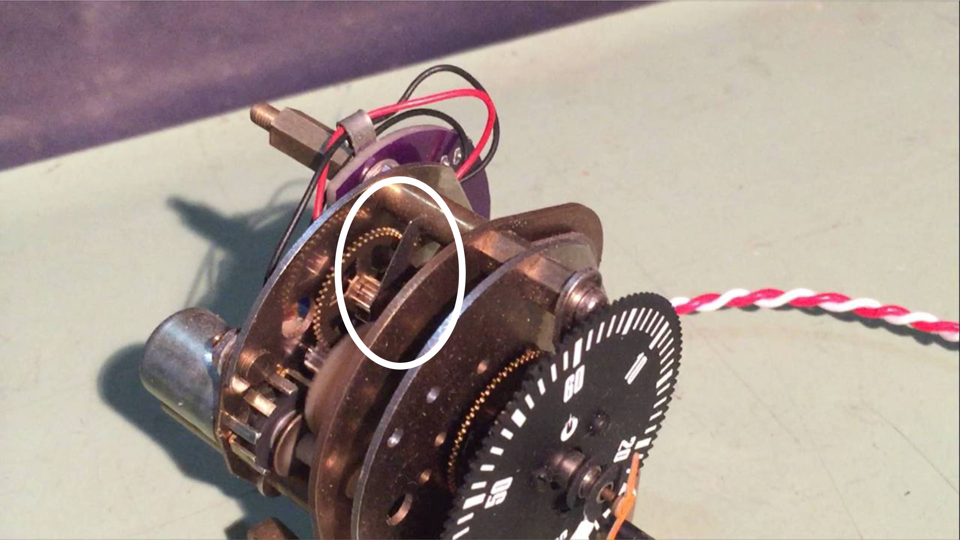
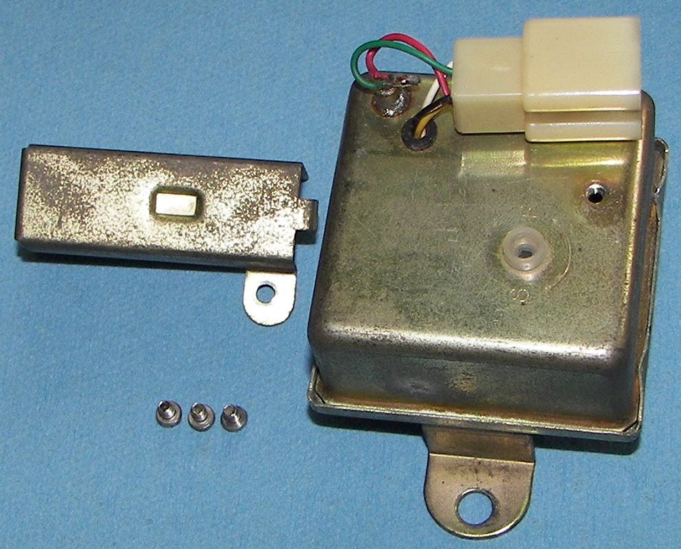
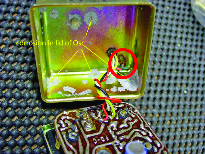
Those are some great photos. Very nice closeups. The part that interests me the most is where some cables come through the case. I have circled it. Is it an electrical bushing where the conductor passes through it but is insulated from the case? It looks to me like the wires going there are the +12V wires, and it doesn't make sense that they would be connected to the case. Do you have and close ups of that stud? From the top or below? Or are you able to measure the resistance between the bare wires going there and the case?
-
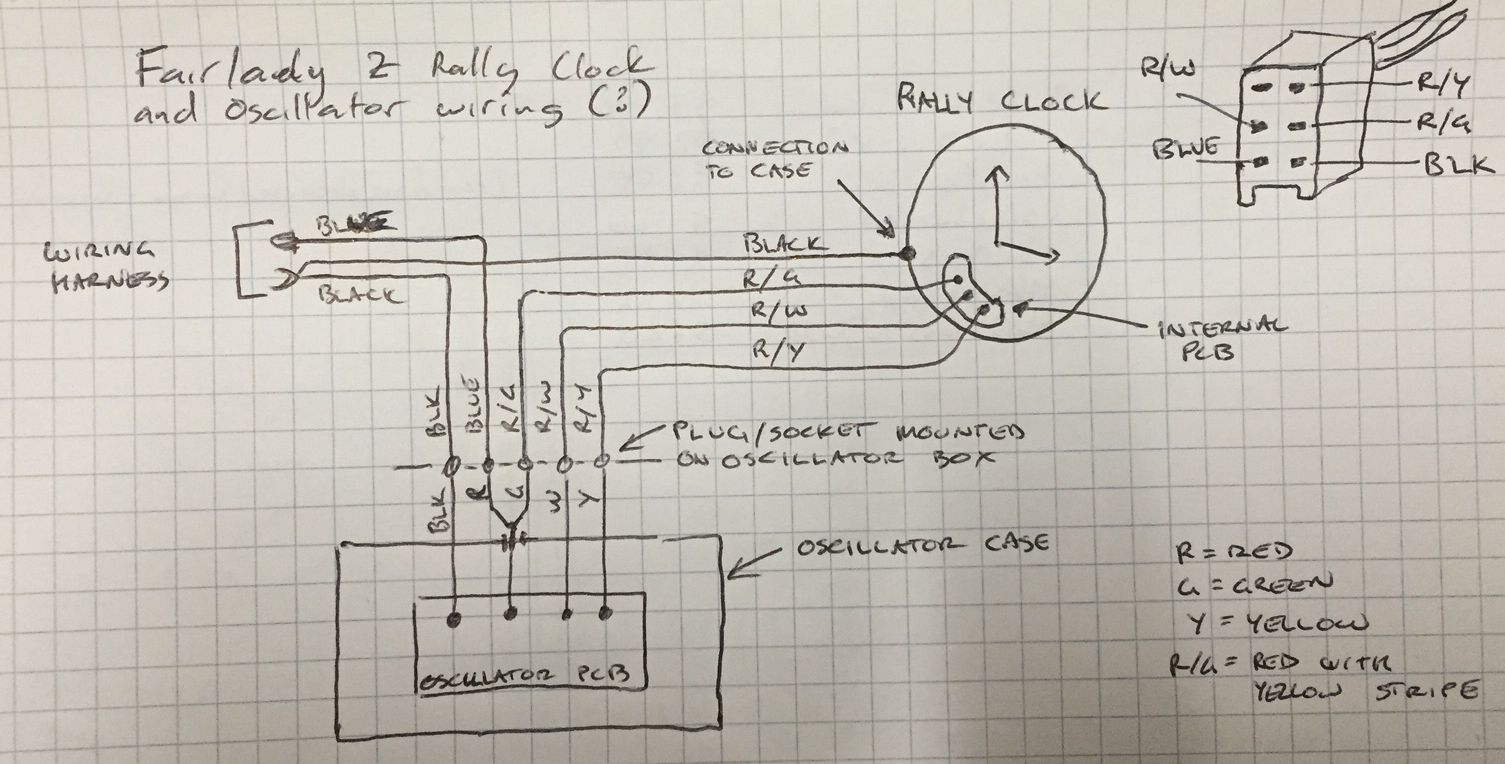
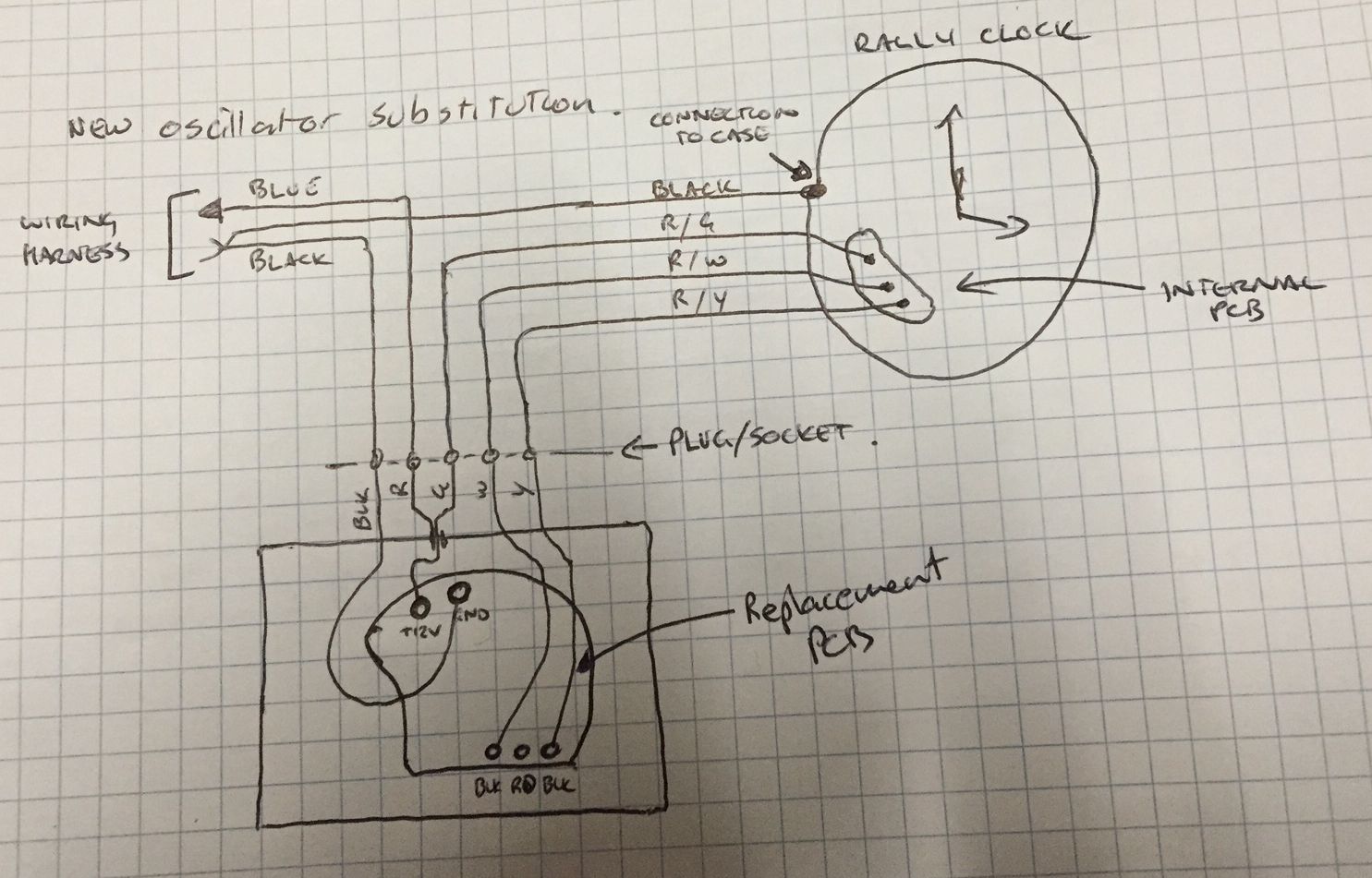
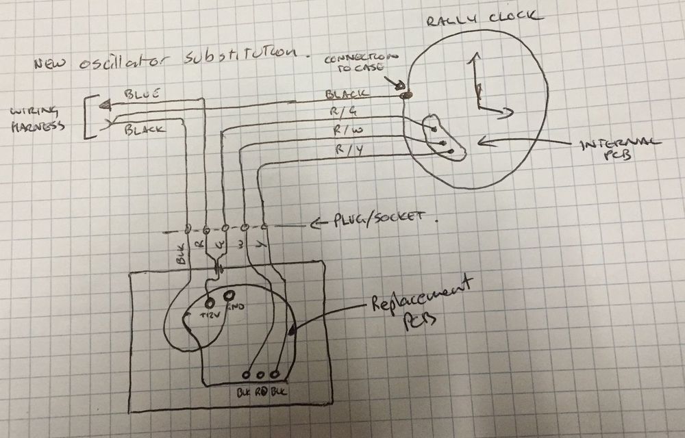
I don’t have an oscillator but I have a clock and a (hacked-up) loom thanks to Greg. As far as I can tell from what I have and from looking at photos of the oscillator on the internet, the wiring between car/clock/oscillator is like the sketch I attach below. One thing that puzzles me is there appears to be a stud on the oscillator case (under the cover that holds the plug in place) that appears to connect what I believe to be +12V to the case. And given the case then mounts to the car chassis, this doesn’t seem quite right (the black ground connects to the clock chassis… THAT seems normal). I am assuming it is some sort of bushing that is actually insulated from the case but passes though it (why they would do it that way I don’t know). There seems to be some sort of dag or lug there that isn’t clear in the photo. Are you able to do an inspection on your oscillator Gav? Could you take a better photo than the one below? I designed our oscillator to permanently apply +12V to the motor and switch the other end of the windings to ground (rather than the other way round). I did it this way as this is how it is done in the 260Z clock oscillator. If I have figured out the wiring with the rally clock oscillator correctly, then the same approach is taken here. That means our oscillator would swap right in without any changes to the wiring harness. It could be mounted in an oscillator case, or just plugged into the wiring harness if you could find a compatible plug. Like the attached sketch. Eric


-
It’s been a lot of fun working with Greg on this. Though that code is somewhat old and it’s changed a bit. Also, it’s from back when the clock I had to test with had a broken tooth on one of its gears. I then installed Greg’s custom replacement gear and got the clock to work better (so I could take more reliable measurements). As it turns out, that little cylinder in the clock is what I think would be called a 10-pole PMSM (Permanent Magnet Synchronous Motor). I found the frequency it required was much closer to 50Hz with a half-cycle time of 10ms rather than the 44Hz (half-cycle time of 11.4ms) I was using when I wrote the above test code. I also found a duty cycle of about 80% worked well, so I stuck with that and got rid of the adjustment pot. This might not be of great interest to anyone, but I felt I had to mention the timing errors in that posted code in case anyone wanted to do any tinkering of their own. Eric
-
Well done. You have done a very neat job. I say that through clenched teeth because we were only about a month away from putting our own oscillator out there! I have been working on this with fellow Z owner Greg Hassen. I have a rally clock, but Greg has done most of the testing. He has found some variation between clocks so we have put an adjustment knob on ours. To be honest, I can’t see why there should be any variation; the clock runs off a synchronous motor. I do know that the little plastic gear on the rotor shaft has a crack in one or two clocks Greg has tested, and this could be the cause of the variations. The clock I have also has a crack on the rotor shaft gear as well, in fact it is missing a complete tooth! It occasionally stalls and I expect this could be the cause (though mostly it seems to keep going despite the missing tooth, the momentum of the gears might be enough to keep it going). The pulse duty-cycle also seems to have an effect on the likelihood of stalling (I think around 80% gave the best results on my clock). I say all this because the cracked gear seems to be a common problem. If any of your customers has this problem and don’t realise it, they might unjustly blame your circuit. You should probably have them check the gear before selling them your oscillator, or at least inform them that the problem could exist. Greg has been looking at replacement options for the cracked gear. I will try to include a photo of my cracked gear. You can use it in your dealings with customers if you like. I think you have done a very neat job. And having been beaten to it, Greg and I debated whether to continue with our project. We think we might (it would be very unsatisfying to just drop it after all the time we have put into it, so watch out, you might have some competition on your hands!), and I think we could probably bring it to market for, say, $98.50 ;-) And if there isn’t much of a market, or you have already saturated it, then maybe would could collaborate instead of compete (I’ll have to consult with our Global Strategic Business Development Manager: Greg). Eric

-
Have the fuel hoses between the float bowls and the jets ever been changed? I had a similar problem to you. The aftermarket fuel hose which was thick, stiff and wanted to straighten would fight the spring that tried to return the jet to the fully up position. The Nissan hoses are thin and flexible, and are made in a U shape so they didn't put any downward force on the jet. I also gave the whole return spring assembly a clean. There was a lot of muck around that assembly which kept it from moving freely (and when you screw it all back together, don't do it up too tight or it will jam, use a bit of loctite). Let us know how you go. Eric
-
Dirty oil doesn't sound good, but I don't think it will be the cause of the problems you are experiencing. Oily spark plugs are not good. I don't know if you can do much about it without rebuilding your head or putting new piston rings in. Let's ignore that problem for now (it might turn out that when you get everything running ok, the oil isn't such a problem...). Sooty spark plugs mean you are running too rich. If you checked them in the morning after driving only five minutes with the choke on, then I wouldn't be surprised to find sooty plugs, so I assume you checked them after running a while. A couple of things to check: Are you sure you are setting the floats correctly? How are you setting them? Did you check that your jets are returning fully to the up position when you release your choke as JZM mentioned above? It would be very unsurprising if they get stuck (so your car continues to run rich when you finish with the choke). Is your ignition ok? You replaced the rotor and dizzy cap etc. Did you replace the points and condenser as you said you would? Sooty plugs can also be a sign of weak ignition (down the track you might think about a pertronix kit or similar). It also wouldn't hurt to check that the vacuum advance is working, and that you don't have any vacuum leaks that keep it from working. But definitely check that your choke is working properly when you switch it off. The jets struggle to get all the way back up when you let the choke out for a couple of reasons: The build-up around the return spring introduces friction so that it doesn't have enough force to get the jet back up. Also, if by now you (or a previous owner) has changed the fuel hose between the float bowl and jet with one from the general parts shop down the road, you can bet it is thick fuel hose and that it wants to straighten (so it fights the return spring as the jet pulls up). This will definity have the car running too rich. The Nissan fuel hoses are thin and made in a U shape so they don't put any force on the jet. It might seem that having the choke out works because the choke also adjusts the throttle. And one last thing: give the spark plugs a clean. Starting with sooty plugs is just going to confuse your trouble shooting. Let us know how you go.
-
Have you had a look at your spark plugs? If you find three of them are black and sooty, then the associated carb is running too rich. There has been some confusion about the float settings over the years. In some places/books, the float setting is the same front and back. In other places, this was revised so they were different. Also, if they fouled before you adjusted everything, they might still be problematic until they are cleaned up. Have a look at the spark plugs, they might tell you something. Eric
-
This thread is now pretty old, but I found my problem and thought I would post in case it helps anyone down the track. The shuddering/vibration had slowly gotten worse. I had my rebuilt gearbox put in and while I was at it, I replaced all the universal joints. No joy. I have ordered new rear wheel bearings and diff mount from Nissan. They have delivered them all except for two bearings that have an ETA of 30 December! In the mean time I have replaced my old tyres and voila! The vibration has gone! It was my old tyres. I just took the Z for a 8500km drive across Australia and I expect the old tyres didn't wear too evenly. I didn't expect the tyres initially because it would only happen on decelleration and at high speed. Well there you have it. I will still change the rear wheel bearings and diff mount when all the parts finally come in.
-
Bruce, I agree fully. I was kicking myself when I realised that my choke was stuck. At the time I was thinking it could have been the jet in the float getting jammed. I am the grateful owner of a couple of ZTherapy DVDs and in those the 'grose jets' are recommended. Are these still available? I couldn't find a supplier. Do Ztherapy sell them?
-
You were planning to check something: the float setting. Have you done this yet? My understanding is that a surging engine is often due to a lean mixture. This sort of matches the 'it's fine until it heats up' scenario. An engine runs hotter when the mixture is lean, and I think it is this heat in the cylinder that affects the way the mixture burns (I am happy for anyone to correct/clarify this). I have recently experienced something like this. I have a 260Z with 240Z SUs and it was all running well, the carbs were adjusted and balanced, then one day it started running like a dog (but it wasn't surging). I found the three rear sparkplugs were black with soot. The rear carb was running much too rich. I tinkered a few days, in the process I adjusted the rear float to run a bit leaner, but in the end I realised it was jus that the choke was stuck, this is why it was running so rich. (Why didn't I check the choke first?!) So now I have my rear carb back to normal but with a leaner float setting. My car surges a bit now. The hotter it gets (ambient or engine temp) the worse it gets. The temperature guage shows normalish temperatures, but I can feel a lot more heat under the bonnet. Everything seems hotter. It is raining today but I want to get the float back to normal. Sounds like you have the same problem. Make sure that when you find the problem you let us know. It will help the next person with a similar problem when they do a search. Good luck
-
Hi all. I have been reading through a few posts about the rear wheel bearings and had a look through the Atlantic Z Car club article on changing them. I am not sure my problem is bearings though. I was under my '75 260Z (Australian). I had it jacked up on stands with the hand brake on in readiness to swap the gearbox with a rebuilt one, and I was testing the uni-joints (I have a vibration when I release the accelerator at about 100kph). They seem ok (still planning to change them though). I noticed I had some play in the diff. I think I have always had some play, this is normal, right? What I noticed that concerns me is play in one wheel. I would rotate the propeller shaft backward and forward, neither wheel would move but the half shaft all the way up to the wheel flange on one wheel would move a little (only one wheel), as if the axle inside the wheel had some play. Is this possible? Is it just worn bearings letting the axle move or are the splines damaged? Anyone had this before?
-
Thanks for your reply. It can't be the strap as you mentioned, not during deceleration. My gearbox started giving trouble around the same time I noticed the vibration and I am getting my original 5-speed rebuilt. Once I have changed it over, I will look at it again. If it still vibrates I will do as you say and get the drive-shafts off for a better look at the uni joints. Thanks for the help, Eric
-
Hi all, I have been searching through the forums and have been reading a lot about diff mounts. I crawled under my car to have a look and noticed the diff strap for the first time. It has a fair bit of slack. Should it be like this? It is still in one piece. What my car does is vibrate or shudder when I let the accelerator go, but only if I am up around 110kph or more. I know my uni joints are good and the ball joints are good (had them checked twice). Drive shaft is balanced. The gear box is very unhealthy right now (but that's another story), but the shuddering doesn't change much regardless of the gear I am in, whether the clutch is in, or whether I am in neutral. From what I have read I will look more closely at the diff mount, but what is the diff strap supposed to do? Protect from further damage if the diff mount fails, or hold the diff snout down firmly (in which case I wouldn't expect any slack)? Thanks, Eric
-
Hi all, I posted the 'How to fix your early Z clock' a while ago now. I have realized that I made a mistake with the transistor pin-outs. I have fixed this error and will try to attach the document to this post. Has anyone tried using the 2N3904 transistor? I never heard much of whether this helped anyone, maybe it didn't because of the mistake I made. Is it possible to remove the document I originally posted? I would rather it not be used due to the mistake in it. Eric How to fix your 260Z or 280Z clock - rev 1.pdf
-
Where are you from? If you are in Melbourne, then there is a place in coburg that does it. Give the guy a call, 9357 2999. If you need any parts for your zed, ask him, you might be lucky. I haven't been there for a little while, and he has suggested that he was going to pack it in and give it all away (but I think he is just grumpy), so hopefully he is still there. Good luck Eric
-
I don't know about the 280s, but my 260Z has a 'fast idle actuator' that increases the engine revs when the A/C is on. A vacuum hose goes to a relay on the right hand side of the engine bay, the relay opens up a valve when the A/C is on that lets the vacuum through to the actuator. The actuator is just a vacuum driven puller that pulls on the throttle linkage. It is adjustable. I had to fix some vac hoses and adjust the actuator when I got my A/C running again recently. The 280s might be a bit smarter than the 260s and do things differently. If this helps, good, if not, good luck Eric
-
I am sure the Hotwire wheels on my 75 260Z are 14x7inch. The tyres I have on them now are 205 wide and I can't fit my finger between the tyre and the spring on the inside of the front wheels. I couldn't tell you the tyre brand at the moment (the car is at home), but they aren't anything expensive. As the car drives and the wheel spins, I expect the tyre will get a little thinner (if anything) and the clearance will increase, but I am not comfortable having the tyre that close to the spring anyway. Next time around, I will probably put 195s on the front.
-
Good point, I could have been a bit clearer on which clocks it applies to and how to tell before you pull them out of the dash. From what I have been able to tell (and this was not a thorough investigation), the earliest clocks were motor driven. They changed to the electric circuit driven type in 1974 I think (I have seen an early 260Z with the motor driven clock, and my 1975 260Z has the electric one). So unfortunately, this article wont help the 240Z owners out there. There is an easy way to tell. The motor driven clocks have the manufacturer name 'JECO' stamped on the face. The electric circuit driven clocks have 'Kanto Seiki' stamped on the face down the bottom (look closely, it is partly obscured by the housing). These are the conclusions I came to after tinkering with 1/2 dozen clocks. It also might be different here in Australia to elsewhere (though I don't see why). I think I will update the article, but will first wait to hear any other suggestions or criticisms. (Chris A has already mentioned a different clock this article applies to, and has found another equivalent transistor.... let me know if it works Chris). Eric
-
Hi all, There has been some discussion about how to go about fixing the clocks that are driven by the small electric motor. I managed to fix the type that are driven by a small electric circuit. I promised to write up something and post it. I finally did it. I couldn't help myself from drawing up a few things and trying to make my little write-up look nice. I was pretty happy with it and showed my wife last night. She called me a nerd! How do you like that?! I have attached it (hope this works) If anyone has any corrections or comments, I would love to hear them. Eric How to fix your 260Z or 280Z clock - rev 1.pdf
-
G'day Maddos, I like the photo of your zed. Mines the same (except the wheels). I think the metallic blue looks fantastic. As for the clock, you've noticed the tranny is an 828 (or something that you can't get anymore). I used a BC337. It is just a basic npn BJT we stock at my work. I am sure most common npn BJTs will do the trick. I found that when working, the 828 (or whatever it was) didn't have much grunt and replacing it with the BC337 gave it a bit more. The pin-out is different though! I have started writing up what I did and sketched a pin-out comparison between the two and another common BJT. You see the little copper-looking metallic disk. It appears to be made up of two windings. From what I gather, one is a 'pick-up'. It detects the magnets on the oscillating disks as they pass. This then creates a pulse, which drives the transistor, which then uses the second coil to give the oscillating disk magnets a little nudge as they pass the coil. Sort of like giving a kid on a swing a push each time they swing past you. I looked at the voltages at the transistor with an oscilloscope and the 828 didn't seem to give much of a push. I don't know if this was a design parameter or if the transistors back then were just junk. The replacement transistor gave it a stronger push and mine has been going strong for over six months now. Hopefully I will have some sort of write-up in a couple of days to post with pin-outs and waveforms. I will try to make it interesting.