FastWoman
Free Member
-
Joined
-
Last visited
Everything posted by FastWoman
-
 That's the trim panel affectionately called the "kick panel." If you sit in the passenger seat and kick your right leg to the right, your foot will hit it. You remove that trim panel to get to the ignition module, which is a black metal box of roughly (for memory) the dimensions 1" x 4" x 5". Personally, I'd bet against it being an ignition problem. Your run time before shutdown seems too random for that. I'm still betting on fuel.
 -
Also your testing for air flow through the vent system: You're examining the wrong line. Perhaps you should get some assistance on that issue. Will the gentlemen coming to your assistance get RB up and running? Probably. They sound like they know their stuff. Your main running issue will be something very specific, e.g. a bad fuel pump or a rusty/cruddy fuel tank. You might have to pull/service/replace the fuel tank, which is a bit of a project. However, yes, you will get running again. And as Rossiz said, your RB will become a reliable vehicle, once you chase down all the gremlins -- provided the engine block is basically sound -- good compression and such.
-
No, it's not an integrated distributor/ignition module. The ignition module is a small black box (literally) somewhere inside the cabin on the passenger side of the car. Mine is behind the kick panel, but I think the location might be slightly different for a '76. Jai, I don't consider replacing a fuel hose that difficult at any skill level. The most important thing is to buy the correct type of hose, cut it to the correct length, loosen and pull off the old one, and then install and tighten the new one. You only need a screwdriver and a knife. As others have pointed out, though, you will need to be careful with fuel hoses beneath the car, as gasoline can just start running out of them. You'll need to clamp them (and maybe should wait for help). However, you should be up for replacing those red garden-hose fuel lines in the engine compartment. I really think you should, for the sake of safety. I thought they were merely the wrong material, but from your description they seem also to be too large. Not good. Not safe.
-
Jai, I agree with Jonathan. Vaccuum leaks are not your most significant issue -- not the reason your engine is dying randomly. I have previously expressed a need to look for little issues such as vacuum leaks, because they do need correcting. BUT a vacuum leak is not going to suddenly kill your engine when it's been running fine for a half hour. It's important to understand that your engine likely has several issues, some big and some small. Right now, I strongly suspect the reason your engine dies is some sort of fuel starvation problem. It could be rust clogging up the system. It could be a failing fuel pump. But I bet it's one of the two. (My money is on the fuel pump.) Just to offer a competing theory, bad electrical connections can also kill your engine suddenly, either resulting in loss of fuel delivery or gross overdelivery. And then there is also the possibility of an ignition problem -- not the cap, rotor, wires, plugs, but rather the ignition module or an electrical connection. Once you get the engine running (without dying), then is time to set in on the smaller stuff -- electrical connections, vacuum leaks, etc. All of these create errors in fuel/air mixture, and all the errors add up. The improvements you see will be incremental, and reliability will get much better. IMO you should also replace your red garden hoses -- sooner, rather than later. The oversized "fuel" hose makes me very nervous.
-
Personally I think it's failure of the semiconductors -- most likely the mysterious black-box linear chips in the little "spider" cans. Given enough heat, usage, and time, semiconductors do go sour. Here's a little article about it that's a bit over my pay grade: http://spectrum.ieee.org/semiconductors/processors/transistor-aging/0 The most common failure mode for Hitachi ECUs ('77/'78) seems to be a shortening of the injector pulse, hence a leaning of the mixture. It would be difficult to trace down how/why this happens, because we know nothing of the proprietary circuits inside the mysterious little black boxes.
-
I'd install the Fram G3 (the little clear filter) and the main fuel filter. Then see what shows up in the Fram filter. They're extremely inexpensive. Go ahead and change the oil and filter too. No sense waiting on that if your oil is jet black. I will leave it to your local crew as to whether they are comfortable with you changing out ignition parts. My sense is that they would rather have you wait until they can have a look.
-
That's pretty much the same sort of thing I did with mine!
-
^^^ That really did have me doing this ---> Ahhhhhh..... Thanks! I needed that!
-
Excellent! (Phew!) Yeah, without tools, you would be dead in the water. I'm a fan of Craftsman tools. My parents bought me a basic Craftsman tool kit (along with basic tuning instruments and a couple of "how-to" books) back in 1978 when I bought my first car (a '75 Celica GT). Those tools have served me very well since then. I once had a socket crack (I abused it quite badly -- involved a sledge hammer, as I recall), and Sears replaced it. I also had a ratchet mechanism go bad, and they replaced the entire drive. Back when I worked for Sears, we would actually repair the ratchet with a refurb kit. But we were instructed to do whatever was necessary to fix or replace the tool, no questions asked. It's really special (a good karma thing) that your dad's tools are engraved. May they serve you and your son very well!
-
Jai, I think we've run into a somewhat expensive problem already: To work on your car, you will need tools -- much more than a hammer, an electrician's tool, and a pair of needle-nose pliers. The most economical way to buy tools is in kit form. Sears (now owned by Kmart) sells Craftsman, which is still a good make and is lifetime warranted. Apparently you can buy them from either Sears or Kmart. Lowes carries its own Kobalt line, which is also lifetime warranted. I have some of their tools, and they are decent too. I bought my son a Kobalt kit to get him started. Realizing you are on a budget, I checked Harbor Freight, but the kits there don't seem any less expensive than what you'd find elsewhere, and they frankly aren't as good. I would say you need the following basic tools: 3/8" socket set, extension, and ratchet handle -- metric 1/4" socket set, extension, and ratchet handle -- metric maybe a set of 3/8" deep sockets crescent wrench set fixed wrench set small variety of pliers -- needle nose, standard, channel-lock, perhaps vice grip screwdrivers I would expect to pay in the neighborhood of $100 or more for a basic tool kit that would have these items -- or maybe some kit that you would supplement with a few extra items. Sometimes these kits go on sale. Perhaps you could buy someone's tools used (maybe an estate sale?). But I don't see how you're going to do much work on your car without basic hand tools. EDIT: Perhaps you can borrow your son's tools? Does he have a set of basic mechanics' hand tools?
-
If Jonathan's method works (and he's used it, so he should know), go for it!
-
Light bulb moment: You can't simply take the Vout from the ECU and translate that to a meaningful injector pulse. You have to work RPM into the mix! The longer the air flows through the AFM at a given rate, the more there is to burn, and the more fuel is needed. So it's air flow times the rotational period of the engine that matters. Complications, complications... So AFM sets a ramp rate, with the ramp reset with each spark, resulting in a sawtooth waveform. A peak detector (diode feeding a cap, with a resistor across the cap allowing the signal to decay) monitors the peak voltage of the sawtooth, which essentially integrates airflow over time. THAT voltage then sets the threshold for the circuit I laid out.
-
Oh, and you want insanity? If I had the time and the right automobile -- a 1950's something or another -- I'd enjoy working out some sort of EFI using vacuum tubes, with the ECU glowing in all its glory, displayed proudly in the cabin like a "flux capacitor." But alas I have neither.
-
Resistor values? I dun' need no stinkin' resistor values! I fully agree with you about the mysterious analog voodoo circuits and the $$$,$$$ of research behind the original ECU. The closed-loop operation relieves us of some of those difficulties. We only need to get pretty close to the mark, so that the WB sensor can do the rest. And my overall strategy is different from Bosch's: They use fixed increment corrections, and I take advantage of the multiplicative properties of my ramp circuit to apply corrections proportionately to the air intake, as metered by the AFM. Unfortunately I don't know how much voodoo is built into the AFM. It's possible I need non-linear responses in the circuit design to complement the nonlinear AFM output. I have no idea without some sort of flow bench testing. (Of course we could use an MAF sensor instead.) But I do know this: The CTS modification on my car does get me running pretty much in the right mixture ballpark under low and moderate load, but my engine leans out and starts missing under high load. That suggests to me that the incremental correction for coolant temp, applied additively, should instead be applied multiplicatively. I don't know whether there were any good multiplier circuit designs back in the mid 70's. We did have some good multiplier chips from Analog Devices back in the early 80's. Somewhat related, I still own a 70's vintage Heathkit signal generator that uses a hot filament in a light bulb as a key component in its AGC -- clever, but not too impressive technologically -- and way, way too fussy for an automobile. I think a lot of the reverse engineering can be done on a test bench, to determine the magnitudes of the various corrections, relative to the base pulse -- or at least relative to each other. That would be a starting point towards figuring out each of the conditioning circuits that I've short-handed at the beginning of the schematic. And again, it's the wide-band sensor that will save the design and make everything good. The design objective should be to take as much of the burden off of O2 sensor compensation as possible. Anyway, this is not something I hope to do soon. I'm simply throwing out some ideas as a starting point. Maybe others will be inspired to tinker with the design. Who knows... I might too. I do look forward to breadboarding that ramp generator! But for now, I coughed up an idea, and there it is! And I have a place where I can come back and find it later. Done for now....
-
Thinking a bit further, one way to do the open-loop thing immediately after starting, before the wideband O2 sensor is hot and operational, is to have a timed relay that feeds IC5 with a pre-set Vr. After maybe 20 or 30 sec of operation (?), the relay would click off, and closed-loop operation would begin. Maybe the open-loop Vr would be based on the conditioned CTS input.
-
Goeff, it's carbs that scare me -- don't understand them -- don't trust them! They never seem to work right for me, no matter how carefully I clean out all their intricate little passages, and no matter what sorts of ritualistic kabuki dances I do. (Yes, I know SUs are special and different.) I've think I've finally gotten to the skill level that I can keep the mowers operational!
-
Surely you must admit that's a cool little ramp generator, even if I never build a retrofit analog ECU!
-
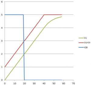
Ah, Captain, ye of no faith. Pay close attention to the noninverting input of IC5, a tricky little detail that I admit is easy to overlook. This "driver" IC maintains an output voltage that is a fixed increment (Vr) above the timing cap's voltage (Vc). That is, the driving voltage ramps too. The charging current is therefore a very constant Vr/R. It doesn't diminish as the voltage ramps upwards, so long as the driving voltage (Vc+Vr) doesn't clip. Here's how the circuit behaves: Vc = timing cap's voltage Vr = voltage driving the ramp. I've used 1V in this example IC8 = output of comparator (arbitrarily used TTL'ish voltages) When the timing cap charge is dumped, voltage goes to zero. The driver voltage then drops to 0 + Vr = 1V. Charging current is Vr/R. The driver voltage tracks Vc until it clips near the supply rail. I'm illustrating the clipping voltage at 5V in this example. I've arbitrarily set a threshold at 2V. When Vc reaches 2V, the comparator output goes low. It's admittedly a weird circuit, but it should yield a freakishly linear ramp, using much/most of the available range in supply voltage. Moreover, large changes in charging rate can be made without chewing up too much available supply voltage "overhead." Mind you, I haven't breadboarded the thing yet. (See why having this thing dance around my head -- at least ICs 5-7 -- left me sleepless last night?) EDIT: I did seem to neglect drawing the ground on the noninverting input of IC7 in my schematic. Sorry for that omission. So ICs5, 6, and 7 are a difference amp, a follower, and an inverting amp, respectively. Also it should go without saying that the conditioned correction signals circuits are just shorthand. I might also have to invert a signal or two, prior to the ramp generator.
-
Demented musings
-
-
Captain, I hadn't heard of an integrating ADC. I'm not sure it helps, but it's interesting. Anyway, now I can go to bed. I hope I won't be thinking about boating now, as I have to restring a couple of rotten halyards, and that's making me nervous. Maybe I can think about football. That would definitely put me to sleep!
-
Zed, I've also pondered transplanting a more modern EFI. I would think something using a MAF sensor would work, especially a system designed for a 6 cylinder engine. To your knowledge, has anyone done such a thing? I have to think correct mixtures are correct in any engine, but that may be a naiive notion.
-
HR, my '78's beautiful FI heart is the organ most in need of a transplant. The AFM is fine. The '78 ECUs (and also the '77 ECUs -- Hitachi redesigns of the original Bosch) seem to lean out over time. But still, clever thoughts about substituting an MAF sensor!
-
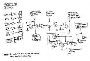
I hate it when these things bug me and keep me awake! The only solution is to jot down a circuit and get it out of my head. So here's what I had in mind -- a partial analog ECU: IC1 adds various conditioned sensor inputs, together with a target "stoichiometric" voltage for the wideband O2 sensor, to generate an output voltage corresponding to the desired air/fuel ratio. The pots adjust relative influence of each conditioned signal on the corrected mixture. This is compared against the output of a wideband O2 sensor (IC2), and the comparator output is smoothed to yield a correction voltage, which is followed by IC3. IC4 then subtracts this correction voltage from a baseline voltage, to yield a corrected voltage, Vr, used to set the ramp rate of the timing capacitor. The voltage ramp is driven by IC5, which outputs the sum of the timing cap voltage, Vc, and the ramp voltage, Vr. Thus the cap's charging rate is constant with Vr, and thus the ramp is perfectly linear. IC6 generates the voltage ramp output of the circuit. IC7 inverts this output to feed back into IC5. Q1 is used to dump the cap and re-initialize the voltage ramp. Finally, IC8 compares the ramp against a conditioned AFM signal, to create a square wave injector pulse. I didn't worry too much about signal polarity. Four quad op amps would do it. It's a bit Rube-Goldberg'ish, but so is the original ECU. BTW, this circuit would run closed-loop from the moment of startup and would use the broadband sensor to calibrate to the initial richer mixture. Is this even possible with a stone-cold sensor? I suppose the output of IC2 could be limited to some range that would "work." Hopefully the O2 sensor registers a lean condition when it's stone-cold. Any thoughts about that? (I understand it's a bad idea to pre-heat them before cranking the engine.) There! Now I can go to bed.
-