FastWoman
Community Member
-
Joined
-
Last visited
Everything posted by FastWoman
-
Argneist, you'll be able to see where all the hoses go after you do all your disassembly. You'll need to remove (almost?) all the plastic panels around the hatch area. That will reveal the fuel/air separator tank in the right rear quarterpanel, as well as the vent hoses that loop around the back and exit through the floor. Remove the separator tank, pulling off all the hoses. Then push the vent hoses through their respective holes in the floor of the hatch. Loosen and break loose the rubber filler neck. Remove the metal shield from the lower part of the right rear wheel well. Then unbolt the tank straps, and lower the tank down -- probably with some help from above to feed the filler neck through the hole. You'll be able to see and replace each and every hose.
-
Wow, I've never heard of that playing out! I'll never slip a hose in a gas tank again! Why not just pull the sending unit out to clear your tangle? It's a lot easier than dropping the tank. FAIW, the easiest way to drain your tank is to remove the plug at the bottom.
-
Seemed that way at the time!
-
Ah, geez! That happened to my mom in Laredo -- a nice late-model Cressida that she had entrusted to a valet parking garage. She never got it back. I hope you have better luck.
-
Oh yeah! I forgot too! OK, you're good. I think you've got the valves on your list (which is a satisfying, non-stressful thing, I promise). Put your best non-rebuilt AFM on, get your CTS screwed in, go to Radio Shack for parts, and you'll be good to go. Here, get these. You can even mail order them: http://www.radioshack.com/product/index.jsp?productId=2062308 http://www.radioshack.com/product/index.jsp?productId=2062758 Optionally: http://www.radioshack.com/product/index.jsp?productId=2062715 http://www.radioshack.com/product/index.jsp?productId=2049747 http://www.radioshack.com/product/index.jsp?productId=2104090&clickid=prod_cs Watch this (or any number of other videos): While you're at it, also order this, so that you can test the potentiometer in your AFM: http://www.radioshack.com/product/index.jsp?productId=2999093# The reason you need a needle is that you can see it twitch if you have a dirty electrical contact. You can't see a digital display twitch. Let's get your car running!
-
Zed, all the resistive material laid down on the potentiometer board should be the exact same stuff. If it all changes resistive properties the same, then all the resistances would change by the same proportion (including the carbon trace that the wiper glides along). Therefore the voltages relationships should remain the same.
-
Period correct for an aftermarket wheel? This probably would have been the most ubiquitous '70's era style of aftermarket wheels: http://www.newstalgiawheel.com/wheel_detail.asp?subcat3=1071101 or... http://www.newstalgiawheel.com/wheel_detail.asp?subcat3=1111101 Then this: http://www.newstalgiawheel.com/wheel_detail.asp?subcat3=1011118 Hurricane mags were really popular too: http://www.akhwheels.com/pages/showWheel.php?pk=408 I had some like this on a '75 in the early '80's: http://www.newstalgiawheel.com/wheel_detail.asp?subcat3=1011115 It was unconventional, but it looked great.
-
Oh, and perhaps I didn't answer the question you were really asking: The ratio of these resistances is almost spot-on identical -- .5555555 vs. .5575221. That's identical in automotive terms. As for failure modes -- perhaps the carbon traces absorb moisture and loose their compactness as they expand and contract over the decades. That would drive resistance up. But again, it's no problem if all the carbon traces are drifting towards higher resistance in the same way. The voltage ratios will remain the same. I'm sure the Bosch and Hitachi engineers designed the various components with this dynamic in mind. (I certainly would have done that myself.)
-
Honestly, when you're talking about fuel and air in a cavity, going bang, I think there's some room for error. You might find this hard to believe, but I was even able to start my engine without the AFM plugged in (forgot to plug it in!). It blew black smoke out the exhaust, but it still managed to keep running. As I've said before, I think my car was delivering about 25% less fuel than it should have, when my local Z specialist declared that my engine ran pretty nicely. The PO felt the engine ran nicely when it ran even leaner than that. I didn't completely agree, but I thought it was reasonably driveable (enough to drive it a few hundred miles home), and I felt it had the potential of becoming a good engine (which it did). So there's considerable margin for error, IMO.
-
No worries, Jenny. You have every reason to be frustrated right now. These old cars can get pretty funky, and they stay funky until you find all the problems. I think the best perspective to have is to keep tinkering, be happy when it runs, be thrilled with any improvements along the way, and keep tinkering. Eventually your car will be right again. You know.... Eric might disagree with me about this, but I suppose an argument could be made that you DON'T have to have everything perfect before making the mixture adjustments that we've been recommending. This frustrating process has been a bit like Master-san training young Grasshopper mechanic, starting with wipe on, wipe off. Maybe the more sane approach (that will keep your spirits up) is to fix everthing you see that obviously needs fixing, leave unknown stuff for the future, install a variable resistor in your coolant temp sensor circuit to adjust your mixture, and enjoy your car. Then whenever you discover and fix a new problem that might alter your mixture, simply readjust your mixture. Contemplate this procedure: 1) Get a 5 kOhm variable resistor from Radio Shack. Set it to roughly 2.5 kOhms Attach two wires to it, and plug those wires into the CTS connector (the harness side). 2) Start your engine. Adjust the variable resistor for the smoothest idle. 3) As your engine continues to warm up, keep adjusting the variable resistor to maintain a smooth idle. 4) When the engine is fully warmed up, do a very careful adjustment of the variable resistor to achieve the highest engine vacuum. Then shut your engine down. 5) Measure the resistance of the variable resistor, and measure the resistance of the CTS. Calculate the difference. 6) Report back, and I'll help you figure out what resistance to wire where, in order to achieve a good idle. 7) Wire in your extra resistance, and give your car a test drive. You can adjust the resistance a bit, if necessary, to fine tune it. 8) Love Cars, Love People, Love Life. Enjoy the ride.
-
@Venus (Karen): An RX-7 in the attic?! I'm impressed and humbled!
-
Zed, 100/180 and 126/226 are roughly the same ratio (=.56), hence the voltages would be the same. It's possible that that these resistances all drift the same way over time with heat and oxidation. If the resistive material all ages uniformly, the resistance ratios would stay the same, and hence the voltages would remain the same. With regard to 25% being a large error: Well, yes, it would be significant if resistance were what is important. However, if we're talking about the ratio of voltages U/Ub (per what the FSM says), then the errors would be inconsequential.
-
If you drain the tank THOROUGHLY, blot up any remaining pool of gas with a paper towel taped to the end of a stick, and let the tank bake in the sun with the filler neck pointed down and the sending unit removed, the gas will be gone before you know it. (Might have to wait for warmer weather, though.) Use your nose. And as always: Try this at your own risk. I'm an idiot, and you shouldn't be taking my advice. So you're warned!
-
[broken record] It's the voltages that matter, not the resistances. In fact it's possible that different versions of the AFM have different resistances but the same output voltages. I don't think your old AFMs are necessarily bad. (I haven't seen any evidence either way.) Also I doubt your rebuilt AFM is bad. [/broken record] The FSM's diagnostic criteria for the AFM do not specify tolerance limits for their resistance measurements, beyond which the unit would be rejected. This is in sharp contrast to items such as the CTS, which have rejection limits specified. I think these measurements are therefore approximate, and the resistances given in the FSM are only guidelines. If you read 500 ohms when you should be reading 100, then you might have a problem. However, 125 and 100 are perhaps close enough to verify that the resistor is largely intact, which might be all that's necessary. Remember that tight resistive tolerances are a more modern thing. Back in those days, the typical carbon resistor had a 10% tolerance specification. CTS: You might be able to sand down the CTS connector to fit inside a deep socket. There's probably no harm in that. Be careful that you're not torquing the connector, rather than the base, when you screw the thing in. FAIW, you might be able to fit a crow's foot wrench around the base. You don't have to turn the thing very hard to get a good seal. A general word of advice from the BTDT (been there, done that) camp: You might not be in the right frame of mind to work on your car right now. When you're frustrated and angry, it's time to set the wrenches down, before either you or your car gets hurt. ------------------- Zed, I think I might know why our pennies vs. voltages measurements are somewhat different. I used pennies collected in a jar by an elderly gentleman. His might be older than yours. If so, they would have a higher copper content, while yours would be mostly copper-clad zinc (lighter). Perhaps we need a different standard than coinage. Either that, or the pennies must first be sorted by date!
-
Jenny, I think that rusty bolt with the washers and the one opposite it secure the thermostat housing to the cylinder head. As you deduced, the washers are there because the bolt is too long. The hazard of having that rusty bolt insert too far is that it will actually push on the back of the timing chain guide and bend it, causing problems you don't even want to think about. You can see the backside of this threaded hole if you remove your valve cover. If I were you, I'd first remove the thermostat housing cover via the two bolts on top and then the thermostat housing via the two bolts on the side. then you can replace the sensor and put everything back. The reason I recommend taking all this apart is that it will be corroded. The longer it corrodes, the harder the bolts will be to remove. The bolts probably need freshening, and the threaded holes should be chased out with a tap. (Note, watch the aforementioned threaded hole very carefully with the valve cover removed as you chase the threads out, so that you don't damage the timing chain guide.) This is also a great opportunity to get a fresh gasket between the thermo housing and head. Seepage there can cause you big headaches later. Be careful, because of the corrosion. Use lots of PBlaster. Reassemble with plenty of antisieze. Check my "purs like a kitten" thread for a recommendation by ZTrain to place studs in the thermo housing for the cover. I did that, and it worked great. If your bolts don't turn with reasonable force, don't get heroic. It might not be worth the fight (and the broken bolts). Just go for the coolant temp sensor by itself. It will be hard to access, but it probably won't be screwed in too tight.
-
I'm not saying this guy isn't a scammer. He obviously is. However, I'm just curious how the scam works with PayPal. Is it that PayPal will refund the funds to the scammer somehow through a buyer protection claim? Or is it that a fake PayPal receipt of payment email will be dispatched? I understand the cashier's check scam, but this would have to work differently. FAIW, part of the scam is the harvesting of email addresses. When you advertise on CL, your address isn't shown. Someone emails you to ask whether "the item" is still for sale. You reply from your legitimate email address that the item is still for sale. Then they have your email address and will sell it to spammers. The best way to advertise on CL is to put your phone number at the bottom and check the box that says not to allow email responses. I've sold a number of things through CL, and I've never received an illegitimate call. Scammers don't call.
-
Sure. Seems reasonable. If you get hard into negotiations, offer to throw in a good camera.
-
Maybe your S terminal (voltage reference) isn't correctly wired or has a faulty contact??? Dunno.
-
Very nice! I like it more than the Leaf.
-
Cool! Please remit 10% of the money you saved to my email address via PayPal. Nah... Just happy it worked out for you.
-
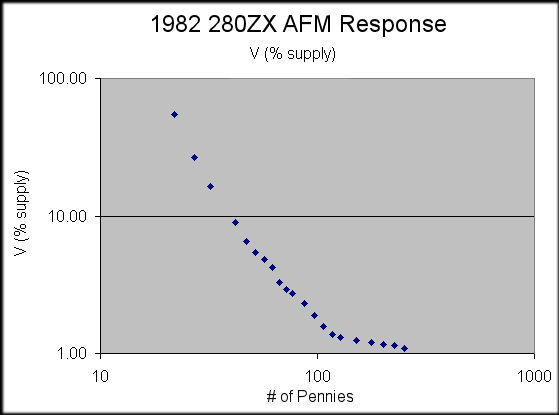
Hey Zed, No, I didn't change the tilt. There's not any significant dragging of the string, at least in an '82 AFM. I do note some minor differences in relation to the '78 -- no backfire relief valve, a slightly different stop for the vane (full closed), and a somewhat different configuration of air bypass, with two idle mix adjustment screws, rather than the one. Anyway, yes, there's definitely a leverage issue. I considered tilting the meter but thought it would be better to aim for easy repeatability, hence the huge pile of pennies. Yes, I do have a centigram electronic scale. The average weight of 3 quarters is 5.66g (each). Therefore 28 quarters would be approx 158 g -- roughly equivalent to 62 pennies, yielding 4.24% of the supply voltage, vs. your 5.1%. (All things considered, that's actually pretty close. Remember that my vane drags/sticks just a bit.) I get 41 pennies at mid-vane, not 62 (not counting the 2 pennies worth of weight in the paper). I'm considering mid-vane to be the point at which the wiper is evenly aligned with the silver contact arm. Do you get 22 pennies to just start opening the vane? I think that might be the source of the differences in our measurements. FAIW, the Atlantic Z beer can method is based on measurements from a '76Z and an '80ZX. My '82ZX looks just like the '80ZX pictured in the writeup. According to the author, the spring tensions are the same. Perhaps my AFM is off. Mine seems not to have been readjusted, but the cover was conspicuously loose when I got it. I don't know its history or how well it works on an actual engine. All I know is that I got it cheap.
-
Jenny, the problem is that all this info is proprietary and therefore reverse-engineered, just like we're doing here. You're not going to be able to see underneath your intake well enough to find leaks. Honestly, my yogurt cup test is the way to go. It's VERY fast and easy. It will take you no more than 5 min after you've got your AFM off. If you've got afterfire, then it does sound like you're running rich. That wouldn't be a vacuum leak issue. You should check the CTS resistance at the ECU plug to make certain you don't have a bad connection or corroded wire somewhere. You might have a broken solder joint in the ECU. You might try picking up a spare on Ebay to try out. ZTrain had this problem and fixed his ECU by re-flowing the internal solder joints. That's just the process of melting all the solder connections, one by one, with a soldering iron. It's a bit tedious, but it might pay off for you. Another problem spot could be the cold start valve. Mine was stuck partially open, thus enriching my mixture. Obviously also check the thermotime switch. Dinner!
-
Obviously I had some slightly sticky flap issues. Perhaps I should have hosed the working parts down with WD-40 first. I did try to shake the AFM a bit before each measurement to get the vane position to stabilize.
-
My '82 AFM's terminals are labeled a bit differently. I belive my 8-9 measurement would be 129 ohms, and my 6-9 would be 357 ohms. The difference (6-8) would be 228 ohms. I measure 231 ohms. Close enough. (So my '82 AFM's resistances are similar to yours, Jenny. I've never had it in a running car, so I don't know how it operates.) Pennies vs. Voltages: pennies V (% supply) grams 22 54.79 56 27 26.67 69 32 16.36 82 42 8.97 108 47 6.55 120 52 5.45 133 57 4.85 146 62 4.24 159 67 3.27 172 72 2.91 184 77 2.74 197 87 2.30 223 97 1.89 248 107 1.58 274 117 1.37 300 127 1.30 325 152 1.25 389 177 1.20 453 202 1.16 517 227 1.14 581 252 1.09 645
-
BTW, there is no way on this '82 AFM to adjust the spring constant. The ends of the clock spring seem to be molded into the plastic parts.