


Pomorza
Free Member
-
Joined
-
Last visited
-
I'm just going off what here. They call it an ECU. My FSM calls it a "control unit". Either way, the analog wizardry box that makes the engine go vroom.
-
@SteveJ Thank you sir!
-
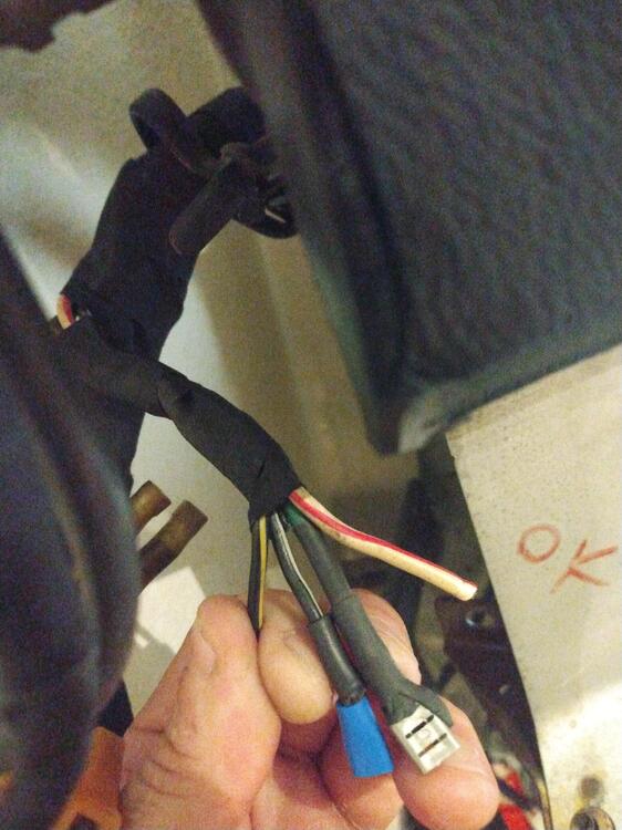
Hi gents I'm redoing the wiring harness in my Z and hope someone could help. I've come across these wires - which used to connect to the ECU. Here's what I know Green -> goes to the fuel pump Red/White -> 12V from the battery The two that I don't know are the black/white and black/yellow. From this diagram it looks like the black/yellow goes to the ignition switch among other place and the white goes to the ignition relay and the "IG" part of the fuse box. So would these be 12V switched? I am a bit confused. I've attached photos of the wires themselves as well as the part of the diagram where they are. Any help would be wonderful! Thank you Jan

-
I'm trying to figure out if this system will fit my Z. Its a 76' with the stock intake manifold. Everything I've read - from the supply side - states that these are for triple carb setups and am wondering if anyone has tried doing it on the EFI cars.
-
If the header will work with the stock 280z intake manifold.
-
Anyone know if this system will work on EFI manifolds?
-
Thank you sir! I'll keep yall updated
-
What about the red/blue to the hazard lights? Doesn't that need to be connected some way?
-
Based on the diagram I'm looking at this is what I see: (this diagram) Red/Blue goes from the dimmer to the hazard switch. Green/White goes to the combination switch. Using your previous example I figured another relay would look like this. Green/White -> 86 & 87 Red/Blue -> 85 Dash lights -> 30. I'm 100% sure on that but it makes sense to me. Would you agree? I figured the lights were driven off power and ground but clearly I was wrong. Cheers Jan
-
Steve. I bought some 6.3mm connectors for this job last year so connector wise I'm ready to go. I do plan on depinning all the pins/wires I don't use and pulling them out of the harness. As for the LED head lights, I've been running H4 headlights since I bought the car in 2009. I will add headlight relays since I already have the harness out of the car. For the backlight on the gauge (single white wire). Does this also have to go through a relay with the wht/grn + red/blue wire or can I just by pass the dimmer? Cheers Jan
-
I was worried that this would require more than just plug and play. Simple enough though, I was planning on adding relays to the headlights anyway. Just to make sure I have everything correct here. From the Speedhut schematic 1. Red (pwr) -> Green power wire on Z car (12V) 2. Black (gnd) -> black on z car (ground) 3. White (lights) -> green/white on Z car (dash lights)* 4. Blue (high beam) -> pin 30 on said relay 5. Green/orange (RTS) -> white/black on Z car (12v turn sign right) 6. green/red (LTS) -> white/red Z car(12v turn sig. left) *Or do the dash lights also have to go through a relay since there are two wires. I don't plan on using the dimmer (was actually planning on removing it all together). All the other gauges are just three wire + sensors which I can figure out pretty easily. Thank you for all the help! Cheers Jan
-
Speed hut Z series. The speedometer has both the high beam indicator (one wire) and the turn signals (one wire each).
-
Steve. Thank you sir. How would I go about wiring the high beam indicator on my new gauge if its only one wire - should I just put the red + red/white together? Cheers Jan
-
Hello everyone At the beginning of November I started the restoration of my 76' 280z. The body is currently getting fixed and painted, engine is being rebuilt and I took on the task of rewiring the dash for the new gauges. My plan is to use the wires required from the original dash harness while getting rid of the ones I don't. Here is where the problem(s) start. I have a FSM and a colored wiring diagram but to be honest I'm having a hard time figuring out what wire does what. I started with the speedometer, which in the FSM states has 7 wires (one spare pin). Mine has all eight used. The connector pins out as follows: The connector is as follows: Red Red/white Green/white Green/yellow Red/Blue Black Green Green/red I know that the green/white and red/blue are the dash lights - not sure which one is power and which one is ground - and black is ground. I'm also almost positive that the red is your 12V switched from the fuse panel. All the other ones I'm at a loss for. Could someone chime and help? Thank you Jan
-
Hi guys! In the near future I will be rebuilding my Z engine and plan on replacing the N47 head that's on it with a N42 I purchase years ago. The issue is that the cam on the N42 is, well rusted and pitted. I was looking at getting the Cam kit that MSA sells (the Schneider Cam) that comes with everything. Has anyone else used these? Or are there better options? If Im replacing the cam I figured I would need new rockets and lash pads no? Thanks mate Cheers Jan


