Zed Head
Free Member
-
Joined
-
Last visited
Everything posted by Zed Head
-
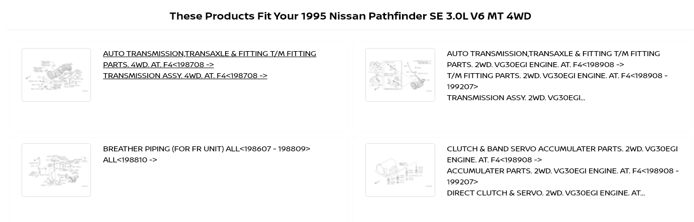
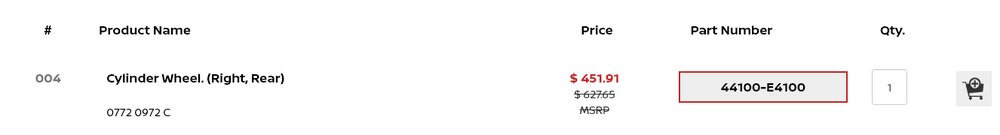
 Cool! The platform looks great but I assume that it can only show things according to how the people using it put in the data. It needs some work. They're showing AT parts on the MT page. I doubt that they fit... (I had a 95 Pathfinder).
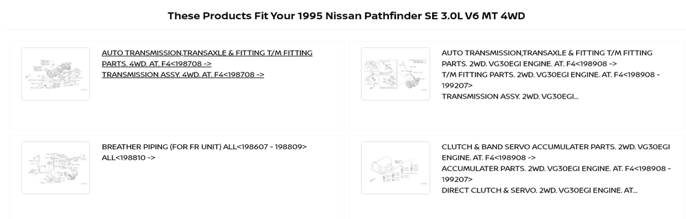
-
Holey-moley.
-
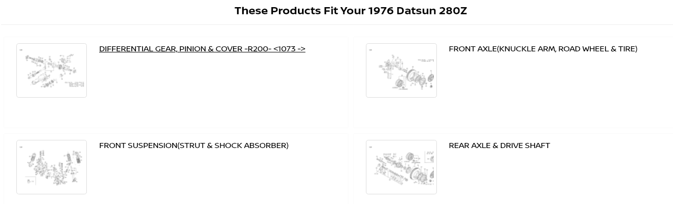
The guys at the original Courtesy said that they were working on an improved site. Looks like they finally got it done. It looks very nice. You can go directly to your vehicle and find parts. It's better than MSA's wb site. Very well done.


-
This popped up this morning. I've noticed that there aren't many Datsuns ending up in the local wrecking yards anymore. This one looks like it might still have the drive train. The whole car might even be saveable! https://row52.com/Vehicle/Index/JN1HZ04S3BX405996

-
Another option is a local off-road shop. The ones that support the guys that destroy things every weekend. Or one of the big online shops. https://www.randysworldwide.com/shop/?q=shims&mode=autocomplete
-
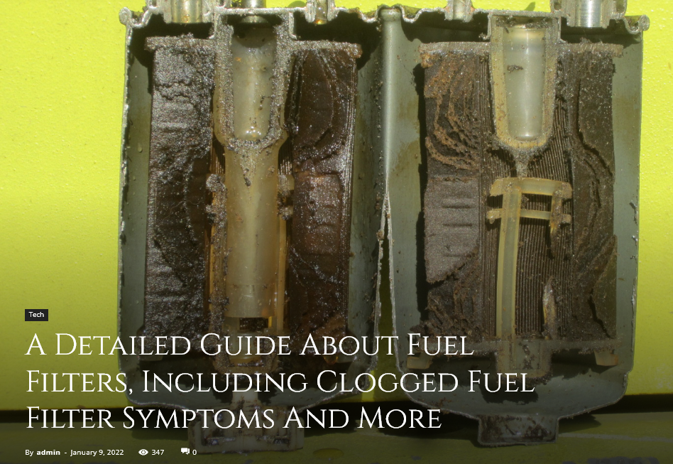
On the half-full filter issue - it might be that the exit point is not where people think it is. Has anyone taken one apart? https://writina.com/clogged-fuel-filters/
-
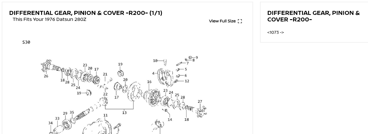
Does the ring gear move freely without holding the pinion flange? Might be that things got so hot that a carrier bearing race walked outward. That would tighten up the lash as the bearings are tapered roller bearings. Onw trick for installing new carrier bearings is to put them in the oven and drop them over the nose/mount/whatever while they're hot, instead of pressing them on. Since you have it out you might as well remove the carrier and see if those bearings are fully seated. You can reseat them with a drift/punch on the race.
-
By the way, not an expert, but I don't think that spider gear lash matters much. You want to put your indicator on a ring gear tooth and move the ring gear back and forth to see how much lash there is between it and the pinion gear. . . .
-
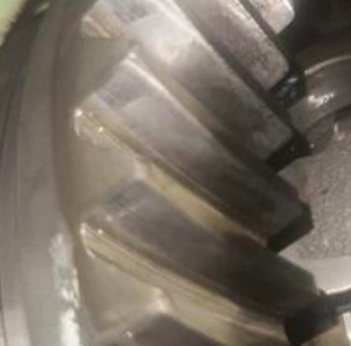
Could be bearings or it could be gears. The pattern on the teeth looks good, but probably shouldn't be seen so easily. Looks like wear, you might take a really close look at individual teeth faces. If that's where the noise is coming from then you might need to move the OEM gears over to the CLSD carrier and give it a full rebuild. Regardless I think that the CLSD portion is probably fine. Differentials can survive and function with some pretty bad looking gears. If it's not too noisy with a full oil level, maybe just drive it and see what happens.
-
One of the commenters used the Hagerty Insurance Valuation Tool. It was just a puzzle I wanted to solve. I think the buyer contacted the seller, asked what the reserve was, and set his starting bid there. Nobody else was interested at that level. They had nine days to ponder. The buyer's tastes seem undiscernible. A 1934 Packard Sedan and a 1971 Nissan sports car don't have much in common. I'll be following just to see what's next on his list. BAT is good entertainment.

-
Somebody might have mentioned this above or in the auction comments, but it seems likely that the bidder knew what the reserve price was and decided that he wanted the car at that price. Or higher. So, kind of like eBay's "Buy it now" price. The reserve price was too high for everyone interested except one. One of the commenters mentioned a Ferrari auction. It seemed more normal. https://bringatrailer.com/listing/1998-ferrari-550-maranello-9-2/#comments-anchor
-
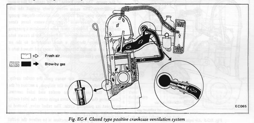
Is that from a Chilton or Haynes manual? You can get the Datsun manual from this forum's Download area. Linked it at the end. That's your PCV system. The big hose nipple connects to the little one. You can find them on eBay or somebody on the forum might have one. Here's an example. https://zcardepot.com/products/crankcase-pcv-vent-hose-oem-70-74 If you leave them open the top one will cause carburetion problems and the bottom one will blow oil vapors all over your engine bay. https://www.classiczcars.com/files/
-
Got curious and searched the Bosch number. Doesn't seem to be what you're looking for. https://www.niparts.com/MAC/69BB43/BOSCH/0280230009.html

-
The competitive aspect of the auction is designed to determine "market" value. There was no competition here. If the guy put it back on the market would he get $130,000 or 250,000? That's a pretty big spread. If you guys want to show a sampling of Z432 prices over the years that would be more substantive than a Hagerty appraisal. Estimates from afficianados don't really have much weight behind them. It's like bench-racing. But the price paid is not my point anyway. The method of getting there is. Could be the guy read a Hagerty article and accepted their estimate and assumed that there would be competition. Who knows. It's interesting.
-
You're doing it again. I did not express amazement. I expressed bemusement at the guy's bidding. Read>comprehend>respond, if necessary.. I see several BaT's comments saying that because the guy paid it, it must be the correct market value. That's nonsense.
-
Making a high bid early shouldn't discourage anyone who "knows" the market. Anyone who can bid 1/4 million dollars can surely pay to ship the car to Japan. The premium market. I could see bumping it up in 10's to show your determination. But 120 is not rational, unless the purpose is to be able to say that you own a $250,000 car. Or a guy who just didn't know what he was doing. There's no way to explain away the oddness. The other guy I mentioned actually responded on the BaT page and said that he bid way over the last bid because he thought that was the car's value and he wanted to pay it. But one-person value is not market value. In terms relative to the whole market it's just one guy who "over-paid". It will be interesting to see if it pops up somewhere. The guy owns an old Packard also. His bidding made more sense on that car. https://bringatrailer.com/listing/1934-packard-twelve-1107-club-sedan/

-
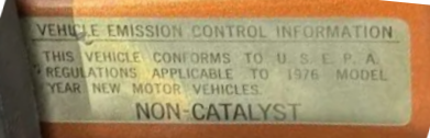
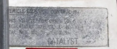
By the way, I think that if the car is a Federal model it won't have the sensor because it won't have the catalytic converter. If the car is a California model the label on the door jamb will say "CATALYST". If it's Federal it will say "NON-CATALYST". Not sure if they left the sub-harness in anyway if it doesn't have a converter.
-
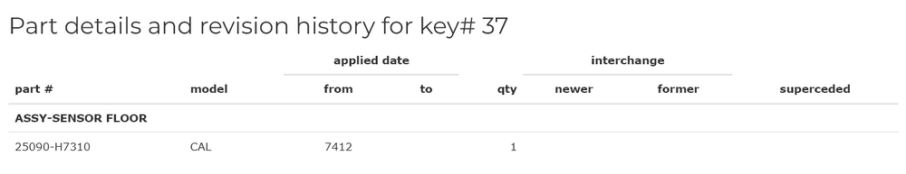
I found what seems to be the part number but can't find it in the drawing. Might be that the Bosch part has the same function. Seems like it would have a bimetallic strip inside that moves as temperature changes. If there's no strip it's probably the wrong part. https://www.carpartsmanual.com/datsun/Z-1969-1978/electrical/electric-unit-switch/section-2/280z/37
-
Regardless of thoughts on value, it's just not rational to bid like that. If money has value to you. It would be ironic for somebody who has $250,000 of extra income to not understand how to maximize the value of his money. Unless he has so much money that $250,000 is a drop in the bucket. Or he made money the easy way, by investing in something like crypto and it's just a number on a computer screen. I know some crypto people and they have tons of money and really have not worked very hard for it. We live in strange times. Maybe the buyer expected some competition. Or maybe he believed what the internet says is the "correct value" of the car. Whatever is going on, he probably could have saved 10's of thousands of dollars by bidding in a rational way. It's just weird is what I'm saying.
-
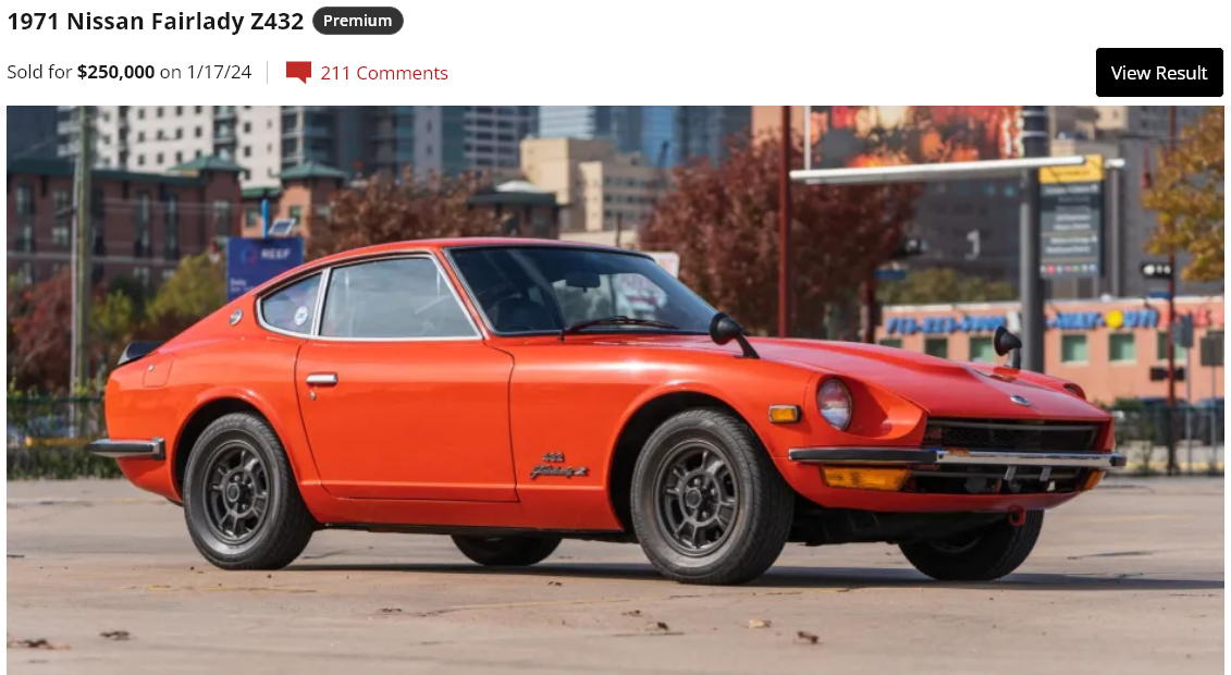
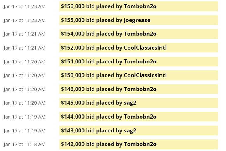
Another weird auction. There was one in the past where the guy made a huge bid, way over the last, and ended up getting the car. The guy that got this Z432 bumped the bid by $120,000 nine days ago. And won. Weird stuff. Not how auctions typically work. Money to burn. https://bringatrailer.com/listing/1971-nissan-fairlady-z-432/

-
There is a lot of downloadable stuff on the site. https://www.classiczcars.com/files/ https://www.classiczcars.com/files/category/1-wiring-diagrams/
-
Interesting that the Yves folks didn't set a reserve above the selling price. Maybe they just wanted to move it on. Based on past BaT results the 199 number should have brought more. Maybe the low number obsession is waning.
-
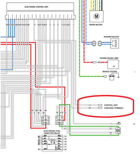
They just hang there. "Checking" terminals.
-
Only 30+ pictures, no driving video, no discussion. More about the resto shop. https://www.mecum.com/articles/st-yves-datsun-nissan-collection/
-
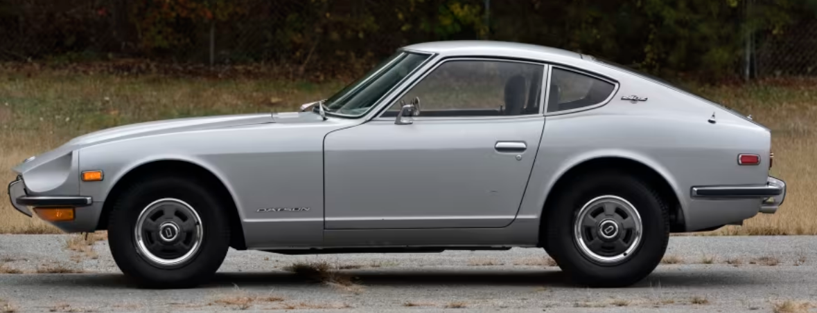
Mecum seems more like a muscle car nostalgia crowd. They should have put it on BaT. It a low miles low number car. Very clean looking, click the link. #199. It's even been restored by what looks like a pro shop. ODOMETER READS† 64,609 miles VIN / SERIAL HLS3000199 HIGHLIGHTS Early production car built in late 1969 (11/1969) Part of the St Yves Collection since 1981 Older 1980s restoration by St. Yves Motor Sales, with attention to factory details and specifications, using OEM parts when available Restored in original 901 Silver Original matching numbers DOHC 2.4L inline 6-cylinder engine 4-speed manual transmission Dual "round-top" SU carburetors Under hood work light Chrome bumpers with front and rear bumperettes