Zed Head
Free Member
-
Joined
-
Last visited
Everything posted by Zed Head
-

 Downloaded MSD 6A and 6AL ignition system instructions from Holley's web site. Hope it's not a problem.Free
 -
This occurred to me - a GM HEI module should work as a voltage increaser. It's odd that MSD's "12 volt square wave" is not 12 volts. But, you should be able to use an inexpensive HEI module as a pseudo amplifier. Connect some small load to B and C of the module, like a light or a resistor, with a branch off to the tachometer wire, and G and W to the MSD tach output wire. The G-W circuit will be the trigger, triggered by the MSD wire, to cause the module to pass the 12 volts to the light bulb or resistor, operating the tach through the branch. Basically the MSD tach wire acts like the reluctor trigger and the light bulb acts like the coil, and the branch off to the tach is the standard tach driver wire. Only commenting while it's in my head. Something to consider if you get stuck.
-
Here's the MSD stuff. I've always wondered about the voltage sensing tachs. Do they just see the voltage appearing and disappearing as the coil circuit is made and broken? Or do they need the big "flyback" spike from the coil discharge? https://documents.holley.com/6425.pdf TACHOMETERS The MSD Ignition features a Gray Tach Output wire that provides a trigger signal for tachometers, a shift light or other add-on rpm activated devices. The Tach Output wire produces a 12 volt square wave signal with a 20% duty cycle. Some vehicles with factory tachometers may require a Tach Adapter to operate with the MSD. For more information on Tachometers and MSD Tach Adapters, see the Tachometer Section on page 6. If your GM vehicle has an in-line filter it may cause the tach to drop to zero on acceleration. If this occurs, bypass the filter. INOPERATIVE TACHOMETERS If your tachometer fails to operate with the MSD installed you may need an MSD Tach Adapter. Before getting an Adapter, try connecting your tachometer trigger wire to the Gray tach wire of the MSD. This output produces a 12 volt, square wave (see page 2). If the tach still does not operate, you will need a Tach Adapter. There are two Tach Adapters:
-
I wonder how the tach wire on the MSD box works. That's where the voltage is coming from that is then either amplified or is used to trigger the Technoverion unit. "generates a stronger signal". I went back and found the instruction manual by accident. Here's some text. Click on Voltage Boost on the sidebar in the link and it will take you down to the instruction manual. Haven't opened it yet. So exciting!!! https://www.technoversions.com/documents/TachMatchVBoostInstructionManualRev-.pdf https://www.technoversions.com/TachMatch.html#TM4 TACHMATCH VOLTAGE BOOST MODULE Most tachometers can be driven with a 12v pulse signal, such as that provided by the standard TachMatch and the MSD-6 series. However, some tachometers need a stronger signal that more closely replicates the signal generated by the coil. The TachMatch V-Boost Module takes a lower level input signal, whether it be ECU output, MSD 6 tach output, or from a standard TachMatch TM-03, and generates a stronger signal to the tachometer, similar in function to the MSD 8920. Another application is when you are changing from a coil-style ignition to a system that uses a ECU. Often, ECU's, with a 5-volt signal, will not drive tachometers designed to use a 12-volt (or higher) level signal. This unit will convert from the digital-level signal to one which will drive your tachometer, similar to the Auto Meter 9117. The TachMatch Voltage Boost Module does not do cylinder conversion. If you need that, it needs to be driven from a TachMatch TM-03. Details of it's connection can be found in the instruction manual below.
-
That's not where I end up. My general feeling is "don't mess with the AFM".
-
Where do resistors come into the picture with the voltage booster? The pull-up resistor? Are there instructions that came with the unit? Might help to take a picture and post them. I don't see anything on the web site, except the FAQ's. Probably want to tell which MSD wire you're using also. https://www.technoversions.com/TachMatch.html https://www.technoversions.com/Faq.html
-
The AFM vane is controlled by a spring. So you have to get in to how the force curve changes as you loosen or tighten the spring. For example, if you loosen the spring, the vane will move faster at low air flow, than at high air flow. I think, my memory of spring rates and how to work with them is fuzzy. And I don't know if a clock spring (which is what you'd call the AFM spring, I believe) is a variable rate spring or constant. It's probably out on the internet somewhere. Maybe even in an old paper book. Plus there is some preload. Some things can just be logic'ed out though. The ECU might behave as it would when the AFM is maxed out at mid-range air flow rates if the spring is loosened enough to let the vane move to its limit, even though the air flow rate is still changing, because the spring is not hindering vane movement as much. So you'd end up rich at low air flow and lean at high air flow. Because the AFM signal to the ECU has stopped changing. Or, if you tighten the spring the AFM vane might not move at all at low air flow rates. So you'd be lean at low air flow for a certain spread of air flow rate, then still lean as more air passed by but did not move the vane. Basically you change the slope of the curve. The resistor slides the whole curve over, AFM adjustment changes the slope of the curve and can create artificial limits. The ECU and AFM and injectors and sensors are all finely balanced to work together.
-
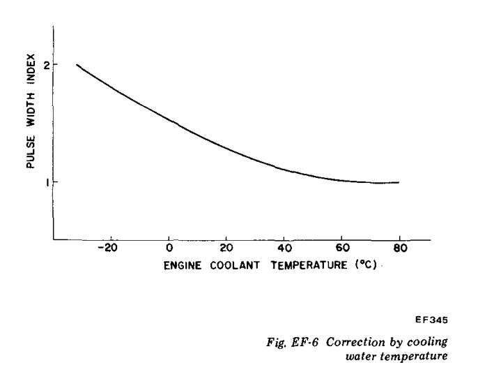
It's just a way to richen the mixture across the whole temperature range, and air flow range. It's a constant. Edited - I'm not sure that the actual curve is as flat at the end as Nissan shows it. Maybe it is though and with added resistance the ECU never sees a fully warmed up engine. The whole curve will get shifted to the right.
-
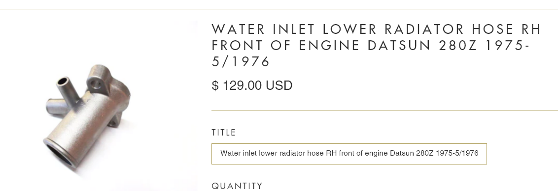
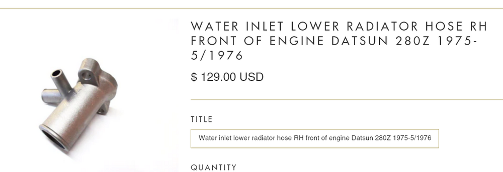
Looks like they were only used for a short time period. https://jdm-car-parts.com/products/water-inlet-lower-radiator-hose-rh-front-of-engine-datsun-280z-1975-5-1976?variant=27526042633
-
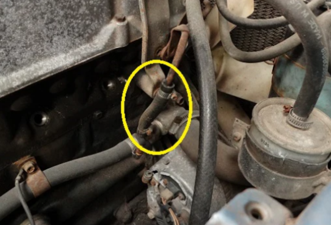
I think that might be the purpose. Not clear how many 280Z's or 260Z's or 240Z's had it or why nissan stopped using it. I've seen it discussed before thoguh. ZCD sells them and some people put a T in the return hose from the heater core. https://zcardepot.com/products/coolant-hose-engine-bay-t-fitting-280z-280zx Here's a good place to browse if you want to see what things are supposed to look like. Sounds like you have an aftermarket AC system. https://bringatrailer.com/listing/1975-datsun-280z-22-13/

-
Your post seems to have flipped the cause and effect relationship. Coolant temperature affects sensor resistance. But sensor resistance does not affect coolant temperature.
-
The 1976 FSM has a complete and separate chapter dedicated to the AC system. The 1975 FSM does not appear to have it. Probably worthwhile to download the 1976 manual and take a look.
-
A picture of the AC compressor would probably tell something. And the throttle linkage. The factory setup has a vacuum controlled idle speed enhancer for when the compressor is loading the engine. The AC condenser in front of the radiator would also be a clue.
-
In the early days he was just a guy trying to start a business. It was small. Unfortunately for many small business owners they often try to get big and take on debt that has to the repaid. Give him a chance to respond. He used to be active on the site. You can find his name and comments in past posts. @zcardepot.com
-
Here's an old interesting thread about the Euro turbo. Apparently not widespread. Made for the "Autobonds". https://www.zcar.com/threads/euro-280zx-turbo.309088/
-
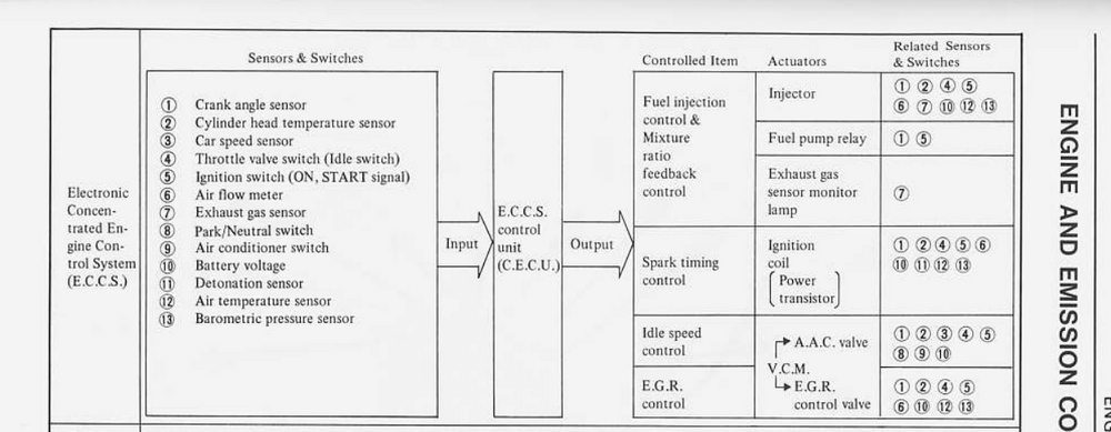
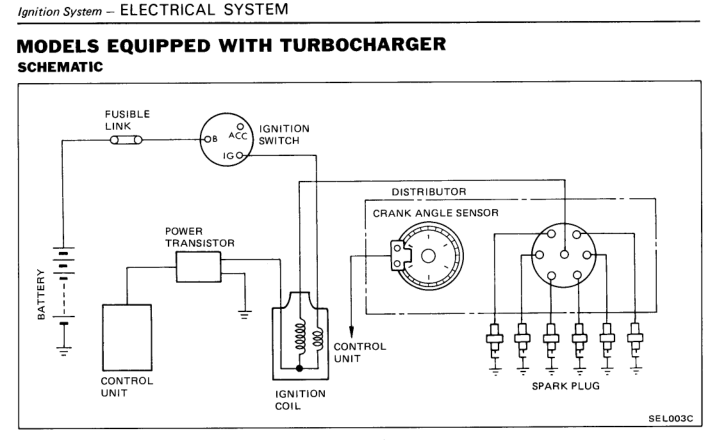
That's a 35 pin NA connector on a United States car. Maybe the ECCS system was only introduced for emissions purposes in the States. I don't see how ignition timing control would work though, since the ECCS controls that using the CAS in the distributor. Any chance that your friend has made the not uncommon mistake of confusing the injector cooling fan with a turbocharger? Maybe it's not a turbo car.

-
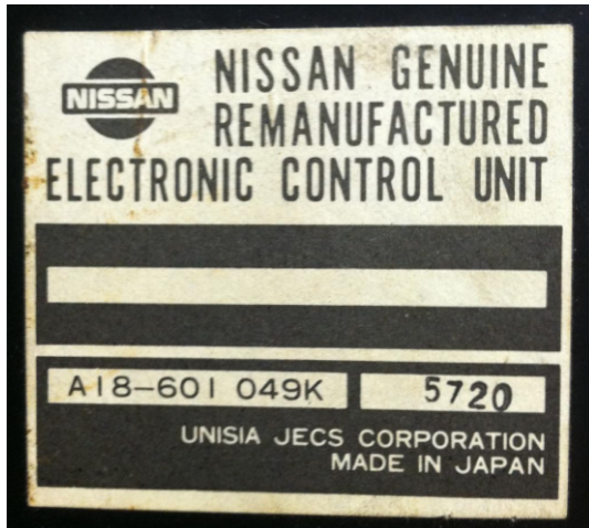
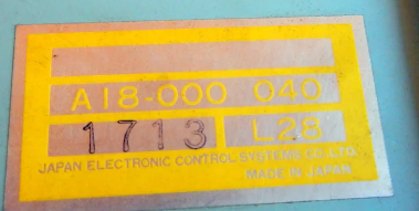
Will not fit or will not work? Check the FSM wiring diagrams. Get some part numbers. https://www.zdriver.com/forums/fs-240z-260z-280z-280zx-70-83-242/82-280zx-turbo-ecu-nissan-remanufactured-unit-35890/ https://maseraticompound.com/products/datsun-280zx-turbo-engine-ecu https://jdm-car-parts.com/products/ecu-for-datsun-280zx-turbo-nos?variant=744994189
-
I see a company in Florida. Not CA Datsun.


-
Motorsport Auto has a good selection. Probably cheaper and of higher quality. The Classic mirrors are actually 60's Mustang mirrors. I had a set. They fit well and I liked the look but they were noisy in the wind. You could hear them with the window open. One of those things that you don't really think about. https://www.thezstore.com/product/926/classic-chrome-mirror https://www.thezstore.com/isearch3?searchterm=mirror
-
That is a cool tool. No more fiddling around with two different gauges. This thread has the spectrum from cold adjustment, take-your-time and get it right, up to hot, I-know-what-I'm doing get it done.
-
The low clearance could be because the valve seats have worn. Maybe due to unleaded fuel on old seat material. People use brute force on the locking nut with a wrench and suffer busted/cut knuckles. The parts up there are sharp. I found that a small sledge hammer, like a 3 lber, used to tap on an open end wrench on the lock nut worked well for loosening. There's room for an open wrench on all of the locknuts, you don't need the crow's foot adapter unless you want to get precise on tightening torque. It's about as simple as it looks. There's a threaded stud with a locknut. Loosen the locknut, turn the stud, tighten the locknut, confirm lash. After a few you'll realize that tightening the locknut pulls the stud up and reduces clearance a little bit. There's a tutorial out there somewhere with pictures. Can't remember the name, it might actually be linked in this thread somewhere.
-
I used a vise, a socket, some fixturing, and a MAPP torch. I've always been surprised at how much effect heat has. Apply force, nothing, apply heat, movement, let cool, nothing, re-apply heat, keep going. It's been the same on broken off studs. And differential fill plugs. Heat is your friend. Even on the mustache bar bushings you can get the rubber out by heating the outer metal of the bar. A little bit of sizzling and it slides out. No need for flames and smoke.
-
Wow, that is great sound. "Rebello stroker" has just been words on the video screen until now. Looking and sounding good.
-
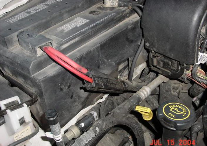
I put a separate single terminal under the relay cover (the one right in front of the battery) to use for attaching separate relay wires, and the EFI power supply wire. Also moved the alternator charge wire to it. Ended up with a stack of ring terminals on the single post but they stay clean and dry, unlike the other places that they were attached. If you decide to use relays for things like the headlights or marker lights like I did you end up with no convenient place to attach to the system. Plus, once I cleaned up the positive battery post it was easy to use one of those plastic post covers to keep it dry. If I was starting over, I'd probably get a box like Hussein's with a few extra terminals. And the reversed battery posts, of course, to bring it out from under the fender. Or mount the box on the relay cover and just run a short charge wire over to the battery post.
-