Zed Head
Free Member
-
Joined
-
Last visited
Everything posted by Zed Head
-
 You could check the switch for shorts to ground or shorts to other circuits. If it checks out then the very small amperage of the relays probably won't bother it. You can also check the downstream circuits for shorts also. Which relay kits did you get? Both the headlight circuits and the running lights can overheat.
 -
That Facebook link brings up a blank page. Doesn't even ask for a log-in. What's a "commerce/listing"? Shouldn't it be on Facebook Marketplace?

-
Here's another that shows the little pieces. Don't lose them.
-
Here's one that covers much more than the headlight switch. Pic 37 is about the starting point. About 2/3 down the page.
-
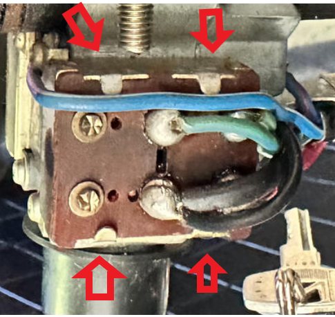
Carefully bend the four metal tabs back and the contact board will lift out of the case. Be very careful, there are small springs and things inside. You'll probably find pitting and maybe something melted. If you can get things cleaned up and use relays it should be fine, with the lower current. Be careful with the wires and solder joints. After many heat cycles they get brittle and often crack and break off. It's a pain resoldering them. Looks like somebody might have been in there already. There a threads about working on the combination switch I'll post one up if I find it.
-
@Terrapin Z might have a set.
-
Here's another. I thought it might be an investment flip but there seem to be other reasons. Kind of humorous. https://bringatrailer.com/listing/1970-datsun-240z-108/ https://bringatrailer.com/member/2shots/
-
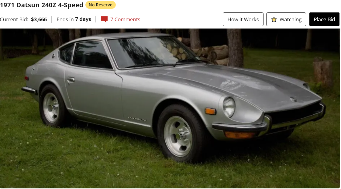
Very nice 1971 No Reserve. https://bringatrailer.com/listing/1971-datsun-240z-271/

-
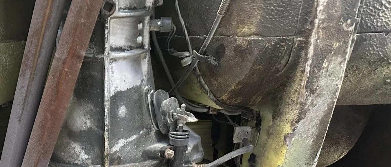
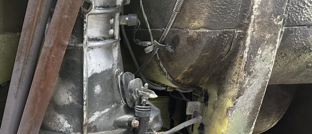
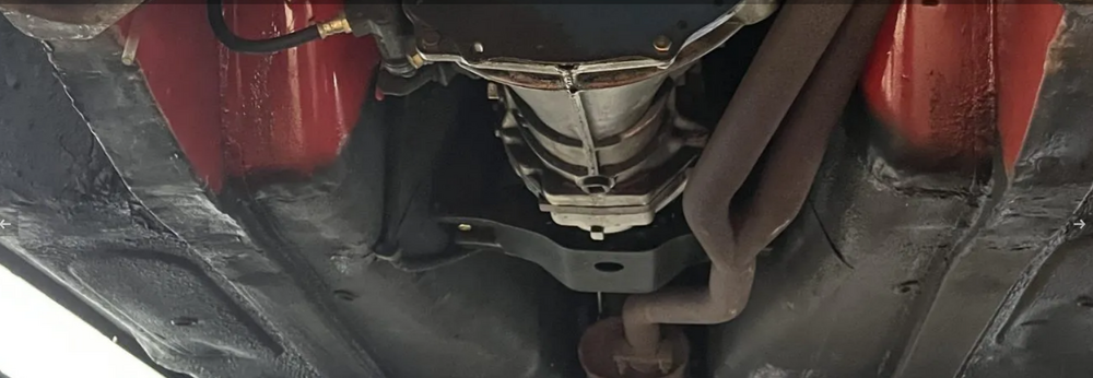
Overall, the whole thing was kind of odd. He said that he's been visiting the Guild showroom for years. Wouldn't give the name of the builder on the open forum but said he knew who it was and would supply it to serious bidders. But then later in the posts said he had a vague memory, like he wasn't sure, that the guy's name was Larry. But then said he had contacted the builder about the parts on the car, so he must have known him pretty well. Almost like the three of them were teaming up to sell the car. Very strange. I saw some odd stuff on the bottom of the car. It was painted black up to about the ends of the floor pans. The welds there look odd compared to other unmolested cars. The door jamb tag is a reproduction. There are two different firewall VIN stamp pictures in the listing. Edit again. I'm spending too much time on the internet. Anyway, I had wondered about this. Why stop painting there and why do the welds look so chunky. Here's a comparison. https://bringatrailer.com/listing/1972-datsun-240z-289/
-
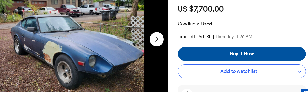
Here's something different. Only $7,700! https://www.ebay.com/itm/325776092449

-
Seems like he might have paid for the looks and now he's finding out what's underneath as he tries to move it on. Funny that he says he spent years trying to buy it but knows so little about it. Wonder where it will end up next.
-
That's a first. Should be an interesting project. The cam towers have a lot of mystery attached. Nissan says that if they're bad the whole head needs replacing. You probably have read that. Then, of course, there's the "tap the towers while spinning the cam" adjustment method if they're removed. Haven't seen towers from a different head tried. Seems like it should be possible, if the cam spins freely what could go wrong. Too bad they don't have "tower saver" journal inserts. Maybe you could make some.
-
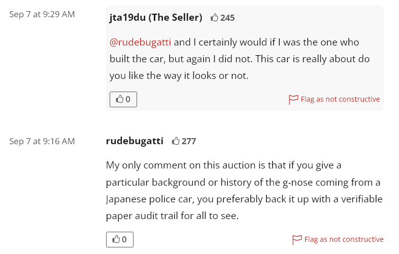
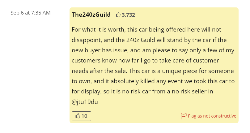
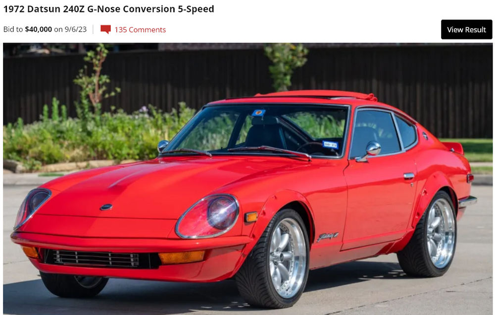
The comments continue on that red G Nose 72 even though the auction ended yesterday. Apparently it's meant to be a show car, as The Guild guy inferred earlier. I copied the image before it gets removed as "non-constructive". Kind of feel bad for picking on the guy's car but he doesn't want to let things fade. He's asking over $40,000 for it, so he can't expect no questions asked. What does $40,000 get you? What he should do at this point is put that paper trail together, documentation of it's provenance to remove the mystery, and put it back on the market in the right way. $40,000 is a risk unless you have money to burn. Drama!
-
You might turn the head upside down and fill the passage with oil to see if it's leaking from the cam journals like you mentioned earlier. Or some lighter fluid like kerosene/diesel/heating oil. That was a thought that seems on target. You could also just blow compressed air in and see what happens.
-
If you click Images here a bunch comes up. It's a hot topic! https://www.google.com/search?q=coolant+temperature+sensors+curves
-
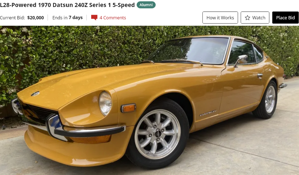
Is a plain old 1972 240Z with a G Nose (of questionable origin), a nice paint job, and an odd "sun roof" worth $40,000? I thought the guy did really well. The 72 alone was probably worth $25,000. That's a $15,000 premium for the three additions. Hard to figure where the additional value comes from beyond that. It's a nice-looking shell on an old 72 with a 5 speed, right? I wonder what his reserve was. The Z collector world is a strange place. https://bringatrailer.com/listing/1972-datsun-240z-287/
-
Might as well fill in some of the blanks on the saga of the 240Z"G" on BaT. Here's a Google that has a bunch of links about The240ZGuild and one interesting story that I pulled out. People on BaT are getting upset that the history of the car is being discussed. But they're not going to buy the car. https://www.google.com/search?q=the240zguild https://zclub.net/community/index.php?threads/franklin-mint-1970-datsun-240z.25773/page-5 The BaT link again. It's an interesting discussion. Reminds me of California Datsun. There's money to be made on those old Z cars! https://bringatrailer.com/listing/1972-datsun-240z-287/#comments-anchor
-
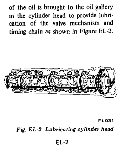
The oil jets (restrictors) are designed to maintain pressure to the lower end. It's a balance between top and bottom. If everything is to spec. it might be that the bottom end clearances are too loose and bleeding off the pressure. Maybe you're looking at the wrong parts. Maybe the low flow at the top is a sign of too much at the bottom. Could also be that you have a restriction from the jet to the spray bar. Through the head, in to the towers, and then to the bar. A new spray bar wouldn't fix that.
-
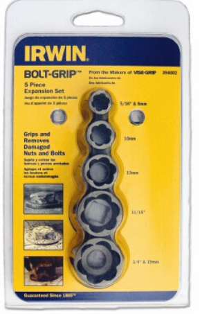
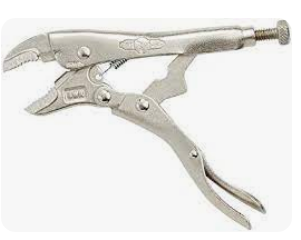
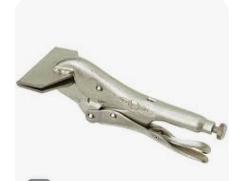
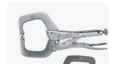
The Irwin extractor's I showed are completely external. But, to my point about finding a friend who knows cars - there are some methodical steps that should be taken to maximize the odds of getting it out. For example, you can file flats on the sides of the nub that the flats on the Vise-Grips can grab. It's more effective that relying on the teeth of the grips, which destroy as they bite. And there are ways to get a better view of the working area, like working through the tire well instead of from above. The right person with a welder could have it out in a few minutes probably Unfortunately most people learn those lessons the hard way after they've already destroyed the remnants of the stud/bolt/whatever. Seems like you're at a point where you can avoid major problems if you get the right plan in place. You left out the part about sawing off the sending unit and the fact that the nub turned a little bit. That's actually a good sign.
-
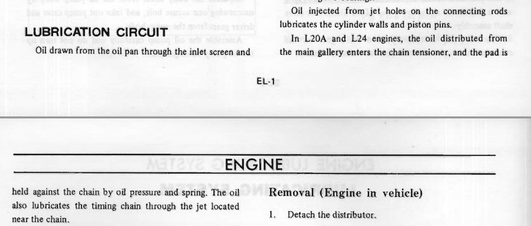
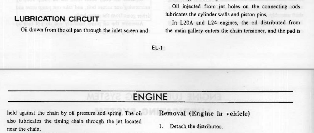
Did you mean timing chain? Nissan removed the description of the front oiler in the 1976 FSM. They mention chain lubrication but not the specific oil jet. Here's 72 - Here's 76 -
-
I got the impression from somewhere that the front one is not really necessary. It might even be discontinued in the later engines. Might have read it in the Rebuild book. You could pull them out, do some work on them, and replace them without introducing swarf in to the engine. Looks like they're still available. Could probably make your own also. 12 and 13 https://www.carpartsmanual.com/datsun/Z-1969-1978/engine-280z/cylinder-block https://www.nissanpartsdeal.com/parts/nissan-jet-oil-cyl~11047-e3000.html
-
One possibility that I haven't seen discussed is to find a coolant temperature sensor that has a shifted curve, shifted to the lean side compared to the Nissan curve. If you could start lean, you could use the 3 bar FPR, then you could use the "sensor tweak" to bring the curve up. I'd guess that a common thermistor material was used by many manufacturers. Who knows, maybe somebody started in a different spot on the resistance scale but the shape is the same. The Nissan curve has been derived on the forum by CO, from the FSM numbers and I think he did some tests. @Captain Obvious Maybe GM or Volvo or BMW has one with possibilities. Probably hard to find their curves on the internet but it might be fun to test a few.
-
Here is the inverse option to what SteveJ suggested. Goes over the part. Sometimes they work. https://www.napaonline.com/en/p/VG_394002
-
What kind are you using?

-
If you have a friend that's handy around cars you might ask them to take a look. It's a tapered thread, so, really, a pair of pliers or Vise-Grips should work. You might stick a mirror or a camera down there and see how big the hole is. Some might not need drilling.