Zed Head
Free Member
-
Joined
-
Last visited
Everything posted by Zed Head
-
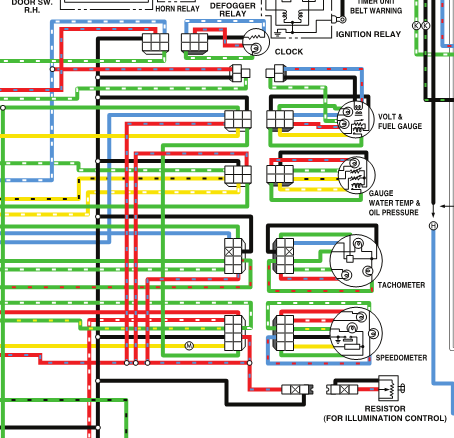
 The potentiometer would just provide the final path to ground. Each bulb's resistance stops a dead short from happening when the pot. is at zero resistance. So the theory that there's a short in one of your gauge bulb plugs or one of the other bulbs controlled by the pot. seems to fit. It would be a different kind of short, not to ground as usual, but across the intended load. The pot. just completes the circuit. It's odd though that you've had two potentiometers that are off-on instead of a gradual resistance. Hard to see how a short in the circuit before the pot. would cause that. Since you can remove the plug, a $3 Radio Shack potentiometer might show something. Maybe you got two bad potentiometers. You didn't mention year of car. I added a 1976 picture, but the early cars had some odd wiring schemes. Edit - may not change much, but the potentiometer may not actually go to zero resistance. The diagram shows a direct power feed to the pot. itself. So the final resistance in the circuit may be the pot. illumination light itself, if there is one. Or the diagram may be incorrect. Edit 2 - the electrical guys already knew this but the above (italics) is wrong thinking, That extra red circuit is just the ground for all of the other lights like the AC.heater controls and cigarette lighter. There are a lot of lights on that potentiometer. Any one of them could be the short.
-
The seller says sale fell through, so the $17,600 must have been over the reserve number. No new pictures though, still hiding the front end damage.
-
By manually you mean with a wrench on the damper bolt? I wouldn't trust those numbers, even on a freshly run engine. You'll get some leakage past the rings when things are moving that slowly. If you've adjusted lash on these engines you'll know the sound. But beyond that, 11 years of not running will almost certainly allow some rust in the cylinders and valve seating surfaces. Might be worthwhile to mount the transmission and starter and give it a good spinning with the plugs out, then re-test. I don't think that your results are very informative. Do you know anything about the engine? 200 psi+ is well over the pressure you would see on a stock engine. The 5 and 6 numbers are strange.
-
You could try new bulbs. Filaments wear and light output drops over time of usage. I saw a noticeable difference when I installed new stock headlights.
-
From the Portland Oregon area. Actually east toward Mt. Hood. Doesn't look bad, supposedly dry inside and it runs. Rims alone might be worth the price. A fairly cheap project car. 1978 280z Datsun
-
Find some old open diffs and take their shims. You might also try to cross-reference the parts to other brands and models. For example, truck diffs might be plentiful. Of course, luck will be required to get those numbers.
-
Things expand when they get warm. Gaps can open up. That's all. The current flowing through the wire and fuse caused the parts to heat up, the gap opened, the current stopped, the engine died. Then he would he sit beside the road and wait, the gap would close, the current could flow again, and he'd start the engine and drive on.
-
I would take a look at the relays involved. They're mechanical and do get stuck or sticky. Actually, I would just trace out the whole circuit that feeds the ignition system and the EFI system and examine each component and connection. I know someone that had a fuse in the trunk that would overheat while driving, opening the circuit at the connection points and killing everything, but leaving the fuse intact. After cooling, back to normal. It was a BMW though, so not directly applicable.
-
You can build a bump starter with a piece of wire and a single female connector of the same size as the terminal on the starter solenoid. The wire just needs to be long enough to reach from the solenoid to the battery positive post. Two feet is about right. OR, even more primitive - a screwdriver to bridge the gap between the end of the positive cable and the solenoid terminal.
-
If it's a manual transmission you can put it in to high gear and move the car by pushing on a tire to turn the engine. That will get you close. Then twist the distributor shaft mechanical advance mechanism to get on the lobe.
-
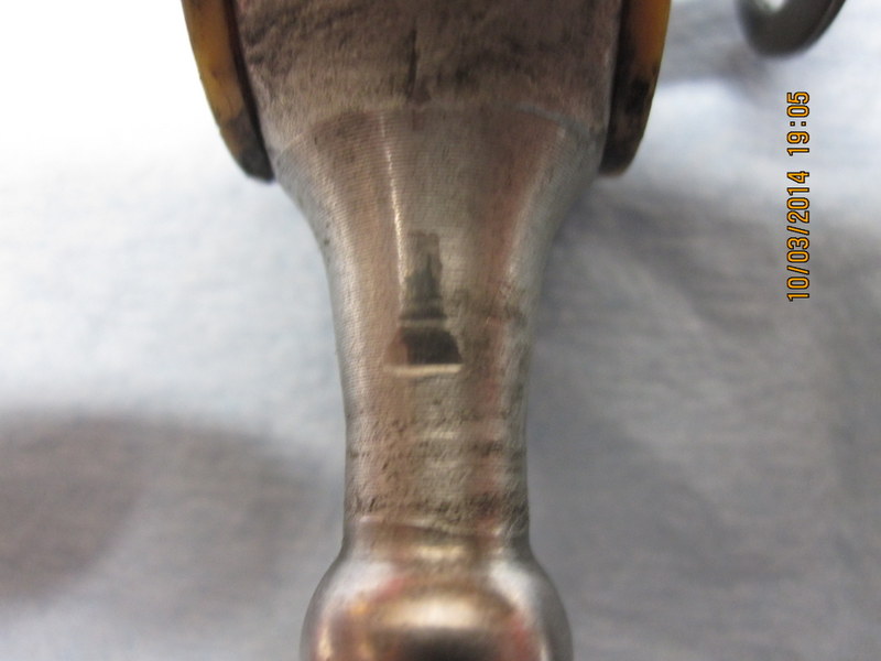
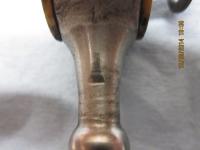
I'm guessing that there's a stud under that rubber. Maybe someone missed a step during manufacturing and didn't clean up the leakage. Or somebody forgot to put the bolt in but poured the rubber anyway. The two holes are probably for the big ugly vibration damper that Nissan added to later Z's.
-
Timing could be a factor but it would most likely be a consistent problem. Does the no-start happen randomly, whether the engine is cold or hot, or is it only when hot?
-
Oops, I missed the fact that Test 6 asks the same thing. What they want you to do is to ground the center wire of the coil, the big one that's the same size as a plug wire, to the block so that the current from the coil has somewhere to go. So that you can crank the engine over without the engine starting. So pop the wire out of the distributor cap. leave it connected to the coil, and place or clamp the metal end against a solid piece of metal on the engine block. Just make sure that it's solidly placed, if it gets loose it can spark to things that shouldn't get spark. And if it's too far away to spark, the electrical pulse can do other damage if it has no way to discharge. As I understand things. The spark from that wire will be a big one.
-
The test connections are at the connector/plug ("receptacle" = receiver) so your second tests were correct, and results look good. I would do Test #6, since that measures voltage during starting. Your starter could be drawing too many volts or your battery could be weak. I would also do something similar Test #9, since the module grounds through the distributor body, except Iwould just measure resistance to ground. The ground is the other important part, that allows current flow. You can have correct voltage but low current and have problems. Measure resistance from the distributor body to the engine block. I don't know why they test voltage drop with the coil discharging. It seems like a good way to make a mistake and damage the module. Check the ground first.
-
One of the handy features of the Z's and ZX's is that the hood opens forward. Get some 1 - 2' test leads with alligator clips on each end and set the meter up where you can see it from inside the car.
-
Check for spark first. Make sure it's a good solid blue spark, not a weak thin yellowish spark. If you have no spark... A bad ignition module or dirty connections at the ignition module are a possibility. They're in a dirty. dusty spot and the rubber seals and wire insulation tend to get baked and cracked. The module and coil need a good voltage supply to create a good spark. When the engine is cranking voltage drops. A few more lost volts due to dirty connections could be enough to weaken the spark during starting. Finally, when did you last give it a tune-up? Worn, dirty spark-plugs can cause problems.
-
Read three more pages in the Owner's Manual. Do not push.
-
Barns. They must be found in a barn.
-
For the record. Things got real weird in the last half hour.


-
There's always some little thing that makes you think twice on these high asking price cars. Who lists the brand of their fuel filter? It's listed in the magazine article also. They probably mean fuel pressure regulator, but it's a sign that somebody has either just bought a bunch of brand names or the seller doesn't really know what they have, One of those odd things. It's not even an auction, just a set price Buy It Now. "Fuel safe trunk mounted fuel cell (16 gallon) Aeromotive fuel filter Walbro 255 fuel pump(mounted in trunk)" "To move fuel from the trunk to the engine bay, a Bosch 044 inline pump with an Aeromotive filter ensures steady delivery of 91 octane to the quartet of RC Engineering 750cc/min injectors. With these issues addressed, JDM Concepts could finally tune the engine."
-
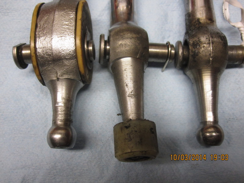
I have three different levers, not including the one n my 76. A straight lever with the spring-loaded pivot, from an 83 ZX 5 speed I believe, a straight lever with no spring-loaded pivot, from an 80 ZX 5 speed, and a bent lever, from a 78 5 speed. They all have the notch marks, but the Zx levers both have long scrapes in addition. A person could probably spend some time fine tuning their shift mechanism. I'm surprised at the variations. The middle lever is the 280Z lever.
-
No, I just wasn't clear on what the real problem was. That's why I said it was weird. As I noted, the real issue isn't the throw, it's how deep the longer arm (of the "shorter-stroke" shifter) sits in the hole. So grinding the top of the hole away is the correct solution. Edit - actually, I think that it's just too wide at the base of the shaft of the actuating portion. Because, assuming the same diameters up to the pivot point, the one with the longer actuating arm should end up farther away from the edge of the hole. That is the heart of all of my confusion. Edit again - actually it won't end up farther away at that point. It's an interesting exercise. Since the bottom of the actuator is moving the top of the striking rod cylinder closer to the top of the actuator, it makes sense that it would bind in that spot, since the bottom of the actuator moves the whole cylinder farther before the top of the actuator can get out of the way. Probably clear to many, I just didn't get it. It may be why, though the later ZX shifters have a spring loaded moveable pivot point. When you press down on a ZX lever you get a long actuator, then if you release the downward force the spring pushes the whole shift lever back up. That would give the benefits of a short-stroke (long actuator) lever without the binding problem described here. Sorry for cluttering up the thread. I did figure out some new things though. I might try a ZX shifter in my Z to see what happens. We're all in agreement on short-stroke shifters, and how they work.
-
What I would really like to know though, is where the shifter with the longer actuator below the pivot point came from. All of the ones I've seen have about the same length. I'd like to have one that gives a shorter lever throw. Another edit - I'm going to guess that the rod on the left is a 240Z rod, and the one on the right is 280Z. I already have several of those. So no luck for me.
-
My mistake in not being clear. I should have stopped with - what lever are you using?
-
My apologies. I mixed up my terminologies, using throw for the actuating portion below the pivot, and for the lever itself. What I said wasn't backward in whole, it was internally inconsistent.