Everything posted by Zed Head
-
 It shouldn't be a problem. The screw holes are still intact and will hold the pieces in place. Like Darrel said, they don't need to be very tight. Once the screws have pressed the injector seal down in to the hole, and squeezed the insulator and metal top piece together and down to the manifold (no gaps), there's little benefit to being tighter.
 -
"china junk" got me. You ask a lot, then offend. It's just a bad combination.
-
1.2" - 1970-1973 Nissan 240Z STAGG Shocks/Struts and VOGTLAND Lowering Springs Kit (1.2" Drop) The link probably looks familiar. Catch up on how business and manufacturing works, if you can. Add a little bit of the world in general. Expand your mind, the narrow view will really limit you in the long run.
-
I edited my other post with a few more thoughts... In case you missed them.
-
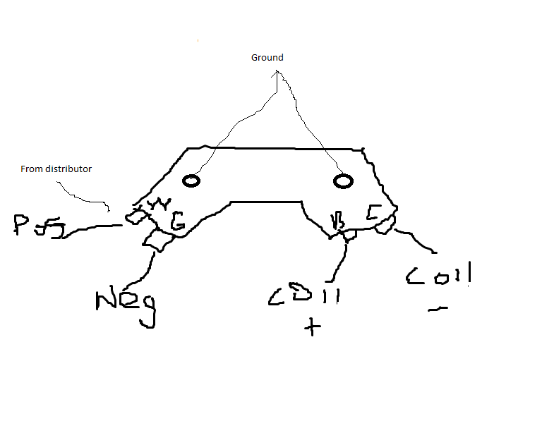
The old 75 distributor will work great with the GM module. Here's a diagram that I spent a few days putting together. Connect the red wire to W, the green wire to G, and B and C as shown. Make sure that the mounting grommets are electrically grounded. Missed the internal part. There's not enough room inside for the GM module. But, if I was going to do another one I might mount it in the cabin where the old ignition module was. The red and green wires from the distributor run all the way there, along with the old coil positive and negative wires. You might need to fabricate a mounting plate. It would take some time with the wiring diagram. For a test though, it might be simpler to just run jumpers from your ZX distributor. You can take the ZX module off of the side and the two wires you need will be right there. Choices.

-
That's what I meant when I said that you might have to rotate the distributor. Mark the position of the distributor base so that you can get back to it when you're done, loosen the hold-down screw (the one you would loosen for timing), and rotate the whole distributor body. This will move the module in relation to the magnet. If you can see where a magnet is though, you could bump the engine around until it's close, then grab the rotor and twist. you should have about 10 degrees of rotation of the rotor from the mechanical advance. Not much, that's why it's easier to rotate the distributor body. You could also put the car in gear and roll it back and forth but that wouldn't be very quick and it would be hard to keep an eye on the meter.
-
Considering the time, effort and aggravation you've spent so far, maybe a trial of a GM HEI module would be worthwhile. $25 and some wiring versus $75 for a new ZX module. High RPM weirdness is a typical failing module sign. It could also be the distributor though. Have you checked the gap between the iron rotor and the pickup points? Described n the 79 FSM. The rotor needs to be perfectly centered. The pickup coil magnet tends to break on the ZX distributors also. I've seen it but don't know if they still work when broken. If you're not in to wiring or electronics, maybe $100 for a spare distributor would be worth the money. Or, maybe you could borrow a spare from somebody.
-
Post #4 in this thread links to a vendor. They sell a package so the assumption would be that Stagg knows. Not really confirmed though. New S30 Shock and Spring Option - Vendor's Forum - HybridZ
-
What engine/car are you working with?
-
I found the instructions linked below on the Summit Racing site. They don't exist on the Pertronix site. Good luck. The first test should tell you if the module is working. You might have rotate whole distributor to get the sleeve to move enough in front of the module. Pertronix doesn't seem to be supporting their older products. You have to wonder about quality control. http://www.summitracing.com/parts/pnx-1761/media/instructions
-
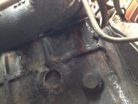
I had a similar leak, bit on the other side. After I removed the engine (put another in), I removed the head and all of the other sealing areas were fine. It only leaked from a coolant passage outward. Rotated your picture for you.
-
I missed jmortensen's post somehow. I think that by 76 Nissan was doing the greased then sealed with a screw joints from the factory. Don't try to take the joints apart whatever you do. They were assembled with precision ground locking clips to set the clearance. They're actually much higher quality parts than what you can get from a parts store. Nissan replacements cost about $80 and come with a set of varied thickness clips so that you can set perfect tolerance.
-
Did you grind off the peened area of the nut? Fuel pump? A least you're not trying to hold to the "rational changes to fit the tires" model anymore. Have fun.
-
You really should measure voltage, before going too far. No power, no spark. And the voltage measured will depend more on whether or not the ignition module is passing current, than the ballast resistor. There is a troubleshooting guide out there about Pertronix modules. It's not very good though. There's actually better troubleshooting info in the installation instructions. You'll need the model number of your module. Troubleshooting Tips (Ignitor) PerTronix Instruction Sheets
-
The Bar's material stays in gooey blob form. It just travels around, occasionally getting sucked in to a leak area, hopefully sealing it. Leak solutions are messy looking, just like the leaks. Most of them also contain lubricants for the water pump seals also. Not meant to be observed, just sealed in and left to work.
-
Yes, the screws are removed, replaced with Zerk fttings, grease applied, then screws re-inserted. Take some time to find a socket that will fit the Zerk fittings, you might have to grind one down to fit in the tight area. Even the screws will be difficult to remove, make sure you use a good-fitting screwdriver and don't strip the slot. They can be very tight. You'll probably use the same Zerk fitting so just buying a range of small, fine-thread Zerk fittings will probably get you there. Sometimes you'll actually find a short one that is left in place. Also, you might have to grind the sides of your grease gun tip to get it to fit in the tiny space of the u-joint. Or find a thin wall tip. Or, just take the screw out and use a rubber tipped nozzle to insert the grease. Then you won't need a Zerk fitting.
-
Are these solid state regulators or the old mechanical type? Maybe your alternator is frying the solid state regulators with voltage spikes from bad internals. Is your alternator case grounded well?
-
Now you're changing your story. Or you didn't read the link you posted, person. From the Wiki link (bold italics mine) - "It occurs when the liquid fuel changes state from liquid to gas while still in the fuel delivery system. This disrupts the operation of the fuel pump, causing loss of feed pressure to the carburetor or fuel injection system," On a progressive (as in making progress) note, I'm 80% of the way to trying out some 1990 era injectors, of the four hole, high impedance type. Just to see if any design improvements happened along the way. I notice that the high impedance injector pop open with less voltage, even though resistance is higher. More windings, I think (another area I don't know well though, like transistors). If it's a mechanical binding problem, or solenoid resistance increasing due to heat, maybe more opening force will help. Hopes aren't high but I think it's worth a shot. I'm bypassing the resistor pack so there's a lot of new happening.
-
There's very little rational reason to own these old cars, no matter how you look at it. I just accept the fact that I'm spending time and money on something I don't need, because I enjoy it. Here's another option for adjustable coilovers. Don't know the timing, sometimes these things never end up actually happening. ***** BC Racing coilovers for S30 ( Whats the interest? ) ***** - Brakes, Wheels, Suspension and Chassis - HybridZ
-
I get involved in some threads just for the logic challenge. Like solving a puzzle. You did ask for advice, and I tend to be very literal. The rationale for the GC kit, supposedly, is to get the 225 width tires under the fenders. That's a lot of time and money spent just to fit a wide tire. You might be able to have the fender lips rolled for a few dollars, get some spacers or a different offset rim, and keep everything stock. If that was a possibility, would you do it, or would there be some other reason to get the GC kit? I'm betting that you'll find another reason to get the GC kit. Matching expenditures on various car areas makes no sense at all. I spent a lot on the engine so I must spend a lot on the suspension? Not logical. If you're just having fun modifying the car, then you'll get a lot more love and advice over on Hybridz. There's nothing wrong with doing it, just come out and say that's what you want to do. I'll bow out now. It's your money and your car.
-
Do you have AC? Pretty common for the bearing in the tensioning idler pulley to go bad. It's easily replaced, and the bearing is a common one, readily available. You can run the engine for a short while with no belts. The battery will power the EFI, and it won't overheat for the few seconds necessary to listen for noises, with no coolant pushed from the water pump.
-
Just want to make sure you didn't overlook this comment. You seem to be doing it for the bling, not to make a better car. Not to be negative, but you did start the thread seeking opinions.
-
It looks like you really want to go with the adjustable coilovers and camber. But if you decide to wait a while, or realize that your budget isn't quite ready, here's another, less expensive option - New S30 Shock and Spring Option - Vendor's Forum - HybridZ
-
You are right. I should have done this three or four years ago. Although it has been interesting battling the old XP to keep things working. Kind of like working on an old fuel injection system.
-
It doesn't look there's any benefit as far as choice of shock. All you'll be getting is the adjustable height from a lower starting point and adjustable camber. From the GC site - "This kit fits 70-74 Datsun 240 and 260 Z WELD with stock, Sachs, Boge, Tokico Premium Performance, Tokico Illumina, Koni, or KYB shocks (please specify shock type before ordering)." Those are all typical Z car shocks, from low budget Rockauto type to the type that aren't available anymore (Tokico). And you have to supply your own. So you'll still be looking for shocks, just shorter ones, when you get the parts back. It's a problem.